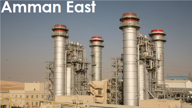
Reliable electric supply in the Kingdom of Saudi Arabia depends to a large degree on the proper operation of gas turbines, which dominate the country’s generation infrastructure. At the end of 2018, Saudi Electric Co (SEC), the leading producer of electricity with a nominal 70% market share, had 53,500 MW of capacity installed at its 40 powerplants. Simple-cycle gas turbines comprised about one-third of that total, combined cycles a quarter, and oil- and gas-fired steam turbines most of the remainder.
Worth noting is that Saudi Arabia is the world’s largest producer of desalinated water, relying on 17 facilities to provide that product. Several desal facilities have been sited together with power stations.
Many types of gas turbines are installed in Saudi Arabia for electricity production and mechanical-drive applications. They include the GT11, 501D5, 501D5A, V84.2, M501F, Frame 5, and 6B; most are scattered among the various IPPs and industrial self-generators. By contrast, SEC relies heavily on GE Frame 7s and has more than 150 EAs and FAs in its fleet.
SEC plant personnel often participate in 7F Users Group meetings in the US, but it’s impractical financially for more than a few of the company’s many engineers to attend. A solution was to hold a Combined Cycle Conference (Apr 3, 2019) and a Power Generation Technical Workshop (Dec 11, 2019) in Saudi Arabia.
The first meeting, sponsored by SEC, was hosted by the Ali A Tamimi Co and coordinated by Keck Group International LLC (Fig 1). Tamimi is a respected provider of engineering and onsite O&M services—including turnkey upgrade projects—to SEC and others in the power, petrochemical, and oil and gas industries. KGI, headed by two former GE executives—Richard Keck and Bob Johnston—provides consulting services in support of combined-cycle operations and performance improvements.
![]()
The second conference was sponsored by Saudi Aramco, a/k/a Saudi Arabian Oil Co, at its facilities in Dhahran (Fig 2). Saudi Aramco, which owns 7% of SEC, is both the utility’s main fuel supplier and an important customer.
![]()
Combined-cycle conference
Adel Al Shuraim, CEO, Tamimi Energy, opened the Combined Cycle Conference. His welcome was followed by that of Khalid Al Tuaimi, EVP, SEC Operations. The morning’s technical presentations followed, beginning with recommendations for improving combined-cycle performance by CoreTech Industrial Corp’s Joel Holt, engineering manager and Bruce Martindale, consulting engineer.
Holt (Fig 3) and Martindale did double duty, following up their opening presentation with a primer on how to reduce plant startup time. Johnston was next with a review of uprates for non-capital parts—with no changes to existing gas-turbine capital parts.
![]()
HRSG improvements were addressed by CMI Energy’s technical manager, Raphael Stevens and VP Habib Grini.
Presentations on steam-turbine upgrades and training programs for gas-turbine, steam-turbine, and generators, were developed by MD&A’s Eamonn Rogers and Dave Hagenbuch.
Exhaust-system upgrades and repairs, by Innova Braden Europe’s Ed Chan and Moustafa Al-Shami, closed out the morning program.
The afternoon was reserved for Q&A and open discussion.
The presentations focused on specific issues that each vendor had addressed at combined-cycle plants and showed how that experience could benefit generating facilities in Saudi Arabia. The vendors participating in the conference had agreed to work collaboratively to provide owner/operators of the kingdom’s 15 operating combined cycles complete solutions. Representatives from all those powerplants were among the 100 or so attendees.
Saudi Arabia’s combined-cycle infrastructure includes the following, based on CCJ’s research:
-
- Ten 7EA-powered 4 × 1 plants designed for crude oil only. Gas turbines, rated 56 MW each, installed from 2010 to 2012; 130-MW GE steam turbine/generators added to each block between 2014 and 2016 along along with unfired NEM HRSGs.
- A 7001FA-powered 3 × 1 designed for gas only installed in 2012, equipped with Hyundai HRSGs and a GE D11 steamer.
- A 7000FA-powered 4 × 1 designed for gas only installed in 2013, equipped with Hyundai HRSGs and a GE D-11 steamer.
- Two 7F.05-powered 4 × 1 facilities designed for gas with oil backup. Gas turbines, rated 172 MW each, installed in 2014-2015; Alstom HRSGs and 341-MW steam turbine/generators added to each block in 2017.
- Four 7F.05-powered 3 × 1 facilities designed for gas only are scheduled for 2021 operation. Gas turbines, rated 215 MW each, will be integrated with Alstom HRSGs and 342-MW Alstom steam turbine/generators.
Featured Solutions Provider
Holt and Martindale breezed through a review of the principal systems and components in a combined-cycle plant, explaining the functions of each in relatively few words. Then they summarized plant startup (hot, warm, cold) and shutdown procedures, identifying issues sometimes experienced with each step and how to avoid them.
Technical warmup complete, the speakers were ready to tackle one of the meeting’s primary objectives: Encourage attendees to pursue procedural and equipment changes to enable faster starts of their combined cycles without compromising reliability and service life.
The significant penetration of renewables into the power generation market has caused many combined cycles to switch from baseload operation to cycling duty—including the ability to start quickly when non-fuel resources suddenly disappear.
The speakers noted that combined cycles installed in the last five years or so typically were designed and equipped for the new demanding service. But some older plants are not able to accomplish warm starts in less than four hours, which makes profitable dispatch difficult, if not impossible, in today’s competitive power markets. However, new procedures, software, and some equipment upgrades, the group was told, could drive down plant warm restart times to 90 minutes with a generally acceptable investment.
Performance improvement was another topic of major interest given older combined cycles have suffered efficiency reductions over the years. To fully assess areas that should be addressed to improve thermal performance, the speakers recommended doing a current heat balance and comparing it to the original. The main areas requiring improvement will stand out, it was said.
Focused uprates within the capability of existing equipment are a proven path to performance improvement. Keep in mind that most older gas turbines receive upgraded parts when they purchase replacements or spares because OEMs are continually improving the capability of their offerings.
But manufacturers rarely assess the overall capability of the GT when only selling parts. Owner/operators, sometimes assisted by an independent consultant, frequently find a thorough review can guide the selection of parts capable of increasing GT output by as much as 3%, possibly more. This, plus the accompanying increase in exhaust energy boosts overall combined-cycle power and efficiency.
A comprehensive audit of the physical plant, and of the procedures that guide operations, often point to affordable improvements with big returns. The HRSG can be an efficiency hog when wear and tear allows flue-gas bypass of heat-transfer surfaces and catalyst by way of failed baffles and seals, and when gas- and/or water-side deposits retard heat transfer. Steam-turbine upgrades and repair/replacement of key exhaust-system components—ductwork, dampers, etc—can provide significant benefits as well.
Bob Johnston’s “Non-Capital Parts Uprate Program” was an ideal sequel to Holt and Martindale’s presentations, which focused on equipment. Johnston’s “program” focused on applying non-hardware related controls changes to match the capability of hot-gas-path (HGP) parts, thereby increasing gas-turbine output and efficiency. The speaker told the group that all the parts of his “program,” which have been applied successfully to scores of GE engines, also can be used to improve the performance of machines made by other OEMs.
He should know. Johnston, a four-decades GE veteran, retired in 2008 as manager of the company’s Gas Turbine Services Engineering Group, which supplied upgrade/uprate packages for a fleet of more than 7000 frame engines. Industry veterans likely have seen his name on documents in their files.
Johnston began with a review of items that could result from a non-capital-parts uprate study—including the following:
-
- Higher firing temperature possible with improved HGP parts.
- Change in the angle setting for inlet guide vanes (IGV).
- Increase in power at higher ambient temperatures by changing the isotherm setting.
- Exhaust-thermocouple corrections.
- Degradation correction to the control curve.
- Use of a tilted control curve to improve hot-day performance.
The speaker put up on the screen a valuable table of key data for all Frame 7 models from the introduction of the PG7651A in 1970 to the PG7241FA in 1999. It includes rated output, firing temperature, air flow, heat rate, and exhaust temperature—information needed for comparison purposes in performance studies.
Johnston’s “carrot” was that for any “older” unit, it is likely that sufficient parts have been upgraded through normal supersedure procedures such that they would enable your gas turbine to produce more power. A thorough HGP review can confirm this. He added that most Frame 7 spare parts introduced after your engine was built are directly interchangeable with those in your machine. To illustrate: The later-vintage spare parts for the MS7001B/C/E/EA machines are directly interchangeable with all prior vintages of MS7001 units.
Attendee interest was piqued when Johnston said that degradation correction, along with use of the tilted control curve, had increased the output of some units operating in high-ambient-temperature environments by as much as 1.6%. Only controls changes were required, same hardware. For an MS7001EA this translates to about 1.2 MW of additional power.
The driver for using a tilted control curve is simply that most owner/operators value output on hot days more so than on cold days. Recall that standard GE control curves maintain a constant firing temperature at all ambient temperatures. Tilted control curves overfire on hot days by 16 deg F and under-fire by 25 deg F on cold days. Extensive analysis by the OEM in the mid-1990s was said to confirm that this approach had no net impact on parts life or maintenance intervals. Hundreds of successful applications were reported.
Non-recoverable performance degradation attributed to increased clearances, blade finish, and casing distortion, among other impacts, reduces output. Plus, it also adversely affects the compressor discharge pressure/turbine exhaust temperature relationship, resulting in under-firing of the unit.
The speaker said that extensive performance testing can be done to quantify the degree of under-firing, but that a 5-deg-F reduction in exhaust temperature and a 9-deg-F drop in firing temperature are typical. The simple approach, he said, was to apply an exhaust temperature correction to the control curve and regain the power lost (about 0.8% for a mid-1990s vintage 7EA).
HRSG improvements. The CMI presentation included case histories on HRSG modifications to match a gas-turbine upgrade, dry-ice blasting for tube cleaning, and retubing—topics typically covered in depth at meetings such as the HRSG Forum with Bob Anderson the European HRSG Forum, and the Australasian Boiler/HRSG Users Group (ABHUG).
HRSG mods to match a GT upgrade described work done at the UK’s King’s Lynn power station (COD 1997) in 2017-2018. The ambitious project included replacing the gas turbine, refurbishment of the HP and LP sections of the steam turbine, and its generator, and addition of a street to the air-cooled condenser.
Goal was to make the plant more flexible (300 or more starts annually), enabling its profitable operation in an increasingly competitive market. This required maximum use of existing infrastructure, improved output and efficiency, high reliability and availability, etc.
CMI’s effort focused on recovering heat from flue gas at higher temperature than could be handled by the 1990s HRSG. Redesign/replacement of the HP superheater and reheater was required. The presentation essentially was a collection of photographs “narrated” by the speakers to explain how the old pressure parts were removed and the new pressure parts installed—a confidence builder for those who may have thought such a retrofit project might not have been possible.
Case studies for energy savings—including tube cleaning and retubing of damaged heat-transfer surface—closed out the CMI segment of the program. Most of the material presented can be found in CCJ’s archives. Access by typing your request into the search function box at www.ccj-online.com.
MD&A’s program included a presentation on D11 HP/IP replacement, which might also have been of interest to many users in the US given the large number of D11 steamers in this country. Dave Hagenbuch focused on D11 issues reported by owner/operators and the features and benefits of MD&A’s solution—and that of parent company Mitsubishi Hitachi Power Systems.
Dished diaphragm repair options, “hot swap” and spare sub-assembly offerings for stop valves and control/intercept valves, and packing rings and seals also were covered in the steam-turbine segment of the agenda.
Training wrapped up the MD&A effort. Seminars offered on steam-turbine fundamentals, alignment, advanced repairs, and performance evaluation and improvement were described in addition to workshops on gas-turbine fundamentals and the Mark VI control system.
Innova Braden Europe presented its air-inlet and exhaust-system retrofit solutions for 7EA and 7FA gas turbines as the morning drew to a close. The speakers began with exhaust systems, covering typical problem areas in older-style plenums—such as hot flanges and outer skin, overheated turbine and load compartments, liner damage, etc. Solutions discussed were well illustrated to facilitate the transfer of knowledge. Much of this material has been covered in CCJ over the years and is readily available with a couple of mouse clicks. Just access www.ccj-online.com and use the keyword search box on the home page.
Bypass diverter dampers were the next topic. Once again, photos illustrated the problems encountered and the solutions available. Cracks on the diverter-damper frame, blade cover, and toggle arms all were discussed, as was damage at the seal-air frame of the diverter-damper blade and wear and tear at the connection to the diverter-damper blade hinge. This material does not get much air time at user-group meetings in the US because regulations here typically do not support the use of diverter dampers.
Diagnostic tools, such as acoustic cameras and drones, and project case histories from major plants worldwide completed the presentation.
Technical workshop
The Power Generation Technical Workshop hosted more than a hundred participants from Saudi Aramco’s engineering office and facilities. The agenda was similar—some presentations basically the same—to that of the earlier Combined Cycle Conference. Holt presented again on combined-cycle efficiency improvements and faster starts, Johnston on uprates of non-capital parts, and Stevens and Grini on HRSG improvements. MD&A covered its training offerings again and replaced some of the SEC steamer presentations with ones on gas-turbine rotor life extension and HGP repairs.
Several topics were in addition to those addressed at the SEC meetings, the prepared presentations running until mid afternoon when a panel was convened to address topics of interest not covered earlier in the day. Presentations added included these:
-
- Upgrades for air-cooled condensers, Frederic Anthone, manager of aftermarket support, SPG.
- GT inlet chilling systems, Tom Tillman, principal engineer, Turbine Air Systems Inc and Bob Johnston.
- Fuel additives for NOx emissions reduction, Mutasim Al Khayri, technical development manager, Clariant Al Tamimi and Bob Johnston.
- Regenerative-cycle conversions for all types and models of gas turbines, Ty Moore, VP operations, PalCon.
MD&A’s Hesham Awwad opened his company’s session with a presentation on GT rotor lifetime assessment (RLA). He noted that MD&A does not refer to this activity as an “end of life” evaluation, urging attendees not to “pull the plug” too quickly because an RLA can help owner/operators decide on the best options for ageing assets. He stressed that MD&A’s goal is to help users achieve their planned operating strategies for remaining life through validation, repair/coatings, and/or replacement of limiting components.
Awwad explained his company’s inspection process flow path, inspection scope and equipment, and testing and analytical tools used to develop a rotor-health assessment for planning refurbishment activities, or replacement through MD&A’s rotor exchange program. 7FA compressor upgrades, DLN2.6 combustion parts/repairs, and 7EA/7FA compressor and turbine replacement disks were included in this portion of the program.
Greg Alexander then moved to the podium to discuss new-parts manufacturing and component repairs. Repairs are performed on 6B, 6FA, 7EA, 7FA, 9E, 9FA, V94.3, and V84.3 buckets, nozzles, shroud blocks, and fuel nozzles. Company offers new HGP parts for 7EA, 7FA.03, and V94.3 machines, the group was told.
Inspection and repair of 7FA.03 and 9FA combustion and turbine parts is a focus of MD&A’s aftermarket business with a goal of reducing scrap.
SPG’s Anthone began with the requisite company history and product portfolios for both wet and dry cooling systems, moving quickly through that boiler plate to focus on the inspections, technical advice, maintenance services, and spare parts available to improve performance as operating conditions change. To learn more about air-cooled condensers, access www.acc-usersgroup.org where you will find presentations on a wide range of chemistry and O&M topics archived from the time the ACC Users Group was founded 12 years ago.
It’s no secret, turbine inlet cooling increases the power gas turbines can produce on hot days. Tillman’s presentation focused on water-cooled chiller systems with heat rejection via an evaporative cooling tower and these refrigerant options: R-1233zd (HFO) and R-134a. For plants located on the coast, seawater heat exchangers can replace the standard cooling towers. Typical filter-house modification kits were covered as well.
Users wanting background information on alternative inlet cooling technologies should visit www.turbineinletcooling.org and CCJ’s editorial archives at www.ccj-online.com.
Fuel additives for emissions control is an important topic for a Saudi audience given the large number of gas turbines burning crude oil. In these units, the speakers said, additive is injected upstream of the liquid-fuel stop valve. Focus of the presentation was experience with FuelSpec R114-05 (0.05% Mg/0.4% Fe by weight) in reducing carbon soot emissions.
Smoke and particulate measurements taken by an independent Saudi-based certified test lab, and performance data captured and analyzed by Saudi Aramco and US-based Efficient Fuel Solutions, revealed a reduction in smoke and particulate emissions of 30% when using R114-05, compared to operation on untreated crude oil. The additive injection rate was 1 liter per 130-million Btu. Test was conducted over two days.
Film-forming substances (FFS), intended primarily for the protection of metal surfaces, are not new. The earliest patent (known to the editors) for one such substance, octadecylamine (ODA), was issued in 1954, with first powerplant applications in the former Soviet Union and East Germany. Earlier still, FFS were used to protect shipments of military equipment during WWII.
What is more recent is focused research and trial into applications for combined-cycle plants. Hoped-for benefits include corrosion protection in heat-recovery steam generators (HRSGs), condensers, and the phase transition zone (PTZ) of steam turbines. Other benefits could be better pH control, and less chance of both single- and two-phase flow-accelerated corrosion (FAC).
But also new is an increasing risk of system and equipment damage caused by misapplication, misinformation, and failure to accurately prepare and monitor—in other words, jumping in too quickly.
Although the expected results sound great, potential damage—the industry is learning—can be great as well.
Is the use of FFS worth considering? Absolutely, especially given more cycling, low-load operation, and periods offline. Is this worth implementing, within an already complex water-chemistry program? It could be, depending on the system and equipment, and if you’re both knowledgeable and careful.
Neutralizing, filming amines. About three years ago, the CCJ-Online Team posted the following session review notes for the Combined Cycle Users Group, perhaps the only organization that covers water chemistry for the entire combined-cycle plant:
“The jury is still out on the use of amines,” but “addition of an amine with a low volatility at the pressure of concern may provide benefit: It will hang along the tube wall to protect against loss of oxygen and ammonia from that space. Absent amine, oxygen and ammonia can migrate into the bulk water, leaving the tube-wall area unprotected. Amine volatilizes later, but after protecting the tube wall.
“Bear in mind that amine blends are known to increase cation conductivity and possibly mask more corrosive anions. Their use is influenced by the severity of two-phase FAC and turbine corrosion. Monitoring of iron transport is highly recommended before introducing amine blends.”
Then CCJ ONsite published a detailed primer on this fast-approaching frontier, by EPRI’s Steve Shulder and Mike Caravaggio, entitled “Protect equipment against corrosion with neutralizing amines, filming products.” This detailed review covered the latest EPRI research into amines and filming products, monitoring of these substances in action, corrosion control in the steam-turbine PTZ, the need for new tools to quantify corrosion improvement, and a glance at ongoing research.
Since that time, the subject has been included, in some form, at all user-group meetings for combined-cycle systems and components—including turbines, HRSGs, and air-cooled condensers. Something has been happening.
A case study was noted in the inaugural (2017) HRSG Forum with Bob Anderson concluding with the importance (for all aspects of plant water chemistry) of “understanding the damage mechanisms and chemistry control options, performance monitoring, and the critical importance of acting on the measured results.” Measurement, it has been determined, is a difficult part of the overall equation.
IAPWS. The spearheading organization for both FFS research and implementation is the International Association for the Properties of Water and Steam. A key participant is Dr Barry Dooley, senior associate, Structural Integrity Associates Inc, and the executive secretary of IAPWS.
CCJ has been following Dooley (and others) on this for quite some time.
Amines, products, substances. The First International Conference on Film-Forming Amines and Products was held in Lucerne, Switzerland, in 2017. Before the second conference in 2018, organizers had issued a formal and much-needed change in nomenclature.
The term film-forming substances was introduced by IAPWS last year. Feedback from the first two conferences had indicated confusion about the various terminologies used within this relatively new field of chemistry, or what Dooley calls “a narrow topic in cycle chemistry control of powerplants.”
In response, IAPWS introduced the more general term film-forming substances. Two subsets describe these materials in terms of either being amine-based [film-forming amine (FFA) or film-forming amine product (FFAP)], or non-amine-based [film- forming products (FFP)]. FFS could now be the nomenclature for all of these substances worldwide.
FFS2019.
The Third International Conference on Film-Forming Substances, chaired by Dooley, provided a highly interactive forum for the presentation of new information and technology related to FFS, research results, case studies of powerplant and industrial applications, and open discussion among users, equipment and chemical suppliers, researchers, and industry consultants.
At the first meeting in 2017, IAPWS issued Technical Guidance Document (TGD 8-16), “Application of film-forming amines in fossil, combined cycle, and biomass power plants.” At FFS2019, there was global appreciation for and recognition of this unique document. Dooley announced that later this year, a new TGD will be issued on FFS for industrial plants, along with a White Paper on the application for nuclear plants.
It’s important to note that experience in nuclear plants, primarily for layup and storage, continues to be good with ODA the substance of choice.
Nuclear plants have been a bright spot in discussion. There generally has been low impact on the chemistry control with complete observation of hydrophobic films in the feedwater and condensate systems. However, film formation in dry-steam areas remains a question.
But experience in fossil and combined-cycle plants continues to be variable in terms of corrosion-product transport and film formation in steam circuits. Suggestions are being made, repeatedly, to improve the verification process using tube samples and corrosion-product monitoring during startups.
At FFS2019, international updates were presented on recent experiences from powerplants of all types and from industrial plants. Bulleted items below provide some specifics. Participants indicated that problems experienced at fossil and combined-cycle plants after application of FFS most often relate to increased deposition on heat-transfer surfaces which result in under-deposit corrosion
-
- Updates were provided on ongoing research activities from different international organizations dealing with decomposition of FFA, thermolysis and distribution of FFA, measuring/quantifying the concentration of FFS in the water, adsorption kinetics of film formation, and the effects of FAC.
- Many FFS mixtures contain undisclosed (proprietary) components including those commonly referred to as polycarboxylate dispersants. At high pressures these can break down and cause tube failures. Failures can also be caused by any free hydroxides that end up as sodium hydroxide during thermal breakdown. There was no understanding among participants on why a polyacrylate addition was being included in proprietary products.
- Another discussion thread was the open issues related to inspections following application of FFS to a plant, and the methods of determining hydrophobic films on surfaces, especially steam surfaces, and whether their presence can be related directly to corrosion protection.
- Little new work was presented on understanding the mechanism of the interaction of FFS with surface oxides and on how an FFS film might change the growth mechanism and morphology, and result in reduced levels of corrosion-product transfer. This relates to the interaction of the FFS film with existing oxide/deposit surfaces in condensate/feedwater and in boiler/evaporator water. Much discussion took place on the oxides which form in steam circuits, and on the chromia oxides which form in the phase transition zone of the steam turbine.
- One of the continuing conclusions from FFS2019 was the need to first optimize the current chemistry of a plant with verification, or through baseline monitoring, before application of any FFS. See “Section 8 guidance” section below.
- There were extensive discussions regarding gaps in knowledge and needs for further research work. Dooley noted that IAPWS will define, via one of the organization’s Certified Research Need documents, the work needed on the interactions occurring under all plant conditions and temperature ranges.
To sum up, there is still much to learn and a lot of fundamental work that must be done to understand the mechanisms at play with FFS—including film-formation kinetics, equilibrium and stability, film structure (for example, thickness or number of layers), how the adsorption is affected by other amines, and the correspondence to the reduction in corrosion rate through understanding of the interactions with oxides and deposits.
Cases in point. At the second annual HRSG Forum with Bob Anderson in 2018, EPRI’s Shulder concentrated on FFS application for both corrosion resistance and layup protection. He stated that amine/filming technology is increasingly considered for the following base benefits:
-
- Non-optimized corrosion product transport with recommended feedwater treatment program.
-
- Cyclical operation with a number of startups.
- Excessive ammonia may result in vapors within plant and short polisher runs.
-
- Two-phase FAC damage.
-
- Neutralizing amines may provide better dissociation and distribution than ammonia.
- Higher localized at-temperature pH.
-
- Better layup protection during outages of variable duration.
-
- Film-forming products place a hydrophobic barrier between metal surface and liquid.
- Limit on capital expenditures or labor (dehumidified air).
-
- Non-optimized corrosion product transport with recommended feedwater treatment program.
One highlight of FFS2019 was a presentation entitled “Cycle chemistry issues due to the incorrect application of a film-forming substance,” by David Addison, principal, Thermal Chemistry Ltd, Hamilton, New Zealand.
The case presented was a 600-MW (4 × 150 MW) coal-fired station in Australasia, commissioned in 2010. The plant features a reverse-osmosis/mixed-bed demineralizing plant and is seawater-cooled (no condensate polisher, copper condenser). The feedwater system is all-ferrous.
Although a coal-fired facility, the FFS issues presented are common considerations in both conventional and combined-cycle plants.
The site was commissioned on AVT(R) with phosphate treatment in the boilers, but converted to a film-forming product in 2011. Chemistry guidelines at the plant were described as “limited.”
FFS details (contents) were listed as follows:
-
- Oleyl propylenediamine (OLDA).
- Cyclohexylamine.
- 2-aminoethanol.
- Polycarboxylate dispersants (details not known).
Treatment, co-dosed with ammonia, was manually applied and tested with a target concentration (as product) of 12 ppm.
A local agent supplied the product and used “consumption of product” as the basis for testing. Publicly available information from the vendor states the product was formulated “for steam and water systems with softened feedwater” (obviously not the case for this plant), and for plants without a steam turbine, also clearly not the case for this coal-fired facility.
Site steam/water analysis. At the time of the plant review by Addison, no online analyzers were functional and the majority of the sample points themselves were not functional. The entire analysis system had been out of service for eight years, and very little manual sampling and testing was being performed. According to the owner/operator, the site had been told by the FFS vendor that, thanks to the FFS program, there was little need for any online sampling and analysis.
Condenser tube leaks were occurring, undetected.
Major plant issues. Significant boiler waterwall and superheater tube failures were happening causing unplanned forced outage. FAC was causing failures in the feedwater system (with high iron levels). The following observations were made:
-
- There were multiple feedwater pipework/heater failures consistent with FAC attack.
- Multiple HP heaters had been removed from service because of excessive and repeated leaking.
- Significant amounts of iron oxides were observable in functioning manual sample points (economizer inlet and boiler).
Overdosing of the FFS (above 130 ppm) was at times causing blockages and so-called gunk balls.
No condition-assessment tube samples were taken at the plant during the time under review, and there was no tube failure reduction program in place. Tube analysis by the FFS product vendor was characterized only as “rudimentary.”
The steam turbine was experiencing deposits, pitting, and cracking. Deposits were present on all blades (HP/IP/LP) and no carryover testing was being performed. The first and only turbine-deposit analysis was undertaken by Addison in 2019 during an overhaul and repair outage.
Deposits were consistent with continuous carryover and spray-water contamination while operating with condenser tube leaks:
-
- Silica, sodium, and chloride dominated deposits with high sodium and chloride amounts relative to the IP.
- Silica, sodium, and chloride dominated deposits.
- Silica dominated deposits.
None of the saturated- or superheated-steam sample points were functional.
Section 8 guidance. A key point made by Dooley at the Air-Cooled Condenser Users Group annual meeting in 2018 was the importance of correct application of IAPWS TGD 8-16, specifically Section 8. It provides clear guidance for applying film-forming substances to generating plants as a supplement to, or as a replacement for, the current chemistry regime—clearly something not apparent to the owner/operator of the plant discussed above.
Addison said that the following key activities had not taken place before conversion from AVT(R)/phosphate treatment to a film-forming product:
1. Tube samples had not been taken and analyzed to understand the oxide condition of the unit. Chemical cleaning might have been needed.
2. A detailed internal inspection of the plant had not been undertaken.
3. A full baseline set of functioning chemical analyzers did not exist.
4. There was no full baseline set of data for corrosion-product transport.
5. There should have been a full composition breakdown of the FFS product so thermal degradation products could be assessed.
TGD non-compliance. Addison’s presentation at FFS2019 pointed out that FFS products, “if applied correctly and in the right circumstances, can actually work really well for offline protection.” He continued, “Baseload is often a challenge to justify the cost versus the potential benefits, but if a combined cycle is off and on then it should at least be carefully considered to determine if a technical and economic use case is present.”
Addison also is involved in development of international cycle-chemistry guidelines for industry, both IAPWS and EPRI. He is the vice chair of the IAPWS Power Cycle Chemistry Group and chairs the New Zealand Association for the Properties of Water and Steam.
The Australasian plant experience above was a classic example of failure to follow IAPWS TGDs for an FFS program or any other aspect of cycle chemistry, and of being entirely reliant on substandard technical advice from a chemical vendor.
The current FFS program at the plant in Australasia has been stopped, pending resolution of other issues. Boiler-tube-failure and turbine-deposit analyses are now underway to determine the precise root causes. A complete steam/water sampling system upgrade has begun, key elements of a boiler-tube failure reduction program are in place, and both cycle chemistry and IAPWS TGD familiarization training have been implemented.
Ongoing discussions. Other related presentations at FFS2019 included long-term preservation (two years) of a coal-fired plant in Germany (good hydrophobicity and no corrosion), and successful use of FFS as a corrosion inhibitor at a combined-cycle power station in the UK.
Also noted was a major challenge with layup and storage of combined cycles, namely the impact on air-cooled condensers. The topics of FFS and cycle chemistry are included in meetings of the Air-Cooled Condenser Users Group.
FFS2020 remains in the planning stages for early next year, with a probable location in France. Details will be announced in CCJ and on the IAPWS website.
The topic also will be included in the upcoming HRSG Forum with Bob Anderson, July 22-24, at the Hilton Orlando.
Film-forming applications for selected component and surface protection are an ongoing target of active research and trial. Experiences, both good and bad, are finally getting the attention they deserve. Most deserving is the clear message to apply due diligence and tread carefully!
Learn from the experts on powerplant chemistry
David Addison, principal, Thermal Chemistry Ltd, a frequent contributor to CCJ on cycle chemistry, called to recommend attendance at the 2019 PowerPlant Chemistry Forum, Sept 26-27, in Washington DC. Addison, who works globally out of his New Zealand office, chairs his country’s committee to the International Association for the Properties of Water and Steam, which develops cycle-chemistry guidelines for industry. He also serves as the vice chair for the IAPWS Power Cycle Chemistry Group.
The fall meeting, which will focus on the latest developments in cycle chemistry of interest to asset and plant managers, operations personnel, plant engineers and chemists, services providers, and others, addresses the needs of combined-cycle, conventional fossil, and nuclear plants.
Preliminary agenda topics include the following:
-
- Cycling operation and its chemistry challenges.
- Startup and layup strategies for chemistry control.
- Chemical control and monitoring.
- Sampling systems and instrumentation.
- Lifecycle chemistry optimization and management.
The steering committee is organizing a program that consists of both invited and contributed technical papers and provides adequate discussion time. Committee members, in addition to Addison, are:
-
- Chair Michael Rziha, PPChem AG (Switzerland).
- Steve Shulder, EPRI.
- Doug Hubbard, AEP.
- Chad McKnight, Southern Company.
- Erin Westberg, FPL/NextEra.
- Mike Rupinen, LG&E and KU.
- Randy Turner, Swan Analytical USA.
Follow program developments on the PowerPlant Chemistry website.
 The Air-Cooled Condenser Users Group (ACCUG) annual meeting was held outside the US for the first time, in Queretaro, Mexico, Oct 21-24, 2019.
Sessions began with a review of information on flow-accelerated corrosion (FAC) and cycle chemistry prepared by Barry Dooley, Structural Integrity, and presented by EPRI’s Andy Howell, chairman of the group. In-depth discussion covered typical ACC damage and consequences, plus steam-turbine deposits. Timely issues of film-forming substance (FFS) research and application also were addressed.
ACCUG annual meetings began in 2009. The collaborative environment fostered by this focused organization helps chemists, engineers, and O&M personnel expand professionally and return to their plants with best practices for reducing operating expenses and improving system performance.
The following reviews highlights of selected presentations. To learn more, visit the group’s website.
Complexities of filming substances. EPRI’s Brad Burns highlighted cycle-chemistry experience at an ACC-equipped 2 × 1 baseload combined cycle in Mexico. Burns is senior technical leader for EPRI’s Program 64, Boiler and turbine steam and cycle chemistry.
The subject plant was commissioned in 2010 “with minimal sampling and analysis, and no clear pH target.” After several years of operation, iron in condensate and feedwater exceeded 50 ppb, an unacceptably high value. Outage inspection showed a Dooley Howell Corrosion Index (DHACI) of 4C, indicating the significant corrosion damage shown in Fig 1. Details are presented in the user group’s report ACC.01, “Guidelines for Internal Inspection of Air-Cooled Condensers.”
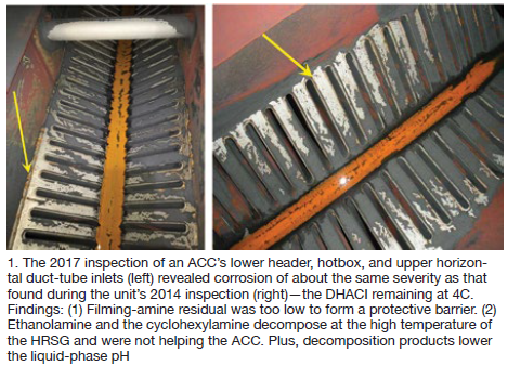
In 2014, improvements were made in the plant’s sampling and analysis panels and a pH target of 9.8 was set using ammonia. After a year of unsatisfactory results at pH 9.8 (iron remained high), the owner/operator attempted to feed a blended filming amine to a target residual but was unable to verify results. The target pH was changed to 9.4.
Treatment was changed in January 2017 from ammonia-only to a 2:1 ammonia/ETA blend, increasing the pH target to 9.6. The blend was eventually changed to 4:1, achieving a pH of 9.2 to 9.3.
As measured in the 2017 outage, the DHACI remained at 4C.
This presentation showed the complexities of filming chemical utilization, noting thermal decomposition of neutralizing amines and difficulties in achieving an optimum feed rate.
Lessons learned included the following:
1. Either increase liquid-phase pH with ETA feed upstream of the ACC (not at the condensate pump discharge), or maintain at least pH 9.8-10 consistently with ammonia at the CPD.
2. Apply standalone LP drum and IP drum pH control with trisodium phosphate (TSP).
3. If using a filming amine or filming product (film-forming substance, FFS), choose one with minimal blended constituents so that target residual can be achieve without dramatic increases in cation conductivity caused by the breakdown of chemicals in the blend.
Saavi Energia. Oscar Hernandez, O&M manager for Saavi Energia, and a member of the user group’s steering committee, discussed fleet-wide system chemistry programs for the Mexico City-based private power producer. Saavi operates several combined cycles—including three with ACCs (El Bajio, San Luis de la Paz, and Chihuahua).
Corporate chemistry guidelines are based on the recommendations of both EPRI and the International Association for the Properties of Water and Steam (IAPWS). One principal objective, Hernandez explained, is an ideal pH level which “must be controlled properly within the recommended range.” He noted two plants with pH targets of 9.4 and 9.6, both showing acceptable iron levels.
Accurate benchmarking, monitoring, and treatment are critical, he explained. The presentation offered details and background on treatment options, monitoring, and diagnostics. Hernandez also described Saavi’s experience with ACC decay tests and finned-tube cleaning methods.
The speaker strongly recommended challenging the cost/benefit claims of contractor-proposed chemical programs (cost versus unit capacity factor).
Emmauel Luévano, a manager at Saavi’s Chihuahua III plant, subsequently reviewed the company’s ACC best practices—including fan start/stop sequencing, fan performance monitoring, vibration analysis, infrared imaging for steam flow distribution, mechanical inspection, etc.
Modifications at Rio Bravo. Hector Moctezuma, Falcon Group, presented on the windscreen project at Central Valle Hermoso, a 500-MW facility added in 2005 as part of the 1490-MW Rio Bravo Energy Park.
Design plant output had been “unattainable during the summer months because of high backpressure. The significant reduction in power output was attributed to ACC under-performance in hot and windy conditions.”
Moctezuma added that “even though the condenser was sized, specified, and supplied correctly, there had been degradation from severe fouling and tube damage. Performance was affected more by higher temperatures and winds.”
The owner/operator considered options and selected a wet/dry parallel condensing system (Fig 2). This was based on considerations that included:
1. ACC enlargement was a very expensive option with marginal benefit, and
2. Additional water sources were available in the vicinity for the limited need.
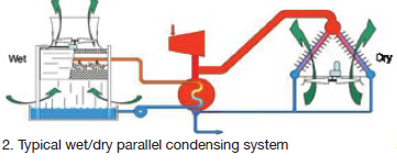
In this system, “exhaust steam is simultaneously condensed in both a wet evaporative and existing dry cooling system.” The goal was to “remove the steam-turbine backpressure limitation during all periods with ambient temperatures higher than 86F—about 1000 hours per year.”
Advantages of the parallel system included:
-
- Combines the performance of a wet evaporative system with the water savings of an ACC.
- Optimizes water use to minimize condensing system costs.
- Sized to meet cooling-water availability.
However, the performance-reducing impacts of local winds remained. Winds were causing an ACC pressure increase of 0.44 to 0.88 in. Hg by reducing fan speed, resulting in a steam-turbine power decrease of 3 to 4 MW. This occurred with wind speeds above 9 mph (1800 hr/yr) and became very significant at speeds between 16 and 19 mph (300 hr/yr).
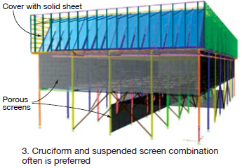
Windscreens were selected to reduce both wind speed and crosswind effects. All available options of type and location were considered. A combination of cruciform and suspended screens was optimal for the atmospheric conditions at the plant. ACC structural reinforcement was needed to comply with Mexican regulations. Screens were installed in May 2018.
Under worst conditions (ambient 86F and winds 19 mph), backpressure and power output improved by 0.59 in. Hg and 1.68 MW.
ACC bundle replacement. Derek Silbaugh, an engineer with Black Hills Energy, reviewed plans to undertake replacement of the tube bundles in an ageing ACC. The multiple issues involved in determining a cost-effective approach for improved performance and long-term reliability are complex but relevant to others in similar situations.
Optimizing windscreens. Cosimo Bianchini, Ergon Research (Italy), offered a comprehensive update on windscreen design and application, entitled “Deficiency reduction after installation of optimized windscreen configuration.”
His presentation included motivations and objectives for windscreens at two 800-MW combined cycles, each with an ACC having nine streets and four cells per street. Screens were installed in 2014 on one ACC to allow greater capacity during hot windy days.
Suspended screens were supplied on the first unit, with performance measured one year before and one year after. Comparisons based on similar ambient temperature, relative humidity, with speed and direction, and backpressure showed an output improvement of 15 to 20 MW with the screens in place. Screens were most effective for wind speeds of 20 mph and below.
Both units were later subjected to CFD modeling for possible improvements, testing a wide range of screen configurations—both ground-based and suspended (Fig 3).
Bianchini’s presentation provided extensive modeling details including variations in screen type and placement. Adding to the complexity, the two ACCs (windscreen options and configurations) could be studied and upgraded independently.
One interesting takeaway was visual representation of the seemingly abundant options.
Bianchini offered the following conclusions:
-
- Optimization of windscreen layout by CFD identifies candidates with much higher performance than the one currently installed. Some options were eliminated because of installation complexity and higher structural loads.
- The selected layout showed capability of recovering 58% of the losses of the downstream ACC capacity compared to the upstream unit.
- A simplified economic analysis showed an acceptable payback period.
Induced draft. Thomas Louagie, SPG Dry Cooling, discussed the emergent topic of induced-draft ACC designs, along with a history of development from traditional A-frame mechanical draft units. SPG offers a W-style heat exchanger arrangement for all sizes of plant output.
Features include SRC© finned tubes (aluminum-clad steel tubes with brazed aluminum fins); fan deck with perpendicular-shaft gearbox, motor, fan, and fan bell on top of the heat exchanger; short fan bridge supported in the middle by the central top manifold; and an accessible fan deck for maintenance.
Two negative effects of wind on traditional ACC performance are recirculation of hot air exiting the ACC, and reduced fan air flow attributed to disturbances at the air inlet. “With the W-style ACC,” explained Louagie, “recirculation is reduced due to higher exit air velocity, and the fan inlet is protected from crosswinds by the tube bundles, acting like screens.”
“Flow-accelerated corrosion can also be reduced,” he explained, “due to lower steam velocities and less steam pressure drop.”
Details presented also showed improved backpressure and higher steam turbine production at low ambient temperatures (below 50F).
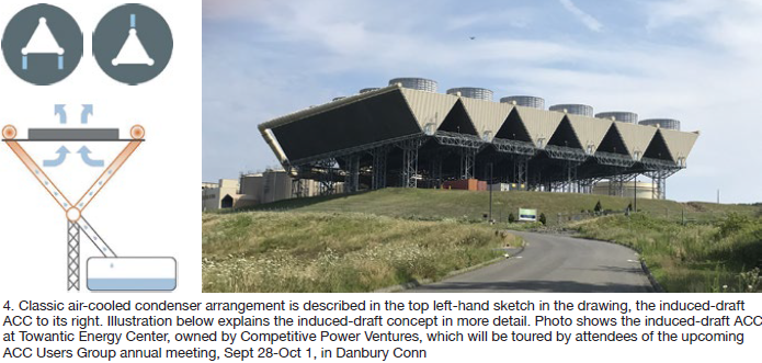
What might be of particular interest to owner/operators is that the ACCUG’s 2020 meeting, Sept 28-Oct 1, at the Danbury (Conn) Crown Plaza will include a tour of CPV’s Towantic Energy Center, which features and 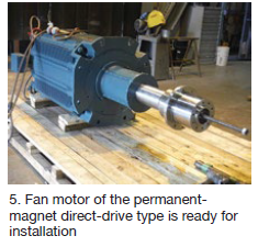 induced-draft ACC (Fig 4).
Direct-drive fans. ABB’s Marty Mates explained the installation and experience with permanent magnet (PM) direct-drive fan motors, first introduced to the wet cooling-tower market in 2008. ACC trial installations began in 2015 (Fig 5).
Mates discussed background development, including feedback from previous ACCUG meetings, beginning in 2012. A prototype project concept installed at Basin Electric Power Co-op’s Dry Fork Station) was reviewed at the 2014 conference. Previous group discussions included reliability, size/weight, gearbox issues, and general maintenance concerns.
Environmental issues (including noise) and parasitic load (efficiency) were also discussed for the new design.
Dry Fork’s prototypes were installed in 2015 and 2016, both rated at 250 hp at 104 rpm. Mates also reviewed the installation challenges and solutions for a recent installation in Jordan.
Wet-to-hybrid conversion. George Budik, global product manager for ENEXIO Dry Cooling, explained that water demands continue to rise, offering an example for plants with evaporative/wet cooling systems. “Each 1 MWh of electricity produced in a fossil power plant requires 600 to 660 gal of makeup water to replace wet cooling-tower losses by evaporation, blowdown, and drift,” he explained. There is, therefore, a trend toward at least considering “conversion to all-dry or hybrid cooling technologies.”
Budik then explained various options, including what he called “the optimum solution,” cautioning that each design is site- and system-specific.
Thermal storage. Ronan Grimes, University of Limerick (Ireland), offered a low-temperature thermal storage concept designed to address the following issues with A-frame ACCs:
-
- The minimum temperature to which turbine outlet steam can be theoretically cooled is ambient air temperature; practically, it is somewhat higher.
- Hot climates impose a thermodynamic efficiency penalty.
- Air in-leakage (efficiency loss) is common.
One approach is low-temperature thermal storage (LTTS, Fig 6) in which a water-cooled condenser (WCC) is combined with a thermal energy storage (TES) tank and air-cooled heat exchanger (ACHEx). The goal is to “exploit the natural ambient temperature variations to condense steam at sub-ambient temperatures.”
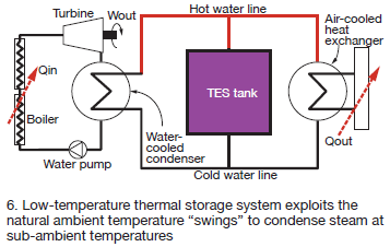
In charge mode (during low ambient temperatures), water is pumped from the tank to the ACHEx, cooled, and returned to the tank for storage. In bypass mode (moderate ambient temperature), water from the water-cooled condenser is cooled in the ACHEx then returned to the WCC. In discharge mode (high ambient temperatures), chilled water is pumped from the tank to the water-cooled condenser where it condenses steam at sub-ambient air temperatures.
Feasibility studies and modeling for this concept are ongoing. One noted case study operated at eight hours of charge, eight of bypass, and eight of charge. Modeling results were explained.
Remote performance management. Sean Cusick, SPG Dry Cooling, followed with ACC360 remote performance management, which provides virtual insight into the performance and health of any air-cooled condenser. Main components are:
-
- Performance analytics that evaluate past, present, and future performance.
- Condition-based monitoring, including vibrational monitors, to predict potential failures.
- Integration of data with weather forecasts.
Cleaning is a must. Consultant Huub Hubretsge addressed the group on various traditional methods of ACC cleaning: high pressure wash, blasting with dry ice, etc. He also explained specific methods of calculating steam-turbine performance loss caused by ACC fouling.
Hubretsge pointed out that these losses go beyond less air available for cooling and reduced heat-transfer coefficients. “If the backpressure at the turbine exhaust increases, the enthalpy of the exhaust steam increases as well (less water in the steam). The higher the enthalpy of steam at the turbine exhaust, the less enthalpy is used for power generation.”
He offered a rule of thumb: “A general rule says that the total power generation will drop 0.7% for every 0.3-in.-Hg pressure increase at the turbine exhaust.”
Sample cleaning/fouling loss calculations were made available to all attendees in Excel spreadsheet format.
For a thorough review of cleaning needs and options, download at no cost Report ACC.02, “Guidelines for Finned Tube Cleaning in Air-Cooled Condensers” at acc-usersgroup.org/reports.
ACC performance enhancement. Andy Howell reviewed the common sources of dry cooling inefficiency (direct-condensing ACCs): steam-to-air heat-transfer efficiency, dependence on ambient temperature, and power requirements for large fans. He then reviewed further inefficiency issues:
-
- Air-side debris accumulation.
- Air in-leakage.
- Wind effects.
- Hot air recirculation.
- Gaps and air bypass.
- Tube fin damage.
All are common discussions at the ACCUG meetings.
Howell also reviewed more specialized topics from past conferences: wet cooling support, air misting (fogging), deluge cooling, and system expansion (adding streets).
He noted that “a variety of performance improvements are available and should be evaluated for cost effectiveness.” In particular, Howell mentioned fan uprates, including some common uprate results for a specific scenario:
1. Auxiliaries consumption increased by about 1.2 MW because of a larger fan-drive system.
2. Complete elimination of back pressure limitation, with a significant and sustained improvement of a least 3.5 in. Hg.
3. Increase in power output because of a reduction in condenser pressure and the possibility of increasing condenser load and steam flow through the turbine.
4. Heat-rate improvement attributed to lower condenser pressure and lower back pressure on the steam turbine (which he called “free power”).
INTRODUCTION
 This two-part report summarizes information on cycle chemistry and thermal transients at combined-cycle/HRSG plants shared at the industry’s leading technical forums worldwide over the last several years—such as the US-based HRSG Forum with Bob Anderson. The foundation for many presentations and discussion sessions on these subjects comes from assessments undertaken in the last decade at scores of plants by Barry Dooley, Structural Integrity Associates Inc, and Bob Anderson, Competitive Power Resources Corp (CPR).
Their work has been compiled in an extensive report, “Trends in HRSG Reliability—a 10-Year Review,” completed only a couple of months ago. Consulting Editor Steve Stultz has greatly condensed its contents to whet your appetite for the extensive guidance offered on HRSG operation and maintenance. This seminal effort tells us that the potential equipment damage mechanisms from improper chemistry and operation are critical and global, regardless of OEM design or plant location. The problems are fundamental, universal, and should not be ignored. You can download the complete report from the CPR website at no cost.
Have questions? Post them in the online HRSG Users Discussion Forum, chaired by Anderson, on the Power Users website (users only, registration required, no cost). Power Users is the umbrella organization serving the Combined Cycle, 7F, Steam Turbine, Generator, and Power Plant Controls users groups.
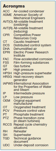
By way of background, Dooley serves as executive secretary of the International Association for the Properties of Water and Steam (IAPWS). It was formed in 1929 and today is an international knowledge base concerned with the thermophysical properties of water and steam, powerplant cycle-chemistry guidelines, and other aspects of high-temperature aqueous mixtures relevant to thermal power cycles. These are the folks who developed any steam tables you have used. Selected IAPWS Technical Guidance Documents (TGD) referenced in this report can be downloaded at no cost from the organization’s website.
Dooley specializes in identifying and resolving damage and failure mechanisms in powerplants, and has global expertise in HRSG tube failure reduction/cycle-chemistry improvement, and FAC programs (see sidebar of acronyms).
Anderson, as principal of CPR, is focused on HRSGs and their related steam-plant auxiliaries in the combined cycle/cogeneration sector of the electric-power industry. Of particular note is his experience in identifying avoidable and damaging thermal transients in HRSGs and their cause/effect with operating procedures. His relationship with Dooley incorporates decades of powerplant analysis, design, and hands-on experience in both system mechanics and chemistry globally.
APWS and related organizations (EPRI, ASME, and several others) keep up with changes in powerplant applications. But all would be first to state that their work is based on the fundamentals and working experience of water chemistry, thermodynamics, fluid dynamics, heat transfer, two-phase flow and circulation, metallurgy, structural analysis, and design.
So, when these experts offer insights on trends we should listen, discuss, and learn.
Part 1: CYCLE CHEMISTRY
A decade ago, CCJ ONsite issued a report by Dooley and Anderson assessing trends in HRSG cycle-chemistry and thermal-transient performance, compiling information gathered from a variety of plants and locations. Their review noted that the frequency of damage and failures in the subject plants had remained almost the same for 20 years. Their latest and much more comprehensive study should leave no doubt about the previous results.
The authors remind us that materials of construction and their long-term reliability depend on internal surface protective oxides. As one primary example (feedwater sections up to about 570F), iron oxide is a passivating protective layer on a metal surface that acts against further corrosion.
Formation of these critical oxides relates directly to the cycle-chemistry treatments used in the condensate, feedwater, boiler/HRSG evaporator water, and steam.
The cycle-chemistry damage and failure mechanisms are all influenced by operating with less than optimum treatments, and doing so results in protective oxide breakdown.
Thus, in a powerplant setting, establishing the appropriate chemistry for the materials involved then exercising vigilance to detect any signs of chemistry upset are required.
The chemistry of the condensate and feedwater is critical to the overall reliability of HRSG plants. Good cycle chemistry is designed to prevent and/or reduce corrosion and deposits in the water/steam circuit, usually initiated and managed through a combination of techniques.
All-volatile treatment (AVT), applied to condensate and feedwater, represents the simplest form of chemical conditioning. The four standard variations are:
-
- AVT(R), all-volatile treatment (reducing).
- AVT(O), all-volatile treatment (oxidizing).
- OT, oxygenated treatment.
- FFS, film-forming substances.
Over time, AVT(O) has emerged as the preferred treatment for HRSGs in combined-cycle plants. For some units, adding solid alkalizing agents to drum/evaporator water might be needed to improve tolerance to impurities and reduce corrosion risks. Common agent methods are phosphate treatment (PT) and caustic treatment (CT).
Some rules of thumb. IAPWS and the authors of the “10-Year Review” tell us that there are now some proven Rules of Thumb, tested by time, location, and operating experience. These are valid for plants where steam and water contact only ferrous materials.
1. An oxidizing treatment—AVT(O) or OT—should be used to prevent single-phase FAC. AVT(R) should NOT be used. And here emerges one of the frustration points. “The global situation is improving, but AVT(R) is still used in more than 30% of units worldwide, reduced from about 70% in the early 1990s,” the report states. This, we are told, is a major reason single-phase FAC is still occurring.
2. An elevated pH with ammonia or an alkalizing amine is needed to control two-phase FAC. A pH of up to 9.8 is recommended.
3. Total iron corrosion products should be carefully monitored to target <2 ppb in the feedwater and <5 ppb in the drums. These levels are achievable if the optimum chemistry is used.
 FAC detection is critical. Corrosion products like to move. FAC, the authors and others have determined, can occur in the preheaters, economizers, and evaporators of HRSGs. Benign corrosion products released by FAC then move to the HP evaporator and deposit on the heat-transfer surfaces. These deposits, when thick enough, can then “act in the evaporators as initiating centers for some of the tube failure mechanisms.” If dangerously thick HP evaporator tube deposits are permitted to accumulate, they must be removed by expensive chemical cleaning to avoid tube failure mechanisms.
Cycle-chemistry adjustments are key to reducing or eliminating both single- and two-phase FAC, causes of significant and costly equipment failures. The “10-Year Review” stresses, “It is most important to identify the type of FAC correctly because the cycle-chemistry solution to arrest single-phase (use of oxidizing treatments) is quite different to that for two-phase (use of elevated pH up to 9.8).”
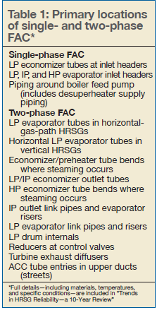
According to the report, most plants address single- and two-phase FAC at the same time from a chemistry application, which is incorrect. The first step is to recognize the primary FAC locations (Table 1). The second step is to find the evidence and distinguish between single- and two-phase FAC. “If these surface features are linked with the location of the FAC, then it should always be possible to identify the correct type of FAC occurring in the HRSG,” the report states.
RCCS. By looking at a large HRSG population over a substantial time period and diverse locations, the report’s authors can clearly determine repeat cycle-chemistry situations (RCCS) that should alert owner/operators to impending damage. In total, there are 10 RCCS associated with combined-cycle plants, and the most common are outlined below (but all should be studied in the published study):
Corrosion products. The authors tell us that correct monitoring of total iron (Fe) within the system should be a priority for any powerplant. Such analysis is key to optimizing a plant’s cycle chemistry, and for lowering the risks of FAC and under-deposit corrosion (UDC). Comprehensive assessments in the latest study uncovered findings such as:
-
- Corrosion product levels were not known. Even if monitored, there were often too few monitoring locations and/or inadequate sampling techniques. And, if samples were taken, analysis was often limited to the soluble part of total iron. Samples should be digested to determine total iron.
- If proper levels were known, they were too high.
 HP evaporators. Corrosion products found on the inside surfaces of HP evaporator tubing should alert owner/operators to corrosion and FAC in the sections of the cycle at lower pressure. Assessments revealed the following:
-
- Owner/operators had no knowledge of deposit levels, even in plants with severe FAC.
- If known, deposit levels were not linked with chemistry in the lower-pressure circuits or to the levels of transported total iron.
- HP evaporator samples from specific locations had not been taken for proper, accurate, and complete analysis.
- Some evaporators had been sampled and needed cleaning, but management had delayed or cancelled the activity.
- If accurate, deposit levels were known, they were too high.
Online instrumentation. IAPWS offers a detailed guidance document on instrumentation for both monitoring and controlling cycle chemistry in combined-cycle plants. However, site reviews found the following:
-
- Instrumentation as a percentage of IAPWS guidance, installed and operating, ranged from 0 to only 60%.
- Many plants used grab samples only.
- Instruments were improperly maintained or calibrated, or were simply out of service.
- Alarms for operators in control rooms were lacking or non-existent.
Air in-leakage. The common problem of air in-leakage (AIL) reduces both plant capacity and efficiency and makes cycle chemistry much more difficult to control. According to IAPWS, “AIL often contributes to subcooling of the condensate and to increased concentrations of dissolved oxygen and other contaminants in the condensate.”
Common sources of in-leakage are condensers, pumps and valves, and instrumentation penetrations, among many others. Detection and maintenance are critical. But detection program reviews showed a high level of site indifference.
Some owner/operators showed little awareness of potential impacts:
-
- At some locations, there were no detection teams or programs in place.
- AIL measurement methods were faulty, no vacuum test had been performed, or inert tracer (for example, helium) was not used.
- If air in-leakage was detected, correction was too often given low priority.
HP drum carryover. This repeat situation is of primary importance to protect the phase transition zone (PTZ) of the steam turbine if contaminants are allowed to enter the cycle. Also, “any condenser leakage will immediately elevate the HP drum and HP superheater chloride levels.”
Categories identified in the survey included:
-
- No carryover testing had been completed since commissioning.
- Plants were not aware of the simple process involved.
- Saturated-steam sampling equipment was non-existent or not operating.
Shutdown/layup protection. Lack of proper protection has led to serious pitting damage in HRSG drums and in steam turbines. Findings included the following:
-
- No equipment had been used for nitrogen blanketing and/or dehumidified air (DHA).
- Layup equipment was installed, but had not been maintained or operated properly.
- Owner/operators did not recognize potential risk to the phase transition zone in the low-pressure steam turbine.
- There was no awareness of potential benefits (or dangers) of using film-forming substances (FFS).
Challenging the status quo. The authors list this category as “perhaps the most important RCCS for damage prevention (arresting FAC and preventing UDC in power cycles).” Some examples:
-
- Reducin
 g agents still being used.
 - Unchanged system chemistry since commissioning.
- Guidelines incorrect or out of date.
- System pH low.
- Chemical addition points incorrect.
- Widespread failure to question the use of proprietary chemical additions (phosphate blends, amines, film-forming substances) or know the exact composition of the chemicals being added.
- Reducin
One interesting note from the report: “Equal results have been found by Dooley in assessments of over 120 conventional fossil plants.”
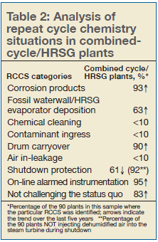
Things that can be addressed. Here is a telling summary statement from the authors: “For plant operators and chemists who want to be on the path to world-class performance, Table 2 provides the most important cycle-chemistry aspects which need to be addressed to ensure they avoid future cycle-chemistry-influenced damage or failure.”
The numbers in the table represent the percentage of plants examined by Dooley and Anderson where the particular RCCS was identified. Arrows indicate RCCS trends industry-wide over the last five years: improvement, no discernable change (no arrow), a step backwards.
The results tabulated illustrate why three major damage/failure concerns (FAC, UDC, and steam-turbine PTZ) continue to occur worldwide despite the excellent understanding of the mechanisms, the well-documented system locations, and the availability of comprehensive guidance available from IAPWS and others.
 New and existing plants. For new plant development, the best way to ensure proper chemistry is to incorporate the suite of IAPWS Technical Guidance Documents into the specification phase, proper chemistry thus becoming part of the plant’s status-quo policies and procedures. This also will help ensure alignment with the three guiding principles of oxidizing treatment, proper pH, and the achievable values of <2 and <5 ppm iron (feedwater and drums, respectively).
Once in operation, owner/operators should focus their attention to the repeat cycle chemistry situations, addressing each with a clear and complete action plan. Such attention should eliminate situations known to cause damage and failure.
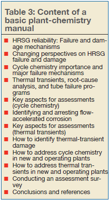
Perhaps most important, each facility should maintain a comprehensive Plant Chemistry Manual that includes the latest cycle-chemistry targets. A suggested table of contents is offered by Dooley and Anderson in their published 2019 study (Table 3).
Part 2: THERMAL TRANSIENTS
The first part of this report offered selected highlights on the damage and failure mechanisms resulting from improper attention to system water chemistry. Part 2, here, continues with a focus on damaging thermal transients. A thorough review of “Trends in HRSG Reliability—a 10-Year Review” will go deep into details, hands-on experience, insights, and assessment methodology. You can download the complete report here at no cost.
Thermal transient damage. In brief form, thermal-transient-influenced damage and failure categories and details are:
HRSG tube failures
-
- Thermal creep-fatigue in HP superheaters and reheaters at tube-to-header welds.
- Thermal fatigue in economizers at tube-to-header welds.
- Tube distortion in economizers, HP superheaters, and reheaters.
- Accelerated thermal aging (overheating) of HP superheater and reheater tubes downstream of duct burners.
- Water/acid-influenced corrosion in LP economizers (feed water inlet temperature).
Steam piping failures
-
- Thermal creep-fatigue in HP superheater and reheater attemperator pipe girth welds.
- Thermal quench cracking in HP superheater and reheater attemperator pipes, elbows, and tees.
- Transient and permanent thermal distortion (hogging and humping) downstream and upstream of attemperators.
- Thermal fatigue in HP superheater and reheater drain pipes.
- Thermal fatigue in girth welds downstream of HP and IP bypass desuperheaters.
- Ageing of pipe downstream of the HP bypass pressure control valve.
HP steam drum damage
-
- Corrosion fatigue at shell-to-downcomer and shell-to-nozzle welds.
Valve damage
-
- Erosion of HP bypass pressure control valve (PCV) seat and plug (from improper operation).
Background. Industry and study backgrounds are presented in Part 1. Regardless of OEM, some level of corrosion (both gas- and steam/water-side) and thermal degradation (creep and fatigue) will occur in HRSG pressure parts.
The report’s authors, Barry Dooley of Structural Integrity Associates Inc and Bob Anderson of Competitive Power Corp, tell us that “the key to reliable operation and long service life is limiting the rates of these damage mechanisms to those anticipated by the designer.”
When the first F-class HRSGs came into service (1990s), contractors, component manufacturers, and owner/operators did not recognize many of the thermal-fatigue damage issues that would or could surface. As one example, few recognized that condensate would form in the HPSH and RH during startup, and drains were not designed to be open during startup.
As another, the ASME Boiler and Pressure Vessel Code did not require performance of fatigue analysis during the design process. Most designers and owner/operators projected ongoing baseload operation.
Beginning in 1998, Anderson (then with Florida Power Corp) and others began studying the temperature impacts on HRSG tubes, pipes, and headers. Many of these findings are referenced in the new report and form the basis for today’s ongoing analyses and system operation reviews.
By 2009, retrofits had addressed some of the problems, including these:
-
- Redesigned attemperators, control valves, and control logic.
- Modifications to HPSH/RH modules to decrease rigidity.
- Modifications to HP/IP economizer headers.
- Replacing original drain pipes with larger pipe sizes.
- Bypassing elevated blowdown tanks at low pressures.
Since 2009, the authors have conducted surveys at an additional 45 combined cycle/HRSG plants throughout the world and have incorporated those findings in their 2019 report.
Operations. Thermal transients in HRSG components are unavoidable. Repeated transients, aggravated by both cycling and low-load operation, can lead to “incremental accumulation of invisible, irreversible fatigue damage in these components during each transient,” according to Anderson and colleagues. The degrees of damage, the assessments tell us, depend primarily on the following:
-
- Size of the thermal transient (both heating and cooling).
- Component design details.
- Material properties.
In turn, each component’s finite fatigue life “is dependent on the degree of fatigue accumulation during each cycle and the number of cycles experienced.” Damage is cumulative. Thus, most failures “are the result of larger and/or more frequent thermal transients than anticipated by the designer.”
Enter today’s environment of repeated cycling, low-load operation, and shutdown.
Can we see it coming? The authors’ experience indicates that most failures result from unidentified or unresolved operational issues, leading to these common occurrences (among others):
-
- Leaking of attemperator/desuperheater spray water.
- Attemperator overspray.
- Insufficient draining of HPSH/RH condensate during startup.
- Inappropriate operation of HP and hot-reheat bypass systems.
- Economizer inlet quench.
New results? Not really. As the authors state, “Unfortunately, many of the avoidable causes of damaging thermal transients identified in 2009 continue to be common findings in these later surveys.” Surveys show persistence of some of the design weaknesses and repetition of non-optimum operating procedures, such as:
-
- Insufficient straight steam-pipe length downstream of attemperator spray nozzles.
- Lack of or improper protective control logic for attemperators and valves.
- Operating procedures that misuse the interstage attemperators during startup and shutdown.
- Attemperator overspray.
- Permitting operators to manipulate attemperator setpoints or manually control spray valves.
- HPSH and RH drain system operating procedures that fail to completely drain during startup.
- Aggressive increase or decrease in HP drum pressure.
A new phenomenon appeared in the HP steam-turbine bypass circuit: Erosion of the pressure control valve cage, disc, and seat by wet steam and water.
How to identify. The authors go into detail on identifying “the most common underlying causes of failures driven by avoidable thermal transients.” Emphasis is on the word “avoidable.”
Attemperator spray water leaking past the block and control valve remains common (82% of 54 plants evaluated). The authors note that small to moderate leaks (seen on DCS data plots) may be viewed as insignificant by operators, but “even a small leakage rate into hot steam pipes during periods of zero to low steam flow causes cracking (1) of thermal liners, (2) at the inner surface of steam pipes, and (3) in girth welds.” Also, temperature differences between bottom and top of pipes can cause distortions that impact even the pipe support system. Water can become trapped in lower areas.
Many systems, the authors say, use master control/martyr block spray valve logic. With many open/close cycles on the block valve, the seat is damaged and the control valve’s seating surface is now exposed to high differential pressure. This arrangement is said to be a major cause of leakage.
Overspray means that not all spray water can be evaporated before the first downstream elbow or tee fitting. Best practice is a minimum 50 deg F superheat at the attemperator outlet. Design issues include insufficient steam pipe length, inferior quality spray nozzles, and improper HPSH/RH heating surface arrangement. Other factors are inferior control logic and operator intervention.
Inappropriate attemperator operation. When steam flow is low or zero and pipes are hot an immediate tube failure is possible because of ductile overload. More frequent damage is caused by (1) spray operation too early in startup or too late in shutdown, (2) manual manipulation of set points, and (3) inappropriately using interstage spray to match outlet steam attemperators for startup of the steam turbine. One suggestion for plants equipped with GE gas turbines is exhaust-temperature matching.
Inadequate draining during startup. Condensate must be drained before initiation of steam flow in the HPSH and RH. During all types of startup, water will migrate and quench some of the tubes if not completely drained. During hot starts, cooler water in the HPSH and lower piping will move upward and enter the hot upper headers, manifolds, and steam piping.
Aggressive HP drum pressure ramp rates. Dooley and Anderson say that “repeatedly cycling the drum near or beyond the maximum permissible ramp rate is likely to result in cracking of the protective magnetite layer, followed by corrosion fatigue cracking of the underlying steel.” Note that if weld repair becomes necessary, both welding and post-weld heat treatment are expensive and time consuming.
Forced cooling. Many owner/operators force-cool the GT and HRSG after shutdown to expedite maintenance activities. “If not carefully managed, forced cooling can impose extreme thermal transients on the HP drum, HPSH/RH headers and piping, and main steam/hot reheat piping,” the authors warn.
HP bypass-valve erosion. Abnormal seat, plug, and cage erosion in bypass pressure control valves has become common regardless of valve manufacturer, “caused by passing wet steam and/or water through the PCV. As damage progresses, superheated steam can leak through and overheat the downstream carbon steel pipe.”
HRSG designers have long suggested that cooling steam flow be initiated in the HPSH/RH “as soon as possible.” The surveys show an increase in control logic accomplishing this by immediately opening the PCV at GT light off during startup, or before the main steam pipe upstream of the PCV is properly heated. The authors suggest that “as soon as possible” should not require unacceptable damage to the bypass system. Few plants are equipped with permanent instrumentation to measure steam temperature at the PCV.
Ranking the key causes. The authors’ original paper, issued in 2009, ranked 55 potential causes of damaging thermal transients. Many have since been addressed through improvements in equipment design and operating procedures. But serious causes remain, and Table 4 presents the most important by category. As for Table 2, the numbers represent the percentage of plants and the arrows indicate trends.
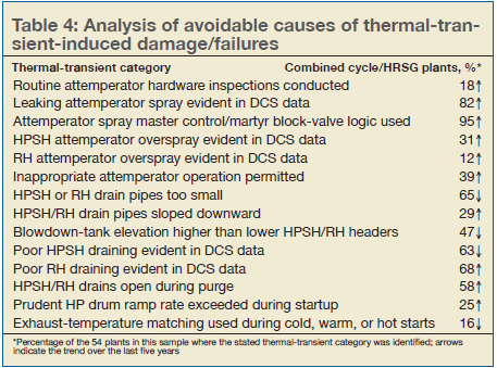
Avoidance. The authors clearly and comprehensively address strategies for avoiding damage in both new and operating plants. These strategies are summarized below.
Leaking spray water. Dooley and Anderson suggest a reverse logic for valve protection, to a master block/martyr control valve logic and an attemperator system release permissive that results in the block valve opening only during startup just prior to first attemperator use, and closing only prior to GT shutdown.
Overspray and inappropriate operation. Overspray strategies include equipment and maintenance upgrades, properly designed and tuned cascade control systems, prohibiting operators from manually adjusting setpoints or operating spray valves, and ensuring an overspray protection feature on system controls to maintain 50 deg F of superheat at the attemperator outlet.
Failure to adequately drain. Key steps in effective drain modifications include calculating the rate of condensate formation, and determining the minimum drain pipe sizes and arrangements. The section on automatic drain control in the 2019 report lists features that should be included in the modifications—such as slope, blowdown tank location, use of thermocouples, installation of an effective automatic drain valve system, and compliance with personnel safety and/or environmental protection practices. Proper procedure results are noted.
Aggressive drum-pressure ramp rates. Legacy units may not have been provided with suitable ramp rates. The authors note that “it may be necessary to hold GT load at a low value for some period during cold/warm startup to avoid exceeding safe HP-drum ramp rate limits. HP bypass and HP sky vent availability and capacity are key factors in complying with drum ramp rate limits later in the startup.”
HP bypass valve erosion. Although not a thermal transient, this common problem is discussed and several suggestions listed including: “delaying opening of the HP bypass PCV until steam temperatures upstream and downstream of the HP bypass branch tee have increased above saturation temperature during startup.”
 The first meeting of the Australasian Boiler and HRSG Users Group (ABHUG), held last fall (2019) in Brisbane, Australia, followed 11 annual meetings of AHUG (Australasian HRSG Users Group). The added B is for boilers. Content now includes conventional fossil-plant technologies and issues closely related to those involving heat-recovery steam generators in combined-cycle and cogeneration systems.
ABHUG is an interactive forum for the discussion of new information and technologies related to HRSGs and boilers—including case studies of plant issues and solutions. The event is supported by the International Association for the Properties of Water and Steam (IAPWS) and its national committees in Australia and New Zealand.
The 2019 agenda featured 21 presentations plus a comprehensive workshop on welding, which included segments on ligament cracking in superheater headers, cold repair of Grade 91 materials, and modifications to HRSG ducting.
Updates also were provided for system chemistry, instrumentation and FAC, and thermal transient issues for attemperators, condensate return and superheater/reheater drain management, and bypass operation.
One shared HRSG/boiler issue is layup and offline protection, increasingly common to all operating systems that make way for the growth of renewables. Improper shutdown and layup procedures are now a standard topic at these industry events.
What follows is an insight into some of the shared challenges.
Pitting corrosion at Tarong. The 1400-MW Tarong Power Station in Queensland was commissioned in the 1980s with four subcritical coal-fired boilers, each rated at 350 MW. The primary reheater is located in the back pass, composed of two sections with horizontal tube elements—126 total elements across each boiler’s width. Design steam conditions at the headers are 935F at 765 psig (610 psig operating).
In 2012, owner/operator Stanwell Corp announced plans to shut down two units for two years because of reduced demand and low wholesale electricity prices. When the cost of natural gas rose in 2014, Stanwell returned the units to service.
Following a Unit 3 major outage in 2018, four reheater tubes across different elements experienced primary failures. Two months later, another two tubes across different elements experienced similar failures (Fig 1).
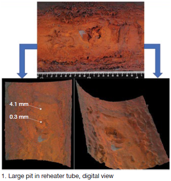
An EPRI roadmap was used to identify, evaluate, and solve the boiler-tube failure issue—EPRI Technical Report 3002010388, “Boiler and heat recovery steam generator tube failures: theory and practice.”
Stanwell adopted the process described in the EPRI document to determine the following:
1. Primary failure location.
2. Primary failure mechanism.
3. Primary failure root cause.
4. Factors contributing to the primary failure mechanism.
Both visual and tube-removal analyses revealed the key factors and mechanism:
-
- Corrosion only in the bottom half of the tube.
- Partial or complete through-wall pitting corrosion on welds and randomly on tube parent material.
- Pit sites open or filled with reddish or reddish-brown corrosion products.
In this case, all pit sites were located in the center sections of horizontal tubes (Fig 2). There was no external erosion, apart from steam erosion, attributed to the primary failures. Stanwell’s conclusion: Pitting corrosion attributed to inadequate layup was the primary failure mechanism.
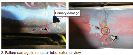
Investigations included metallography, water sources and system chemistry, shutdown procedures, reheat spray operations, and pressure excursions.
Stanwell’s G Wang stated the primary failure root cause as “condensate formed during shutdown. The accumulation of condensate at the bottom of the tubes with oxygen being subsequently introduced during the shutdown provides a stagnant oxygenated-water environment for pitting initiation and development.”
Wang also reviewed relevant contributing factors:
-
- History of shutdowns, durations, and long-term preservation practices.
- Chemical excursions (condenser leaks, for example).
- Corrosion at welds caused by weld/tube galvanic attack.
- Sagging at center of horizontal tube elements.
- Pressure excursions.
- Lack of protection during washdown after tube failure events.
Stanwell’s long-term strategy includes repair/replace option reviews, enhanced inspection methods, and a direct action for shutdown of “drying the tubes before condensate formation and maintaining RH below 35%.”
Wang then listed specific future inspection methods:
Welds. Cobra PAUT/ToFD (ultrasonic phased array and time-of-flight diffraction) ultrasonic.
Tube parent material. EMAT and FMC/TFM (electromagnetic-acoustic transducer and full-matrix capture/total focusing method).
During discussions, Structural Integrity’s Barry Dooley stressed the benefits of “sharing issues across combined-cycle and conventional fossil plants. Corrosion can be initiated during inadequate layup. This and other presentations illustrate just how severe pitting damage can be for both combined cycle and conventional units.”
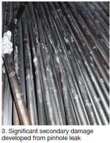 Kogan Creek Power Station (CS Energy Australia) is a 750-MW supercritical coal-fired unit in Queensland, commissioned in 2007. In 2018, a tube leak occurred in the horizontal reheater section of the boiler, causing significant secondary damage and an 11-day forced outage. Fifteen tubes were replaced (Fig 3). The primary failure was a pinhole leak that developed near the middle of the horizontal run, at the bottom of the tube. The failure mechanism was identified as pitting corrosion.
Galvanic corrosion caused by moisture and oxygen led to rapid pitting. CS Energy’s Luke Smith explained that “the base of the pit, low in oxygen compared to the wet metal surface, became anodic. This occurred during shutdown when steam was allowed to condense (not during operation). In this particular case, a low level of sulfate also was present.”
In 2019, the entire reheater was replaced (three banks of 196 elements), extending an outage from 56 to 77 days.
The long-term prevention objective is to replace dry steam with dry air (dry storage). Smith explained that “once the reheater has had about five changes of volume, the HP bypass is opened to allow air to flow to the superheaters. The flow of dry air will be maintained for the duration of the outage if possible. We aim for an RH below 30%.”
This was followed by participant discussion on use of dehumidified air (DHA) for systems including reheaters and steam turbines. Dooley again offered input: “Unfortunately,” he said, “the application of DHA is usually added after the damage has occurred, instead of proactively beforehand.”
AGL program. Stewart Mann, responsible for asset integrity at AGL Energy Ltd, discussed the corporate-wide approach to boiler-tube failures at both gas- and coal-fired steam turbine units.
The AGL tube-failure reduction program records each failure mechanism and root cause, the specifics of each repair, and all planned actions.
The approach discussion raised many logical but often bypassed steps needed for a complete analysis program. First, the AGL program is based on the model in EPRI Report 1013098, “Integrated boiler tube failure reduction/cycle chemistry improvement program (2006).” Second, it is produced as a fleet-wide AGL standard. Third, it is now integrated with AGL’s cycle-chemistry standard.”
The goal is to apply risk-based systems to minimize repeat failures, reduce failures from new mechanisms, and decrease the number of failures at new locations for known mechanisms. As Mann stated, “Unless we have recently changed how we are operating, credible inspection and analysis should enable us to confirm whether a potential mechanism is an issue at our plants.”
Data gathering includes failure mode and mechanism, root cause, extent of damage to the tube with the primary failure, tubing in the vicinity of the primary failure (secondary damage), and the surface areas along the leaking tube.
“AGL is careful to preserve removed tubes for metallurgical examination, and to always consider possible removal of additional samples,” added Mann. Also, every repair has strict QA provisions for:
-
- Welder certification.
- Inspector certification.
- Welding procedures.
- Welding materials.
- Selection of tube materials.
“All of this,” he continued, “requires good collaboration among trading, operations, and engineering.”
Each ALG site now has a dedicated boiler-tube failure-reduction program team that includes:
-
- Site boiler engineer (lead).
- In-service inspector.
- Principal engineers from the company’s technical services group.
- Operations input.
- Maintenance input.
- Complete failure and inspection history reviews.
- Development of inspection strategy and action plans.
“All reports are finalized, distributed, and accessible to everyone,” he said.
Mann offered an interesting concluding challenge: “Play devil’s advocate, and be prepared to question any prevailing norms.”
A common tube-failure approach. Pitting issues from improper shutdown protection can affect both the HRSG and the steam turbine, as discussed in the recently released report “Trends in HRSG Reliability: A 10-Year Review,” by Barry Dooley and Bob Anderson of Florida-based Competitive Power Resources.
In that report, the authors discuss the importance of root-cause analysis and HRSG tube-failure (HTF) programs. They caution that a tube failure often is assumed to be a bad weld, but warn that if tube removal and analysis are not performed the problems will likely continue.
This review continues: “In many cases the actual root cause may be due to a cycle chemistry deficiency, design feature, or operating practice that has repeatedly inflicted corrosion, corrosion fatigue, or thermal-mechanical fatigue damage in the failed tube and its neighbors.”
It is indeed complex. “The only way to ensure that the corrective actions are taken and will prevent a tube failure from recurring is to remove the initial failure site, have the actual failure mechanism identified via a metallurgical laboratory analysis, then determine the root cause of the failure.”
The tube failure discussions at ABHUG were examples of effective root-cause analysis.
Also common: chromium risk. Chromium is a common alloy element in stainless steels and high-chromium-containing materials in steam turbines, steam turbines, boilers, and HRSGs. It is a transition element (metal) with multiple oxidation states.
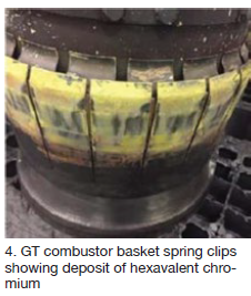 Chromium III is essential for human health; Chromium VI (hexavalent chromium) is extremely toxic. Chromium VI is also easily managed with standard industrial hygiene and personal protection strategies applied, combined with neutralization where needed.
Risks associated with welding of high chromium materials are well understood in the industry, as are possible hazards during some chemical cleaning procedures.
Recently, however, hexavalent chromium has been identified on gas-turbine hot-gas-path components (Fig 4), steam-turbine hot external components (bolts), and on the external surfaces of hot HRSG/boiler piping.
For gas and steam turbines, there’s a link to calcium-containing anti-seize pastes often used on hot components.
The yellowish appearance can be misinterpreted as sulfur deposits from the fuel. “Bright yellow HRSG gas-side deposits should be considered a major warning sign, and treated with significant caution,” cautioned David Addison, principal, Thermal Chemistry Ltd (New Zealand).
Although understood and manageable, this alert involved one particular slide labeled “unconfirmed risk areas”:
Upper and lower crawl spaces with:
-
- High-chromium pipework.
- High-chromium liner places.
- Oxygen atmospheres.
- High temperatures.
- Insulation containing calcium oxide.
- Potential for rain water ingress that allows for calcium leaching.
For HRSGs:
-
- Superheater/evaporator upper and lower crawl spaces.
- GT exhaust ductwork—mainly on the insulation side of plates.
A relatively common major repair encountered by generator owner/operators is replacement of the stator winding. There are two general methods for designing/constructing stator windings, Jamie Clark of AGT Services Inc told attendees at the 501F Users Group’s 2020 Conference and Vendor Fair, last February, at the Hilton, West Palm Beach, Fla. They are:
-
- Conventional: It uses stator bars that are fully impregnated with resin and the resin is fully cured. The assembly materials—for example, fillers and wedges—are dry, thus there is no bonding between the slot contents and the stator iron.
- GVPI (global vacuum pressure impregnation): It uses stator bars on which the groundwall is “dry”—that is, essentially mica tape with no resin material applied. The wound stator is then placed in a large tank where a vacuum is applied to remove all moisture and air from the groundwall. Next, the tank is filled with resin and pressurized to force saturation of the groundwall with resin. Finally, the stator is removed from the tank and placed in an oven to cure the resin. With this system there is strong bond between the slot contents and the core iron.
There is a third type of winding sometimes used that is “almost” conventional versus GVPI. It is intended to reduce material and labor costs in the factory, but it does not consider repair complexity in the powerplant. In this system, the bars are installed fully cured, but there is a saturated “wet” filler in the bottom of the slot and between the bottom and top bars.
Additionally, during the stator wedging process, another layer of saturated felt is installed under the wedges. After baking, the excess resin in the wet fillers fully bonds the slot content to the core iron and the winding behaves as if it were GVPI’d. Adding wet filler beneath the stator wedges makes routine stator rewedging more complex and actually increases the risk of top-bar insulation damage. But that’s a topic for another time.
The replacement procedures for a conventional winding are well understood and straight forward—and stator rewinds have been routine for about a hundred years. GVPI windings became common on large generators recently, and because removal of a bonded winding tends to be very difficult, standard removal procedures have not yet been developed.
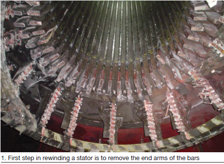
However, AGT has successfully rewound several stators with GVPI windings, and described its procedure for winding removal to the 501F users. A summary of that presentation follows:
The first step is removal of the end arms of the bars (Fig 1). In a conventional winding, bars are lifted by a sling (Fig 2). But with a GVPI winding this succeeds simply in kinking the bar near the core end. However, it has been found that the insulation on the top and side of the bar can be safely removed using a high-pressure water jet (Fig 3).
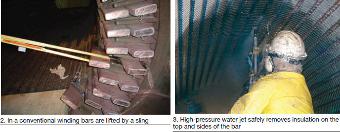
Alternatively, but a bit more time consuming, the bar’s top layer of insulation can be destructively removed and the stator-winding strands can be “peeled out”, either in groups or one-by-one. Certain bar configurations may have single, wide strands simply layered on top of each other, much like a generator field winding. But generators with high ratings may have configurations of multiple-strands wide by many strands high—for example, six strands wide × 20 strands tall. Peeling is relatively easy in the first case, the second not so much.
It may be questioned that the core lamination insulation will be damaged by the high-pressure water jet, and it is certain that the insulation on the edges of the laminations will be impacted. However, the voltage is very low and industry experience with multiple methods of stator-core slot cleaning and repairs, followed by “suitability for service” testing to industry-acceptance criteria for core iron/insulation, confirms that interlaminar insulation remains unaffected.
The water jetting process is restricted to the slot sides and bottom, and both the water jet tip and pressures are specifically chosen to effect only removal of the epoxy. Since some slots are very narrow, this can complicate removal methods and, in some instances, use of a precisely selected rotating tool (specific wheel material, size, depth control, etc) may be required.
As with all stator rewinds, conventional or GVPI, once the process is completed, the entire stator undergoes standard acceptability testing—including high-flux and EL CID testing.
With the bar insulation removed, the bars can be extracted with some difficulty using procedures similar to those used on a convention winding (Fig 4). Once the bars are out, the core can be cleaned with dry ice, vacuum, and/or brushing. Dry out will be needed and full flux core test advisable.
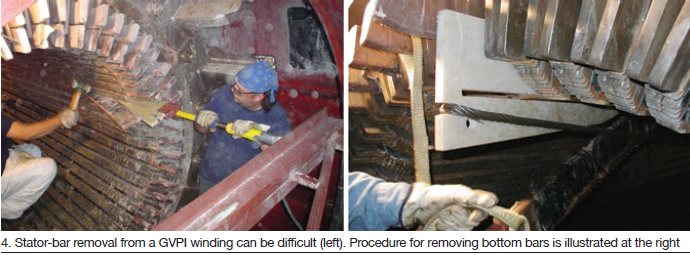
After the core is clean and dry, and has satisfactory flux test results, winding installation can proceed as with a normal winding
Acknowledgement: Clyde V Maughan contributed to this article.
The 7EA Users Group has joined Power Users, the umbrella organization for managing and coordinating the technical programs for many of the electric power industry’s leading user groups—including 7F, Combined Cycle, Steam Turbine, Generator, and Power Plant Controls. Sheila Vashi (sheila.vashi@sv-events.net) of SV Events will coordinate the 2020 conference and vendor fair at the J W Marriott Houston Galleria, October 19-22.
2020 7EA Users Group meeting in Houston, October 19-22
J W Marriott, Houston Galleria
Houston, Tex · October 19-22
Steering Committee
Dale Anderson, East Kentucky Power Co-op
Tracy Dreymala, EthosEnergy, San Jacinto Peakers
Guy LeBlanc, First Energy Group
Tony Ostlund, Puget Sound Energy
Mike Vonallmen, Clarksdale Public Utilities
Lane Watson, FM Global
The 7EA gas turbine’s many attributes—including generally high reliability and availability, and good efficiency in a wide range of applications on a variety of fuels—help make it the most popular mid-size (nominal 85 MW) industrial gas turbine. There are said to be about 1200 of these machines in service.
Annual conferences of the 7EA Users Group attract upwards of a hundred attendees, representing owner/operators from across the globe, to share experiences. Inspections and overhauls typically are a focal point of interactive discussions among users. Virtually everyone in the room wants to know what issues to be aware of, where they are likely to occur, what the indications look like, how frequently their engines should be inspected, etc.
Inspection findings. At the 2019 meeting, last fall in Louisville, the editors spoke to Mike Hoogsteden, director of field services for Advanced Turbine Support LLC, which inspects scores of these machines annually, to learn how users can make their outages more productive and minimize the possibility of missing something that could contribute to a forced outage.
A good place to start, he said, is to review the OEM’s Technical Information Letters (TILs) pertaining to the 7EA, take notes, and bring your questions to the next user-group meeting. Your colleagues and participating suppliers are the best source of advice on what’s important and what’s not, Hoogsteden added. The knowledge gained will help you plan the optimal outage for your gas turbines.
Five TILs he suggested users become intimately familiar with are these:
1884, “7EA R1/S1 Inspection Recommendations,” which addresses the need to inspect R1 and S1 airfoils for possible damage caused by clashing—the unwanted contact between S1 stator-vane tips and R1 rotor-blade roots during operation.
1980, “7EA S1 Suction Side Inspection Recommendations,” which advises users to inspect for crack indications on S1 vanes made of type-403 stainless-steel, regardless of whether clashing damage is in evidence on S1 and R1 airfoils.
1854, “Compressor Rotor Stages 2 and 3 Tip Loss,” which suggests blending and tipping to mitigate the impact on availability and reliability of R2 and/or R3 tip loss. This TIL supplements information provided by the OEM in the O&M manual provided with the engine.
1562-R1, “Heavy-Duty Gas Turbine Shim Migration and Loss,” which informs users on the need to monitor the condition of compressor shims and corrective actions available to mitigate the risks of migrating shims.
1744, “S17, EGV1, and EGV2 Stator-Ring Rail and CDC Hook Fit Wear Inspection,” provides guidance on the repair of dovetail wear and suggests hardware and software enhancements available to mitigate the potential risk caused by operating conditions that promote such wear.
There are many more TILs that demand your attention, to be sure. One is 1090-2R1, “Compressor R17 Blade Movement.”
Blending to Stage 11. When compressor inspections point to the need for blending to remove stress concentrations or cracks that could contribute to the liberation of a blade or pieces of one, Hoogsteden recommends it be done in-situ. This saves time and cost by limiting the extent of unit disassembly required to make the repair. He said that Advanced Turbine Support is now able to perform in-situ blending on 7EA compressor rotors from the inlet guide vanes to Stage 11.
Summaries of several other presentations made last year follow.
Emerson’s Patrick Nolan, well respected by GE 7EA users for his knowledge of the gas turbine and its control, focused on fast starting and fast loading of a simple-cycle engine to take advantage of market opportunities created by recent industry changes. While starting in 10 minutes or less and/or loading at up to 30 MW/min can create new revenue opportunities, he noted, the lifetimes of hot parts would be reduced. There is no free lunch.
Nolan’s charts compared a typical 12-min normal start to a fast start of about 8 min possible with control-system modifications. Stepwise, the fast start he described would look something like this:
-
- Start to purge speed, less than 0.5 min.
- Purge, 1.5 min.
- Ignition and warmup to reach 25% speed, less than 0.5 min.
- Acceleration from 25% to 100% of rated full load, about 5 min.
- Synchronization, about 0.5 min.
Taking advantage of NFPA-85 purge credits on shutdown, which requires additional, but affordable hardware, eliminates the need for a startup purge, saving significant time when trying to satisfy market demands.
Logic to test field devices when the turbine is in standby and receive positive feedback that the entire control system is functional also is required. The owner/operator is responsible for evaluating the safety associated with this activity and when to perform testing, given any operational constraints.
Old GCB made new. There’s often no substitute for the experience gained at user-group meetings. Consider the case history, presented by a West Coast utility at the 2019 7EA conference in Louisville, on the rehab and upgrade of a 35-year-old main generator circuit breaker (GCB) that simply wore out after three decades of dependable service.
You probably could count on one hand the number of plant personnel who had seen the GCB out of its cabinet since COD. So why would you expect someone on the current staff to know anything about this piece of equipment and how to troubleshoot it, and then what to do when a subject matter expert said it should be replaced?
There almost always are options. In this case, you could buy new—the easiest, and most expensive, option—or you could rehab and upgrade the superannuated breaker and save, perhaps, 75%. A pitfall of buying new is that it likely would require a new cabinet, new foundation, etc. Old-made-new allows use of existing infrastructure and you just pay for the breaker.
Here’s what was involved in this project:
1. Pull the old 15-kV GE Magne-blast circuit breaker from the cabinet (Fig 1) and ship to National Breaker Services (NBS) for rehab and upgrade (Fig 2).
2. Rebuild as a modern vacuum breaker and return to the plant (Fig 3).
3. Roll the NBS Citadel-4000 breaker into the cabinet without having to make any changes to the existing infrastructure (Fig 4).
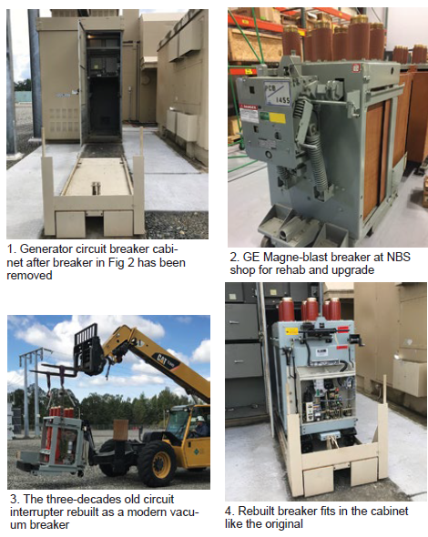
Inlet and exhaust systems, when neglected, are gas-turbine performance thieves. Jeff Cozeby and Laqunnia Lawson identified for 7EA users some of the problems Schock Manufacturing finds when performing inspections on, and making repairs to, these systems. The presenters piqued the interest of conference attendees by offering free inspections through the company’s website.
Cozeby and Lawson began by pointing to corrosion and dirty-air bypass as major contributors to problems found with inlet filters and the inlet duct system. They typically trace the source of these problems to poor design and lack of maintenance and housekeeping. Telltale signs of trouble include corrosion, loose internal parts, leaking gaskets, failed expansion-joint belts, loss of fill in silencer panels, among other things.
The heart of the exhaust ducting, the pair continued, is the internal liner and insulation system. When not properly designed and/or maintained, or repaired improperly, failures occur. Among the things Schock personnel look for during an inspection are casing hot spots (paint peeling or discolored), sheared or broken studs, exposed insulation, liner cracks, wear and tear of expansion joints, gasket failures at access doors, and loss of fill in silencer panels.
The speakers showed more than three-dozen photos to illustrate their points, providing attendees a valuable library of findings to make operator rounds more meaningful. The key takeaway was for staff to catch problems early when repairs usually are easier and less expensive to make.
Busduct replacement. A utility user provided an overview of a project involving replacement of rectangular non-seg busduct with circular non-seg busduct at two generating units in the Midwest. The former was susceptible to failure from water ingress (Fig 5); water would pool on the top of the busduct and leak inside at joints. Over the years, electrical shorts became more frequent. First corrective action was to replace internal duct insulators with ceramic ones. This worked, but only for a while.
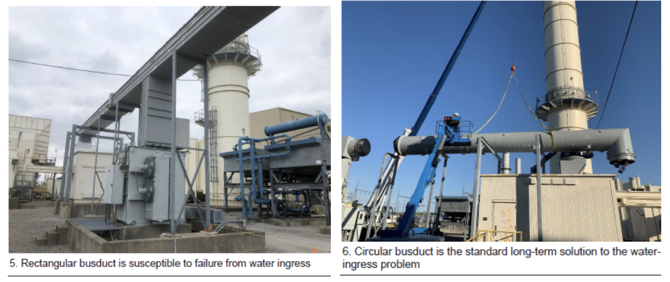
The speaker said circular non-seg busduct had evolved as the industry’s standard long-term solution to the water-ingress problem (Fig 6). He offered the following advantages of circular busduct over the rectangular configuration:
-
- Geometry allows it to shed water quickly.
- All flanges are welded, not bolted.
- The connections between the duct and stationary items (generator circuit breaker, step-up transformer, and generator) are flexible, thereby reducing vibration stress points (Fig 7).
- Aluminum housing resists rust and corrosion.
- Reuse of the existing busduct structures was possible with only new mounting hardware.
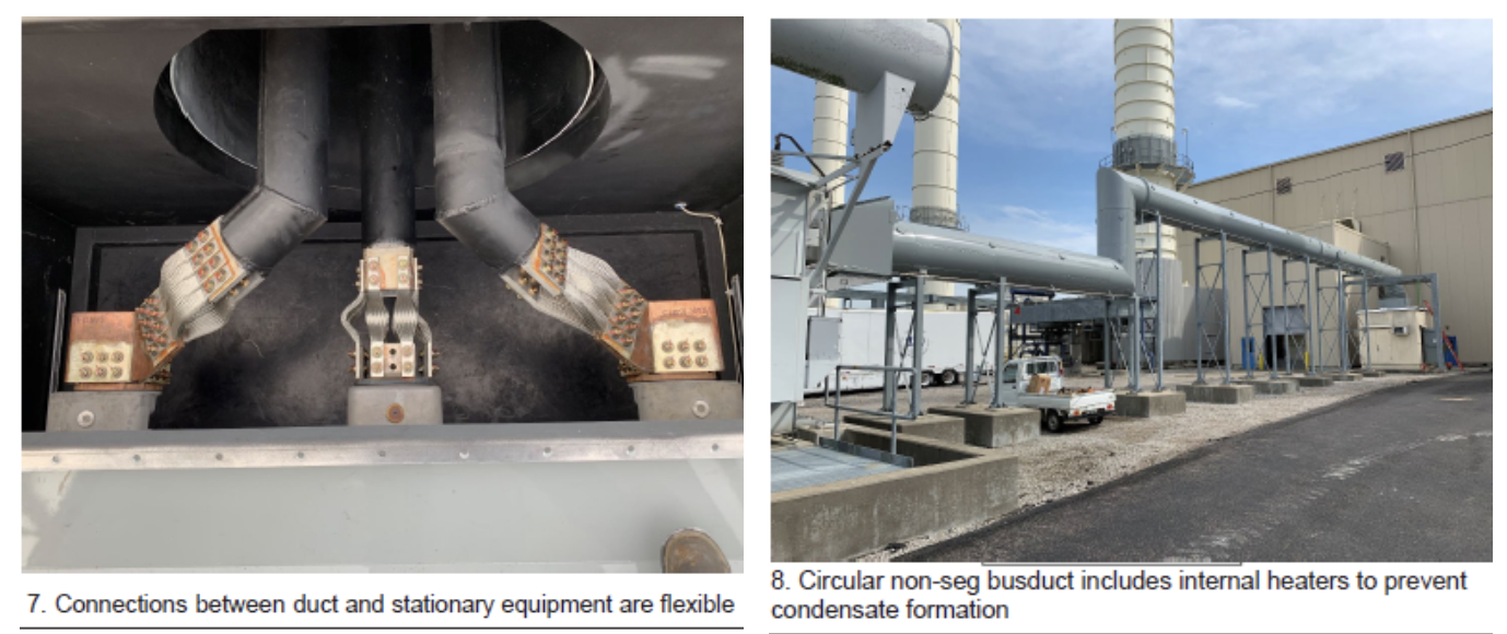
Crown Electric was selected to manufacture and install the circular bus, which included internal heaters to prevent condensate formation (Fig 8). As to schedule, the speaker said equipment was delivered to the site about three months after the purchase order was issued. Demolition of the rectangular busduct and installation and commissioning of the circular replacement took two weeks.
Special to CCJ Onsite
By Benjamin Emerson, Jared Kee, and Tim Lieuwen, Turbine Logic;
Bobby Noble and Leonard Angello, Electric Power Research Institute;
Dallas West, ENMAX Energy
Editor’s note: This article introduces a novel combustion-dynamics monitoring (CDM) algorithm and a case study to demonstrate its successful detection of a gas-turbine combustor fault which otherwise might have done extensive damage to both the combustor and hot-section components. Failures of this type often develop from small, insipient faults which produce subtle signatures in the dynamics data.
Fault signatures can be detected by advanced monitoring algorithms to identify them before parts fail and force the unit out of service. The CDM algorithm described here blends data analytics and combustion domain expertise with existing combustion monitoring data. It currently is fielded on a fleet of frame units and has successfully caught several faults at sufficiently early stages to plan repairs without a forced outage.
Some of the most-costly forced outages are those that stem from failures in the gas-turbine hot section. These failures are particularly catastrophic when they compromise the turbomachinery. While the power turbine is subject to its own failure mechanisms, it is also vulnerable to debris from combustion-system failures.
Typical lean premixed frame-engine combustion systems have several parts that tend to degrade and fail—including the transition piece, combustor liner, TBC coatings, cross-fire/cross-flame tubes, and fuel injection/premix hardware. The last includes dual-fuel nozzles, center bodies, swirlers, and numerous other components depending on the engine make and model. All of these parts have limited lifetimes because of the harsh operating environment, and unwanted phenomena such as flashback, autoignition, and combustion dynamics.
Failures produce fault symptoms—such as issues with operability and emissions, tuning challenges, elevated temperature spreads, and “drifting” combustion dynamics in one or more combustors. When these symptoms are not recognized, the part eventually fails catastrophically and the unit trips because of the loss of one or more combustors, or of the power turbine. Combustion dynamics often provide the earliest symptoms of such issues.
Permanent CDM systems on can-annular frame engines typically include a sensor for every combustor can to measure acoustic pressure. The OEM or third-party monitoring software reads the time-dependent pressure signals and periodically implements a fast Fourier transform (FFT) to convert them into frequency-dependent spectra. These spectra are partitioned into several bands, or bins, within which the software monitors for the peak pressure amplitude and its corresponding frequency. The “bin data” are stored in the historian.
Combustion-dynamics bin data are used for tuning by both manual tuners and automated tuning systems. In addition, the data provide these two opportunities:
-
- Detect and prevent dynamics levels that would threaten the hardware—that is, the dynamics are monitored to ensure they don’t become too loud and cause damage.
- Monitor dynamics data for symptoms of existing faults.
Combustion dynamics are very sensitive to faults such as (1) cracks that change flow paths, and (2) premixer damage that affects flame shape. Thus, CD can be monitored for small changes (amplitude increases or decreases) or frequency drifts that might indicate the early stages of a component failure. Some operators use trending or advanced pattern recognition software to monitor for these symptoms.
The EPRI and Turbine Logic team has developed and patented a CDM algorithm that detects these symptoms and runs continuously and autonomously without any model-building or retraining: The algorithm continuously trains and retrains itself. In addition, the algorithm can distinguish among instrumentation faults, hardware faults, and tuning issues.
The health algorithm consists of a data conditioning step, a non-uniformity check, and an anomaly check (Fig 1). The first identifies and handles instrumentation faults and other issues with the data stream. The non-uniformity step finds the combustion-dynamics signature of the unit during recent times that matched the current operating conditions. Finally, the anomaly logic analyzes the past and present CD signatures of each combustor to identify anomalous behaviors.
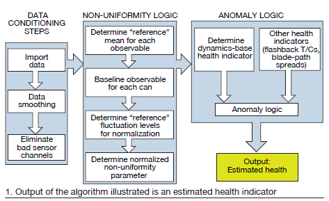
Dynamics signatures come from the bin data (peak amplitudes and their frequencies). Anomalous behaviors are defined as a deviation of one combustor’s dynamics signatures compared to its peers and its past. The peers are the other combustors on the engine. An anomalous behavior may include situations where a combustor becomes louder, becomes quieter, or exhibits a frequency drift compared to the other combustors and compared to its past behavior. Note that a quieter combustor does not necessarily indicate a healthier system!
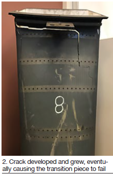 The output of the algorithm is an estimated health indicator, which is a statistical representation of the severity of the outlier. When a combustor has outlier dynamics behaviors relative to its past and its peers, this can be explained by either an instrumentation fault or a hardware fault. The former may include condensation in standoff tubes, cable connector wear, or probe failure.
Hardware faults include any alteration to the combustor hardware—including cracks, leaks, and melting. For a given unit, dynamics signatures often can be paired with a particular probable hardware fault based on experience collected across the fleet. This experience is collected into a fault matrix, which is currently available for 7FA and 501F units.
The net result of this algorithm is an indication that a combustor is “changing,” which can be indicative of an instrumentation fault or an early symptom of a hardware fault. Instrumentation faults can be distinguished from hardware faults, and the hardware fault can often be pinpointed using a fault matrix.
Common catches. The monitoring algorithm described is designed for any can-annular gas turbine with a CDM system. However, the monitoring teams at EPRI and Turbine Logic historically have applied it most often to 501F and 7FA units and have gained experience with the combustion-system faults that the algorithm most commonly catches in these units.
Some of these catches have been predictive during live monitoring, while others have been “postdictive” catches in historical data to develop and demonstrate the algorithm, as well as to identify the time where the fault began to noticeably manifest itself. The most common catches for 501F units have been cracks in transition pieces and combustor liners; in 7FAs, fuel injection/premixing hardware damage.
Case study. An ENMAX Energy plant had experienced a significant force outage attributed to a gas-turbine component failure. What happened was that a crack developed in a combustor transition piece that grew until the component failed completely (Fig 2). In 2017, EPRI began providing monitoring services to the plant in an attempt to prevent future combustion-dynamics-related gas-turbine failures.
During the first year of the program, the algorithm detected abnormalities in the combustion dynamics data from one of a 501F engine’s combustors (Fig 3). The team reviewed the data in collaboration with the plant to rule out the possibility of an instrumentation fault, and subsequently concluded, with a high degree of certainty, that the combustion-system hardware had suffered damage.
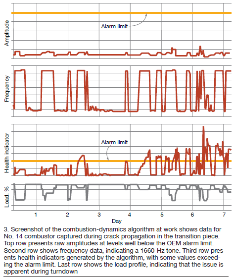
Because the CDM algorithm is sensitive to hardware faults at very early failure stages, the plant had time to manage the issue. A borescope inspection during the next planned outage confirmed the suspected combustor damage, validating the algorithm (Fig 4).
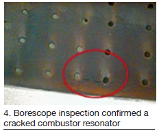 Plant personnel approached the OEM with the borescope images and were assured that the machine could continue to operate until a scheduled outage. Rather than discover this issue in a forced outage from part failure, the monitoring algorithm enabled the plant to catch the issue early and operate the asset confidently without impacting the dispatch schedule.
Summing up, CDM offers more than just damage prevention by monitoring and limiting combustion-dynamics levels. It is a valuable health diagnostic tool. Combustion-system faults commonly manifest in the combustion-dynamics data, even at early stages of the fault. Advanced monitoring algorithms can detect these abnormalities, distinguish them from instrumentation faults or basic tuning issues, and alert the plant of an impending problem. Successful implementation of these algorithms prevents forced outages and buys time to plan and schedule inspection and repair.
Custom ear plugs protect hearing
Hearing protection, explains Plant Manager Peter Kuijs, is one of the main health challenges at this AES Jordan site. Personnel (especially O&M teams) are exposed to high noise areas daily. The hearing-protection devices used were disposable ear plugs or ear muffs. Their main deficiencies: Discomfort, incorrect use, infection, and lifecycle cost. The main objective of the project was to provide more effective noise protection with a device suitable for use by all AES Jordan employees.
The road to a solution began with meeting a qualified vendor to explain plant requirements and to take noise measurements in high noise areas at the site. Based on that information, one custom set of ear plugs was fabricated for an experienced craft person and performance tests were conducted in the vendor’s lab and onsite to assure satisfaction. Next steps: Ear profile measurements, training, and supply of the approved product to staff.
Results were the following:
-
- Reduces exposed noise level by 5 to 7 dB below that possible with normal hearing protection.
- Perfect fit for maximum comfort to avoid misuse.
- Protection against ear infection. Special material used in manufacture is washable and helps prevent bacteria from forming.
- Affordable; payback within a year. Durable product has an average life span of four years.
- Replicable for all AES businesses.
The Amman East Power Plant, owned by AES Jordan PSC, is a 420-MW, dual-fuel, 2 × 1 combined cycle powered by V94.2 gas turbines, located in Al Manakher, Jordan.
![]() There were six V94.2 user presentations at the 2019 meeting, half based on experience in Europe, half in the Middle East. Speakers focused on the following: results of an extended HGP, follow-up on repairs to a compressor’s axial bearing after two years of operation, outage findings, damage to turbine blades attributed to domestic object damage, damage found in the solenoids of natural-gas vent valves, and finding the location of a generator ground fault.
There were six V94.2 user presentations at the 2019 meeting, half based on experience in Europe, half in the Middle East. Speakers focused on the following: results of an extended HGP, follow-up on repairs to a compressor’s axial bearing after two years of operation, outage findings, damage to turbine blades attributed to domestic object damage, damage found in the solenoids of natural-gas vent valves, and finding the location of a generator ground fault.
Here are thumbnail sketches of the assets upon which the presentations were based:
-
- A two-decades-old, 486-MW, 2 × 1 combined cycle in CHP service having an overall thermal efficiency of 92%.
- A 216-MW 1 × 1 combined cycle that began commercial operation 10 years ago.
- A 480-MW 2 × 1 combined cycle (COD 1998) that went into service a few years earlier as two simple-cycle V94.2 (3) units.
- A 10-yr-old, 380-MW, 2 × 1 gas-fired combined cycle with distillate back-up.
- A two-decades-old, 450-MW, 2 × 1 combined cycle designed for resid/distillate and converted about 15 years ago to gas/distillate.
EHGPI. The speaker began with an overview of the unit’s operating history: about 29k EOH/400+ starts to the first major; second major at nearly 63k EOH and 500 starts; third major and lifetime extension at approximately 100k EOH/700 starts; and the extended HGP inspection, the subject of the presentation, at 42k EOH/230 starts following the third major.
About 10% of owner/operators were said to perform the Siemens HGPI, which has a workscope similar to a major, with rotor removal—but no rotor de-stack. Such an overhaul runs about 29 working days, each with two 10-hr shifts. The speaker recommended having some time in the schedule to rectify “as-founds.” Another recommendation: Plan for a six-day recommissioning of a dual-fuel machine that includes low part-load testing.
Here’s a list of what was done during this EHGPI:
-
- All upper-half casings removed.
- Rotor pulled along with compressor and turbine bearings. De-bladed rotor on roller rotor support stand but didn’t de-stack.
- Compressor stator vanes and first six rows of rotating blades removed.
- Full disassembly of the combustion system.
- Exhaust casing removed.
- Recoated compressor rotor blades and IGVs offsite (first time since COD). Stator vanes were new at LTE and recoating was not necessary.
- Grit blasted all components removed from the rotor.
- Overhauled all auxiliaries.
- Installed upgraded fourth-stage divided seal rings for non Si3D vanes.
The as-founds included the following:
-
- Damage to the trailing-edge tips of two Row 8 and one Row 9 compressor blades.
- Fretting wear on tile support ring.
- Excessive T hook wear.
- Wear on mixing-chamber castellations.
- Wear on some sharks’ teeth on the inner casing.
- Wear and tear on exhaust-casing housing and on the exhaust expansion joint just before the diverter damper.
The as-founds were repaired by caulking, welding, etc, or parts were replaced—such as vanes, burner inserts, and divided seal-ring segments. Most of this work was captured in quality photographs and of significant value to attendees.
Of interest to attendees wanting to extract maximum value from their machines, compressor rotating blades here now have more than 140,000 EOH, while third-stage turbine blades and vanes have run north of 80k EOH, with about one-third of the run hours at partial load.
An outage was taken in 2019 for an engine that had accumulated 162k EOH since COD two decades ago with a “to do” list that included mods to reduce NOx emissions, combustion-chamber repairs, and implementation of a program to reduce low-frequency combustion dynamics.
The plant’s NOx reduction campaign began in fall 2017 in cooperation with Siemens. Key actions: Mods to pilot-gas control on a sister unit of the engine involved in the 2019 outage; plus, optimization of part-load pilot-gas flow. The trial project achieved the established goals and the changes were duplicated on the second engine.
Combustion-chamber repairs focused on the flame tube and mixing-casing castellation areas as well as on the HR3 burners. Burner rings were replaced and work was necessary on the bottom plates of the flame tube.
Improvements to the combustion monitoring system, a joint research project with the OEM, called for the addition of six dynamic pressure sensors and seven acceleration sensors on the combustion chambers (total for both). Low-frequency dynamics were thought to contribute to the wear of relevant parts. Metallurgical examination of the burner inset ring and an evaluation of dynamic pressure and acceleration pointed to “hammering” wear as the predominant damage mechanism.
The pilot-gas setting was adjusted to reduce pressure amplitudes while maintaining NOx emissions within prescribed limits.
Next step was to investigate the impact of ambient temperature on hammering using remote combustion monitoring tools. This was to have been done during winter 2019/2020 but no update on the project has yet been made available. Wear progress will be confirmed visually during the engine’s next minor inspection.
There was an unexpected finding to deal with as well during this outage: Loose and unattached burner-ring down holders. In round numbers, two-dozen down holders were loose on each combustion chamber, and a few others were either found out of position or tight but in the wrong position. Incorrect installation was the root cause; the work order provided was not followed.
At user meeting after user meeting there are examples of poor attitude, supervision, and training causing or contributing to issues that should not have occurred. Most senior plant personnel are aware of both this and the corrective actions necessary; however, schedule and budget constraints often dictated by others unfamiliar with plant operations militate against success.
During an engine inspection the leading edges of 26 first-stage turbine blades were found with varying degrees of distress; plus, the trailing edge of one was missing a 1-in. piece of material. Two blades in the second stage also were found damaged. In the fourth stage, dents were found on the leading edges of two blades, with a crack found emanating from one of the dents. There was no evidence of any loose material in the combustion chambers or exhaust diffuser to support the OEM’s belief that FOD was the cause.
A special inspection of the combustion chamber and mixing casing revealed a portion of the baffle plate was missing at the transition from the flame tube to the mixing chamber. That DOD caused the blade damage.
With the unit under an LTSA, Siemens pulled the affected combustion chamber and welded in a new baffle plate. On the other combustion chamber, the OEM trimmed four constellations in the transition area to prevent contact with the baffle plate during operation and avoid a repeat of the incident.
HGP inspection at 33k EOH: highlights. This case history begins two years ago at 16k EOH when the axial bearing for the compressor of this unit was found damaged. Bulletin PB3-13-5015-GT-EN-01 had been implemented in 2015. At 33k EOH bearing condition was determined “acceptable.” However, single pads that had suffered scratches were replaced as were pins and spring elements because of minor wear.
-
- A crack was found in the inner casing in the region of the holder. No cause was identified. Local weld repair was the solution; no heat treatment was required.
- Both transition rings were found with heavy wear. Replacement was preferred over weld repair because it was faster and less expensive. The mixing chamber outlet was modified as necessary to align with the new transition rings. Heat treatment was recommended and done.
- Inspection of the F-ring upgrade implemented in 2015 found no issues.
- Condition of the inner liner for the exhaust casing suggested installation of both a thicker end cover (9 mm instead of 5) and side compensators.
- Upgrade of vanes and seal segments for the turbine’s third and fourth stages brought to light fretting wear not found previously.
Generator trip alarm was received on startup with turbine speed 260 rpm, rotor voltage at 270 V and current at 375 amps. Plant personnel reviewed the excitation drawing to identify test points. Next, all brush holders on the generator were removed and the alarm reset. The excitation side was tested and found acceptable.
An insulation resistance (IR) measurement on the generator rotor revealed less than 2k ohms. However, the resistance between one rotor terminal and ground was found low. Winding resistance for the rotor, measured after using external heaters to reduce humidity, was fine at 154.6 milliohms.
OEM Ansaldo Energia recommended repeating the IR measurement with a megger at 500V dc for 1 minute. Expecting the IR measurement would still be low, the manufacturer provided instructions for locating the portion of the winding affected by the ground and then cleaning it with acetone.
The ground gremlin was found in the area of the “B” slip ring and radial bolts. The speaker described the process of disassembling the slip-ring housing and the IR measurements taken to pinpoint the problem. Removal of the generator shields allowed a borescope inspection that identified the presence of lube oil on both shields and the rotor and evidence of foreign parts hitting the fan—as well as a piece of metal. An IR measurement after repairs confirmed the problem was solved.
Vent valves installed in the natural-gas supply line to the combustion chambers, an integral part of the generating unit’s safety system, are arranged to fail open. This means if the valves don’t operate properly, like the solenoids at this plant, the valves will open and the turbine will trip. In one year, the speaker said, four out of nine solenoids failed, negatively impacting plant reliability and availability.
The valves are located in different areas of the plant—some warmer than others. Personnel determined that heat was a primary factor in the failures. Changing out solenoid valves to the 240V dc coil type and cooling with air from the service-air system in locations of high heat seems to be a reliable solution. Operational observations continue.


