![]()
INTRODUCTION
 This two-part report summarizes information on cycle chemistry and thermal transients at combined-cycle/HRSG plants shared at the industry’s leading technical forums worldwide over the last several years—such as the US-based HRSG Forum with Bob Anderson. The foundation for many presentations and discussion sessions on these subjects comes from assessments undertaken in the last decade at scores of plants by Barry Dooley, Structural Integrity Associates Inc, and Bob Anderson, Competitive Power Resources Corp (CPR).
Their work has been compiled in an extensive report, “Trends in HRSG Reliability—a 10-Year Review,” completed only a couple of months ago. Consulting Editor Steve Stultz has greatly condensed its contents to whet your appetite for the extensive guidance offered on HRSG operation and maintenance. This seminal effort tells us that the potential equipment damage mechanisms from improper chemistry and operation are critical and global, regardless of OEM design or plant location. The problems are fundamental, universal, and should not be ignored. You can download the complete report from the CPR website at no cost.
Have questions? Post them in the online HRSG Users Discussion Forum, chaired by Anderson, on the Power Users website (users only, registration required, no cost). Power Users is the umbrella organization serving the Combined Cycle, 7F, Steam Turbine, Generator, and Power Plant Controls users groups.
By way of background, Dooley serves as executive secretary of the International Association for the Properties of Water and Steam (IAPWS). It was formed in 1929 and today is an international knowledge base concerned with the thermophysical properties of water and steam, powerplant cycle-chemistry guidelines, and other aspects of high-temperature aqueous mixtures relevant to thermal power cycles. These are the folks who developed any steam tables you have used. Selected IAPWS Technical Guidance Documents (TGD) referenced in this report can be downloaded at no cost from the organization’s website.
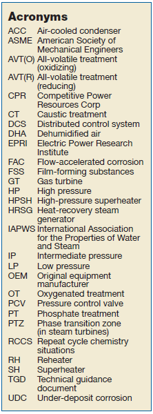
Dooley specializes in identifying and resolving damage and failure mechanisms in powerplants, and has global expertise in HRSG tube failure reduction/cycle-chemistry improvement, and FAC programs (see sidebar of acronyms).
Anderson, as principal of CPR, is focused on HRSGs and their related steam-plant auxiliaries in the combined cycle/cogeneration sector of the electric-power industry. Of particular note is his experience in identifying avoidable and damaging thermal transients in HRSGs and their cause/effect with operating procedures. His relationship with Dooley incorporates decades of powerplant analysis, design, and hands-on experience in both system mechanics and chemistry globally.
APWS and related organizations (EPRI, ASME, and several others) keep up with changes in powerplant applications. But all would be first to state that their work is based on the fundamentals and working experience of water chemistry, thermodynamics, fluid dynamics, heat transfer, two-phase flow and circulation, metallurgy, structural analysis, and design.
So, when these experts offer insights on trends we should listen, discuss, and learn.
Part 1: CYCLE CHEMISTRY
A decade ago, CCJ ONsite issued a report by Dooley and Anderson assessing trends in HRSG cycle-chemistry and thermal-transient performance, compiling information gathered from a variety of plants and locations. Their review noted that the frequency of damage and failures in the subject plants had remained almost the same for 20 years. Their latest and much more comprehensive study should leave no doubt about the previous results.
The authors remind us that materials of construction and their long-term reliability depend on internal surface protective oxides. As one primary example (feedwater sections up to about 570F), iron oxide is a passivating protective layer on a metal surface that acts against further corrosion.
Formation of these critical oxides relates directly to the cycle-chemistry treatments used in the condensate, feedwater, boiler/HRSG evaporator water, and steam.
The cycle-chemistry damage and failure mechanisms are all influenced by operating with less than optimum treatments, and doing so results in protective oxide breakdown.
Thus, in a powerplant setting, establishing the appropriate chemistry for the materials involved then exercising vigilance to detect any signs of chemistry upset are required.
The chemistry of the condensate and feedwater is critical to the overall reliability of HRSG plants. Good cycle chemistry is designed to prevent and/or reduce corrosion and deposits in the water/steam circuit, usually initiated and managed through a combination of techniques.
All-volatile treatment (AVT), applied to condensate and feedwater, represents the simplest form of chemical conditioning. The four standard variations are:
-
- AVT(R), all-volatile treatment (reducing).
- AVT(O), all-volatile treatment (oxidizing).
- OT, oxygenated treatment.
- FFS, film-forming substances.
Over time, AVT(O) has emerged as the preferred treatment for HRSGs in combined-cycle plants. For some units, adding solid alkalizing agents to drum/evaporator water might be needed to improve tolerance to impurities and reduce corrosion risks. Common agent methods are phosphate treatment (PT) and caustic treatment (CT).
Some rules of thumb. IAPWS and the authors of the “10-Year Review” tell us that there are now some proven Rules of Thumb, tested by time, location, and operating experience. These are valid for plants where steam and water contact only ferrous materials.
1. An oxidizing treatment—AVT(O) or OT—should be used to prevent single-phase FAC. AVT(R) should NOT be used. And here emerges one of the frustration points. “The global situation is improving, but AVT(R) is still used in more than 30% of units worldwide, reduced from about 70% in the early 1990s,” the report states. This, we are told, is a major reason single-phase FAC is still occurring.
2. An elevated pH with ammonia or an alkalizing amine is needed to control two-phase FAC. A pH of up to 9.8 is recommended.
3. Total iron corrosion products should be carefully monitored to target <2 ppb in the feedwater and <5 ppb in the drums. These levels are achievable if the optimum chemistry is used.
 FAC detection is critical. Corrosion products like to move. FAC, the authors and others have determined, can occur in the preheaters, economizers, and evaporators of HRSGs. Benign corrosion products released by FAC then move to the HP evaporator and deposit on the heat-transfer surfaces. These deposits, when thick enough, can then “act in the evaporators as initiating centers for some of the tube failure mechanisms.” If dangerously thick HP evaporator tube deposits are permitted to accumulate, they must be removed by expensive chemical cleaning to avoid tube failure mechanisms.
Cycle-chemistry adjustments are key to reducing or eliminating both single- and two-phase FAC, causes of significant and costly equipment failures. The “10-Year Review” stresses, “It is most important to identify the type of FAC correctly because the cycle-chemistry solution to arrest single-phase (use of oxidizing treatments) is quite different to that for two-phase (use of elevated pH up to 9.8).”
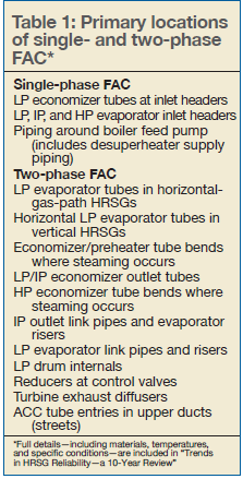
According to the report, most plants address single- and two-phase FAC at the same time from a chemistry application, which is incorrect. The first step is to recognize the primary FAC locations (Table 1). The second step is to find the evidence and distinguish between single- and two-phase FAC. “If these surface features are linked with the location of the FAC, then it should always be possible to identify the correct type of FAC occurring in the HRSG,” the report states.
RCCS. By looking at a large HRSG population over a substantial time period and diverse locations, the report’s authors can clearly determine repeat cycle-chemistry situations (RCCS) that should alert owner/operators to impending damage. In total, there are 10 RCCS associated with combined-cycle plants, and the most common are outlined below (but all should be studied in the published study):
Corrosion products. The authors tell us that correct monitoring of total iron (Fe) within the system should be a priority for any powerplant. Such analysis is key to optimizing a plant’s cycle chemistry, and for lowering the risks of FAC and under-deposit corrosion (UDC). Comprehensive assessments in the latest study uncovered findings such as:
-
- Corrosion product levels were not known. Even if monitored, there were often too few monitoring locations and/or inadequate sampling techniques. And, if samples were taken, analysis was often limited to the soluble part of total iron. Samples should be digested to determine total iron.
- If proper levels were known, they were too high.
 HP evaporators. Corrosion products found on the inside surfaces of HP evaporator tubing should alert owner/operators to corrosion and FAC in the sections of the cycle at lower pressure. Assessments revealed the following:
-
- Owner/operators had no knowledge of deposit levels, even in plants with severe FAC.
- If known, deposit levels were not linked with chemistry in the lower-pressure circuits or to the levels of transported total iron.
- HP evaporator samples from specific locations had not been taken for proper, accurate, and complete analysis.
- Some evaporators had been sampled and needed cleaning, but management had delayed or cancelled the activity.
- If accurate, deposit levels were known, they were too high.
Online instrumentation. IAPWS offers a detailed guidance document on instrumentation for both monitoring and controlling cycle chemistry in combined-cycle plants. However, site reviews found the following:
-
- Instrumentation as a percentage of IAPWS guidance, installed and operating, ranged from 0 to only 60%.
- Many plants used grab samples only.
- Instruments were improperly maintained or calibrated, or were simply out of service.
- Alarms for operators in control rooms were lacking or non-existent.
Air in-leakage. The common problem of air in-leakage (AIL) reduces both plant capacity and efficiency and makes cycle chemistry much more difficult to control. According to IAPWS, “AIL often contributes to subcooling of the condensate and to increased concentrations of dissolved oxygen and other contaminants in the condensate.”
Common sources of in-leakage are condensers, pumps and valves, and instrumentation penetrations, among many others. Detection and maintenance are critical. But detection program reviews showed a high level of site indifference.
Some owner/operators showed little awareness of potential impacts:
-
- At some locations, there were no detection teams or programs in place.
- AIL measurement methods were faulty, no vacuum test had been performed, or inert tracer (for example, helium) was not used.
- If air in-leakage was detected, correction was too often given low priority.
HP drum carryover. This repeat situation is of primary importance to protect the phase transition zone (PTZ) of the steam turbine if contaminants are allowed to enter the cycle. Also, “any condenser leakage will immediately elevate the HP drum and HP superheater chloride levels.”
Categories identified in the survey included:
-
- No carryover testing had been completed since commissioning.
- Plants were not aware of the simple process involved.
- Saturated-steam sampling equipment was non-existent or not operating.
Shutdown/layup protection. Lack of proper protection has led to serious pitting damage in HRSG drums and in steam turbines. Findings included the following:
-
- No equipment had been used for nitrogen blanketing and/or dehumidified air (DHA).
- Layup equipment was installed, but had not been maintained or operated properly.
- Owner/operators did not recognize potential risk to the phase transition zone in the low-pressure steam turbine.
- There was no awareness of potential benefits (or dangers) of using film-forming substances (FFS).
Challenging the status quo. The authors list this category as “perhaps the most important RCCS for damage prevention (arresting FAC and preventing UDC in power cycles).” Some examples:
-
- Reducin
 g agents still being used.
 - Unchanged system chemistry since commissioning.
- Guidelines incorrect or out of date.
- System pH low.
- Chemical addition points incorrect.
- Widespread failure to question the use of proprietary chemical additions (phosphate blends, amines, film-forming substances) or know the exact composition of the chemicals being added.
- Reducin
One interesting note from the report: “Equal results have been found by Dooley in assessments of over 120 conventional fossil plants.”
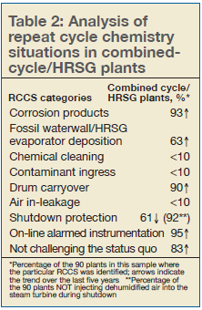
Things that can be addressed. Here is a telling summary statement from the authors: “For plant operators and chemists who want to be on the path to world-class performance, Table 2 provides the most important cycle-chemistry aspects which need to be addressed to ensure they avoid future cycle-chemistry-influenced damage or failure.”
The numbers in the table represent the percentage of plants examined by Dooley and Anderson where the particular RCCS was identified. Arrows indicate RCCS trends industry-wide over the last five years: improvement, no discernable change (no arrow), a step backwards.
The results tabulated illustrate why three major damage/failure concerns (FAC, UDC, and steam-turbine PTZ) continue to occur worldwide despite the excellent understanding of the mechanisms, the well-documented system locations, and the availability of comprehensive guidance available from IAPWS and others.
 New and existing plants. For new plant development, the best way to ensure proper chemistry is to incorporate the suite of IAPWS Technical Guidance Documents into the specification phase, proper chemistry thus becoming part of the plant’s status-quo policies and procedures. This also will help ensure alignment with the three guiding principles of oxidizing treatment, proper pH, and the achievable values of <2 and <5 ppm iron (feedwater and drums, respectively).
Once in operation, owner/operators should focus their attention to the repeat cycle chemistry situations, addressing each with a clear and complete action plan. Such attention should eliminate situations known to cause damage and failure.
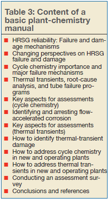
Perhaps most important, each facility should maintain a comprehensive Plant Chemistry Manual that includes the latest cycle-chemistry targets. A suggested table of contents is offered by Dooley and Anderson in their published 2019 study (Table 3).
Part 2: THERMAL TRANSIENTS
The first part of this report offered selected highlights on the damage and failure mechanisms resulting from improper attention to system water chemistry. Part 2, here, continues with a focus on damaging thermal transients. A thorough review of “Trends in HRSG Reliability—a 10-Year Review” will go deep into details, hands-on experience, insights, and assessment methodology. You can download the complete report here at no cost.
Thermal transient damage. In brief form, thermal-transient-influenced damage and failure categories and details are:
HRSG tube failures
-
- Thermal creep-fatigue in HP superheaters and reheaters at tube-to-header welds.
- Thermal fatigue in economizers at tube-to-header welds.
- Tube distortion in economizers, HP superheaters, and reheaters.
- Accelerated thermal aging (overheating) of HP superheater and reheater tubes downstream of duct burners.
- Water/acid-influenced corrosion in LP economizers (feed water inlet temperature).
Steam piping failures
-
- Thermal creep-fatigue in HP superheater and reheater attemperator pipe girth welds.
- Thermal quench cracking in HP superheater and reheater attemperator pipes, elbows, and tees.
- Transient and permanent thermal distortion (hogging and humping) downstream and upstream of attemperators.
- Thermal fatigue in HP superheater and reheater drain pipes.
- Thermal fatigue in girth welds downstream of HP and IP bypass desuperheaters.
- Ageing of pipe downstream of the HP bypass pressure control valve.
HP steam drum damage
-
- Corrosion fatigue at shell-to-downcomer and shell-to-nozzle welds.
Valve damage
-
- Erosion of HP bypass pressure control valve (PCV) seat and plug (from improper operation).
Background. Industry and study backgrounds are presented in Part 1. Regardless of OEM, some level of corrosion (both gas- and steam/water-side) and thermal degradation (creep and fatigue) will occur in HRSG pressure parts.
The report’s authors, Barry Dooley of Structural Integrity Associates Inc and Bob Anderson of Competitive Power Corp, tell us that “the key to reliable operation and long service life is limiting the rates of these damage mechanisms to those anticipated by the designer.”
When the first F-class HRSGs came into service (1990s), contractors, component manufacturers, and owner/operators did not recognize many of the thermal-fatigue damage issues that would or could surface. As one example, few recognized that condensate would form in the HPSH and RH during startup, and drains were not designed to be open during startup.
As another, the ASME Boiler and Pressure Vessel Code did not require performance of fatigue analysis during the design process. Most designers and owner/operators projected ongoing baseload operation.
Beginning in 1998, Anderson (then with Florida Power Corp) and others began studying the temperature impacts on HRSG tubes, pipes, and headers. Many of these findings are referenced in the new report and form the basis for today’s ongoing analyses and system operation reviews.
By 2009, retrofits had addressed some of the problems, including these:
-
- Redesigned attemperators, control valves, and control logic.
- Modifications to HPSH/RH modules to decrease rigidity.
- Modifications to HP/IP economizer headers.
- Replacing original drain pipes with larger pipe sizes.
- Bypassing elevated blowdown tanks at low pressures.
Since 2009, the authors have conducted surveys at an additional 45 combined cycle/HRSG plants throughout the world and have incorporated those findings in their 2019 report.
Operations. Thermal transients in HRSG components are unavoidable. Repeated transients, aggravated by both cycling and low-load operation, can lead to “incremental accumulation of invisible, irreversible fatigue damage in these components during each transient,” according to Anderson and colleagues. The degrees of damage, the assessments tell us, depend primarily on the following:
-
- Size of the thermal transient (both heating and cooling).
- Component design details.
- Material properties.
In turn, each component’s finite fatigue life “is dependent on the degree of fatigue accumulation during each cycle and the number of cycles experienced.” Damage is cumulative. Thus, most failures “are the result of larger and/or more frequent thermal transients than anticipated by the designer.”
Enter today’s environment of repeated cycling, low-load operation, and shutdown.
Can we see it coming? The authors’ experience indicates that most failures result from unidentified or unresolved operational issues, leading to these common occurrences (among others):
-
- Leaking of attemperator/desuperheater spray water.
- Attemperator overspray.
- Insufficient draining of HPSH/RH condensate during startup.
- Inappropriate operation of HP and hot-reheat bypass systems.
- Economizer inlet quench.
New results? Not really. As the authors state, “Unfortunately, many of the avoidable causes of damaging thermal transients identified in 2009 continue to be common findings in these later surveys.” Surveys show persistence of some of the design weaknesses and repetition of non-optimum operating procedures, such as:
-
- Insufficient straight steam-pipe length downstream of attemperator spray nozzles.
- Lack of or improper protective control logic for attemperators and valves.
- Operating procedures that misuse the interstage attemperators during startup and shutdown.
- Attemperator overspray.
- Permitting operators to manipulate attemperator setpoints or manually control spray valves.
- HPSH and RH drain system operating procedures that fail to completely drain during startup.
- Aggressive increase or decrease in HP drum pressure.
A new phenomenon appeared in the HP steam-turbine bypass circuit: Erosion of the pressure control valve cage, disc, and seat by wet steam and water.
How to identify. The authors go into detail on identifying “the most common underlying causes of failures driven by avoidable thermal transients.” Emphasis is on the word “avoidable.”
Attemperator spray water leaking past the block and control valve remains common (82% of 54 plants evaluated). The authors note that small to moderate leaks (seen on DCS data plots) may be viewed as insignificant by operators, but “even a small leakage rate into hot steam pipes during periods of zero to low steam flow causes cracking (1) of thermal liners, (2) at the inner surface of steam pipes, and (3) in girth welds.” Also, temperature differences between bottom and top of pipes can cause distortions that impact even the pipe support system. Water can become trapped in lower areas.
Many systems, the authors say, use master control/martyr block spray valve logic. With many open/close cycles on the block valve, the seat is damaged and the control valve’s seating surface is now exposed to high differential pressure. This arrangement is said to be a major cause of leakage.
Overspray means that not all spray water can be evaporated before the first downstream elbow or tee fitting. Best practice is a minimum 50 deg F superheat at the attemperator outlet. Design issues include insufficient steam pipe length, inferior quality spray nozzles, and improper HPSH/RH heating surface arrangement. Other factors are inferior control logic and operator intervention.
Inappropriate attemperator operation. When steam flow is low or zero and pipes are hot an immediate tube failure is possible because of ductile overload. More frequent damage is caused by (1) spray operation too early in startup or too late in shutdown, (2) manual manipulation of set points, and (3) inappropriately using interstage spray to match outlet steam attemperators for startup of the steam turbine. One suggestion for plants equipped with GE gas turbines is exhaust-temperature matching.
Inadequate draining during startup. Condensate must be drained before initiation of steam flow in the HPSH and RH. During all types of startup, water will migrate and quench some of the tubes if not completely drained. During hot starts, cooler water in the HPSH and lower piping will move upward and enter the hot upper headers, manifolds, and steam piping.
Aggressive HP drum pressure ramp rates. Dooley and Anderson say that “repeatedly cycling the drum near or beyond the maximum permissible ramp rate is likely to result in cracking of the protective magnetite layer, followed by corrosion fatigue cracking of the underlying steel.” Note that if weld repair becomes necessary, both welding and post-weld heat treatment are expensive and time consuming.
Forced cooling. Many owner/operators force-cool the GT and HRSG after shutdown to expedite maintenance activities. “If not carefully managed, forced cooling can impose extreme thermal transients on the HP drum, HPSH/RH headers and piping, and main steam/hot reheat piping,” the authors warn.
HP bypass-valve erosion. Abnormal seat, plug, and cage erosion in bypass pressure control valves has become common regardless of valve manufacturer, “caused by passing wet steam and/or water through the PCV. As damage progresses, superheated steam can leak through and overheat the downstream carbon steel pipe.”
HRSG designers have long suggested that cooling steam flow be initiated in the HPSH/RH “as soon as possible.” The surveys show an increase in control logic accomplishing this by immediately opening the PCV at GT light off during startup, or before the main steam pipe upstream of the PCV is properly heated. The authors suggest that “as soon as possible” should not require unacceptable damage to the bypass system. Few plants are equipped with permanent instrumentation to measure steam temperature at the PCV.
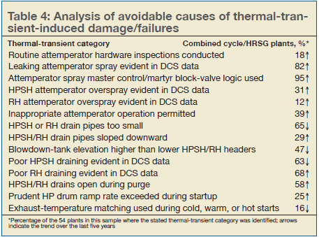
Ranking the key causes. The authors’ original paper, issued in 2009, ranked 55 potential causes of damaging thermal transients. Many have since been addressed through improvements in equipment design and operating procedures. But serious causes remain, and Table 4 presents the most important by category. As for Table 2, the numbers represent the percentage of plants and the arrows indicate trends.
Avoidance. The authors clearly and comprehensively address strategies for avoiding damage in both new and operating plants. These strategies are summarized below.
Leaking spray water. Dooley and Anderson suggest a reverse logic for valve protection, to a master block/martyr control valve logic and an attemperator system release permissive that results in the block valve opening only during startup just prior to first attemperator use, and closing only prior to GT shutdown.
Overspray and inappropriate operation. Overspray strategies include equipment and maintenance upgrades, properly designed and tuned cascade control systems, prohibiting operators from manually adjusting setpoints or operating spray valves, and ensuring an overspray protection feature on system controls to maintain 50 deg F of superheat at the attemperator outlet.
Failure to adequately drain. Key steps in effective drain modifications include calculating the rate of condensate formation, and determining the minimum drain pipe sizes and arrangements. The section on automatic drain control in the 2019 report lists features that should be included in the modifications—such as slope, blowdown tank location, use of thermocouples, installation of an effective automatic drain valve system, and compliance with personnel safety and/or environmental protection practices. Proper procedure results are noted.
Aggressive drum-pressure ramp rates. Legacy units may not have been provided with suitable ramp rates. The authors note that “it may be necessary to hold GT load at a low value for some period during cold/warm startup to avoid exceeding safe HP-drum ramp rate limits. HP bypass and HP sky vent availability and capacity are key factors in complying with drum ramp rate limits later in the startup.”
HP bypass valve erosion. Although not a thermal transient, this common problem is discussed and several suggestions listed including: “delaying opening of the HP bypass PCV until steam temperatures upstream and downstream of the HP bypass branch tee have increased above saturation temperature during startup.”