The 7EA Users Group has joined Power Users, the umbrella organization for managing and coordinating the technical programs for many of the electric power industry’s leading user groups—including 7F, Combined Cycle, Steam Turbine, Generator, and Power Plant Controls. Sheila Vashi (sheila.vashi@sv-events.net) of SV Events will coordinate the 2020 conference and vendor fair at the J W Marriott Houston Galleria, October 19-22.
2020 7EA Users Group meeting in Houston, October 19-22
J W Marriott, Houston Galleria
Houston, Tex · October 19-22
Steering Committee
Dale Anderson, East Kentucky Power Co-op
Tracy Dreymala, EthosEnergy, San Jacinto Peakers
Guy LeBlanc, First Energy Group
Tony Ostlund, Puget Sound Energy
Mike Vonallmen, Clarksdale Public Utilities
Lane Watson, FM Global
The 7EA gas turbine’s many attributes—including generally high reliability and availability, and good efficiency in a wide range of applications on a variety of fuels—help make it the most popular mid-size (nominal 85 MW) industrial gas turbine. There are said to be about 1200 of these machines in service.
Annual conferences of the 7EA Users Group attract upwards of a hundred attendees, representing owner/operators from across the globe, to share experiences. Inspections and overhauls typically are a focal point of interactive discussions among users. Virtually everyone in the room wants to know what issues to be aware of, where they are likely to occur, what the indications look like, how frequently their engines should be inspected, etc.
Inspection findings. At the 2019 meeting, last fall in Louisville, the editors spoke to Mike Hoogsteden, director of field services for Advanced Turbine Support LLC, which inspects scores of these machines annually, to learn how users can make their outages more productive and minimize the possibility of missing something that could contribute to a forced outage.
A good place to start, he said, is to review the OEM’s Technical Information Letters (TILs) pertaining to the 7EA, take notes, and bring your questions to the next user-group meeting. Your colleagues and participating suppliers are the best source of advice on what’s important and what’s not, Hoogsteden added. The knowledge gained will help you plan the optimal outage for your gas turbines.
Five TILs he suggested users become intimately familiar with are these:
1884, “7EA R1/S1 Inspection Recommendations,” which addresses the need to inspect R1 and S1 airfoils for possible damage caused by clashing—the unwanted contact between S1 stator-vane tips and R1 rotor-blade roots during operation.
1980, “7EA S1 Suction Side Inspection Recommendations,” which advises users to inspect for crack indications on S1 vanes made of type-403 stainless-steel, regardless of whether clashing damage is in evidence on S1 and R1 airfoils.
1854, “Compressor Rotor Stages 2 and 3 Tip Loss,” which suggests blending and tipping to mitigate the impact on availability and reliability of R2 and/or R3 tip loss. This TIL supplements information provided by the OEM in the O&M manual provided with the engine.
1562-R1, “Heavy-Duty Gas Turbine Shim Migration and Loss,” which informs users on the need to monitor the condition of compressor shims and corrective actions available to mitigate the risks of migrating shims.
1744, “S17, EGV1, and EGV2 Stator-Ring Rail and CDC Hook Fit Wear Inspection,” provides guidance on the repair of dovetail wear and suggests hardware and software enhancements available to mitigate the potential risk caused by operating conditions that promote such wear.
There are many more TILs that demand your attention, to be sure. One is 1090-2R1, “Compressor R17 Blade Movement.”
Blending to Stage 11. When compressor inspections point to the need for blending to remove stress concentrations or cracks that could contribute to the liberation of a blade or pieces of one, Hoogsteden recommends it be done in-situ. This saves time and cost by limiting the extent of unit disassembly required to make the repair. He said that Advanced Turbine Support is now able to perform in-situ blending on 7EA compressor rotors from the inlet guide vanes to Stage 11.
Summaries of several other presentations made last year follow.
Emerson’s Patrick Nolan, well respected by GE 7EA users for his knowledge of the gas turbine and its control, focused on fast starting and fast loading of a simple-cycle engine to take advantage of market opportunities created by recent industry changes. While starting in 10 minutes or less and/or loading at up to 30 MW/min can create new revenue opportunities, he noted, the lifetimes of hot parts would be reduced. There is no free lunch.
Nolan’s charts compared a typical 12-min normal start to a fast start of about 8 min possible with control-system modifications. Stepwise, the fast start he described would look something like this:
-
- Start to purge speed, less than 0.5 min.
- Purge, 1.5 min.
- Ignition and warmup to reach 25% speed, less than 0.5 min.
- Acceleration from 25% to 100% of rated full load, about 5 min.
- Synchronization, about 0.5 min.
Taking advantage of NFPA-85 purge credits on shutdown, which requires additional, but affordable hardware, eliminates the need for a startup purge, saving significant time when trying to satisfy market demands.
Logic to test field devices when the turbine is in standby and receive positive feedback that the entire control system is functional also is required. The owner/operator is responsible for evaluating the safety associated with this activity and when to perform testing, given any operational constraints.
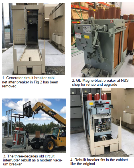
Old GCB made new. There’s often no substitute for the experience gained at user-group meetings. Consider the case history, presented by a West Coast utility at the 2019 7EA conference in Louisville, on the rehab and upgrade of a 35-year-old main generator circuit breaker (GCB) that simply wore out after three decades of dependable service.
You probably could count on one hand the number of plant personnel who had seen the GCB out of its cabinet since COD. So why would you expect someone on the current staff to know anything about this piece of equipment and how to troubleshoot it, and then what to do when a subject matter expert said it should be replaced?
There almost always are options. In this case, you could buy new—the easiest, and most expensive, option—or you could rehab and upgrade the superannuated breaker and save, perhaps, 75%. A pitfall of buying new is that it likely would require a new cabinet, new foundation, etc. Old-made-new allows use of existing infrastructure and you just pay for the breaker.
Here’s what was involved in this project:
1. Pull the old 15-kV GE Magne-blast circuit breaker from the cabinet (Fig 1) and ship to National Breaker Services (NBS) for rehab and upgrade (Fig 2).
2. Rebuild as a modern vacuum breaker and return to the plant (Fig 3).
3. Roll the NBS Citadel-4000 breaker into the cabinet without having to make any changes to the existing infrastructure (Fig 4).

Inlet and exhaust systems, when neglected, are gas-turbine performance thieves. Jeff Cozeby and Laqunnia Lawson identified for 7EA users some of the problems Schock Manufacturing finds when performing inspections on, and making repairs to, these systems. The presenters piqued the interest of conference attendees by offering free inspections through the company’s website.
Cozeby and Lawson began by pointing to corrosion and dirty-air bypass as major contributors to problems found with inlet filters and the inlet duct system. They typically trace the source of these problems to poor design and lack of maintenance and housekeeping. Telltale signs of trouble include corrosion, loose internal parts, leaking gaskets, failed expansion-joint belts, loss of fill in silencer panels, among other things.
The heart of the exhaust ducting, the pair continued, is the internal liner and insulation system. When not properly designed and/or maintained, or repaired improperly, failures occur. Among the things Schock personnel look for during an inspection are casing hot spots (paint peeling or discolored), sheared or broken studs, exposed insulation, liner cracks, wear and tear of expansion joints, gasket failures at access doors, and loss of fill in silencer panels.
The speakers showed more than three-dozen photos to illustrate their points, providing attendees a valuable library of findings to make operator rounds more meaningful. The key takeaway was for staff to catch problems early when repairs usually are easier and less expensive to make.
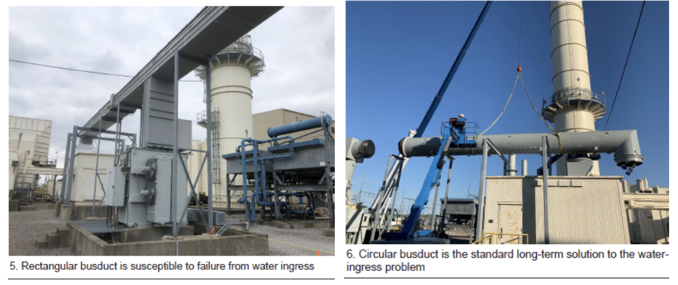
Busduct replacement. A utility user provided an overview of a project involving replacement of rectangular non-seg busduct with circular non-seg busduct at two generating units in the Midwest. The former was susceptible to failure from water ingress (Fig 5); water would pool on the top of the busduct and leak inside at joints. Over the years, electrical shorts became more frequent. First corrective action was to replace internal duct insulators with ceramic ones. This worked, but only for a while.

The speaker said circular non-seg busduct had evolved as the industry’s standard long-term solution to the water-ingress problem (Fig 6). He offered the following advantages of circular busduct over the rectangular configuration:
-
- Geometry allows it to shed water quickly.
- All flanges are welded, not bolted.
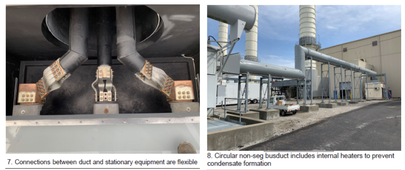
- The connections between the duct and stationary items (generator circuit breaker, step-up transformer, and generator) are flexible, thereby reducing vibration stress points (Fig 7).
- Aluminum housing resists rust and corrosion.
- Reuse of the existing busduct structures was possible with only new mounting hardware.

Crown Electric was selected to manufacture and install the circular bus, which included internal heaters to prevent condensate formation (Fig 8). As to schedule, the speaker said equipment was delivered to the site about three months after the purchase order was issued. Demolition of the rectangular busduct and installation and commissioning of the circular replacement took two weeks.

