![]() The first meeting of the Australasian Boiler and HRSG Users Group (ABHUG), held last fall (2019) in Brisbane, Australia, followed 11 annual meetings of AHUG (Australasian HRSG Users Group). The added B is for boilers. Content now includes conventional fossil-plant technologies and issues closely related to those involving heat-recovery steam generators in combined-cycle and cogeneration systems.
The first meeting of the Australasian Boiler and HRSG Users Group (ABHUG), held last fall (2019) in Brisbane, Australia, followed 11 annual meetings of AHUG (Australasian HRSG Users Group). The added B is for boilers. Content now includes conventional fossil-plant technologies and issues closely related to those involving heat-recovery steam generators in combined-cycle and cogeneration systems.
ABHUG is an interactive forum for the discussion of new information and technologies related to HRSGs and boilers—including case studies of plant issues and solutions. The event is supported by the International Association for the Properties of Water and Steam (IAPWS) and its national committees in Australia and New Zealand.
The 2019 agenda featured 21 presentations plus a comprehensive workshop on welding, which included segments on ligament cracking in superheater headers, cold repair of Grade 91 materials, and modifications to HRSG ducting.
Updates also were provided for system chemistry, instrumentation and FAC, and thermal transient issues for attemperators, condensate return and superheater/reheater drain management, and bypass operation.
One shared HRSG/boiler issue is layup and offline protection, increasingly common to all operating systems that make way for the growth of renewables. Improper shutdown and layup procedures are now a standard topic at these industry events.
What follows is an insight into some of the shared challenges.
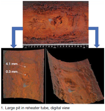
Pitting corrosion at Tarong. The 1400-MW Tarong Power Station in Queensland was commissioned in the 1980s with four subcritical coal-fired boilers, each rated at 350 MW. The primary reheater is located in the back pass, composed of two sections with horizontal tube elements—126 total elements across each boiler’s width. Design steam conditions at the headers are 935F at 765 psig (610 psig operating).
In 2012, owner/operator Stanwell Corp announced plans to shut down two units for two years because of reduced demand and low wholesale electricity prices. When the cost of natural gas rose in 2014, Stanwell returned the units to service.
Following a Unit 3 major outage in 2018, four reheater tubes across different elements experienced primary failures. Two months later, another two tubes across different elements experienced similar failures (Fig 1).
An EPRI roadmap was used to identify, evaluate, and solve the boiler-tube failure issue—EPRI Technical Report 3002010388, “Boiler and heat recovery steam generator tube failures: theory and practice.”
Stanwell adopted the process described in the EPRI document to determine the following:
1. Primary failure location.
2. Primary failure mechanism.
3. Primary failure root cause.
4. Factors contributing to the primary failure mechanism.
Both visual and tube-removal analyses revealed the key factors and mechanism:
-
- Corrosion only in the bottom half of the tube.
- Partial or complete through-wall pitting corrosion on welds and randomly on tube parent material.
- Pit sites open or filled with reddish or reddish-brown corrosion products.
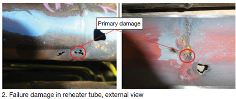
In this case, all pit sites were located in the center sections of horizontal tubes (Fig 2). There was no external erosion, apart from steam erosion, attributed to the primary failures. Stanwell’s conclusion: Pitting corrosion attributed to inadequate layup was the primary failure mechanism.
Investigations included metallography, water sources and system chemistry, shutdown procedures, reheat spray operations, and pressure excursions.
Stanwell’s G Wang stated the primary failure root cause as “condensate formed during shutdown. The accumulation of condensate at the bottom of the tubes with oxygen being subsequently introduced during the shutdown provides a stagnant oxygenated-water environment for pitting initiation and development.”
Wang also reviewed relevant contributing factors:
-
- History of shutdowns, durations, and long-term preservation practices.
- Chemical excursions (condenser leaks, for example).
- Corrosion at welds caused by weld/tube galvanic attack.
- Sagging at center of horizontal tube elements.
- Pressure excursions.
- Lack of protection during washdown after tube failure events.
Stanwell’s long-term strategy includes repair/replace option reviews, enhanced inspection methods, and a direct action for shutdown of “drying the tubes before condensate formation and maintaining RH below 35%.”
Wang then listed specific future inspection methods:
Welds. Cobra PAUT/ToFD (ultrasonic phased array and time-of-flight diffraction) ultrasonic.
Tube parent material. EMAT and FMC/TFM (electromagnetic-acoustic transducer and full-matrix capture/total focusing method).
During discussions, Structural Integrity’s Barry Dooley stressed the benefits of “sharing issues across combined-cycle and conventional fossil plants. Corrosion can be initiated during inadequate layup. This and other presentations illustrate just how severe pitting damage can be for both combined cycle and conventional units.”
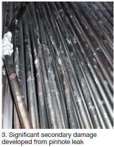 Kogan Creek Power Station (CS Energy Australia) is a 750-MW supercritical coal-fired unit in Queensland, commissioned in 2007. In 2018, a tube leak occurred in the horizontal reheater section of the boiler, causing significant secondary damage and an 11-day forced outage. Fifteen tubes were replaced (Fig 3). The primary failure was a pinhole leak that developed near the middle of the horizontal run, at the bottom of the tube. The failure mechanism was identified as pitting corrosion.
Galvanic corrosion caused by moisture and oxygen led to rapid pitting. CS Energy’s Luke Smith explained that “the base of the pit, low in oxygen compared to the wet metal surface, became anodic. This occurred during shutdown when steam was allowed to condense (not during operation). In this particular case, a low level of sulfate also was present.”
In 2019, the entire reheater was replaced (three banks of 196 elements), extending an outage from 56 to 77 days.
The long-term prevention objective is to replace dry steam with dry air (dry storage). Smith explained that “once the reheater has had about five changes of volume, the HP bypass is opened to allow air to flow to the superheaters. The flow of dry air will be maintained for the duration of the outage if possible. We aim for an RH below 30%.”
This was followed by participant discussion on use of dehumidified air (DHA) for systems including reheaters and steam turbines. Dooley again offered input: “Unfortunately,” he said, “the application of DHA is usually added after the damage has occurred, instead of proactively beforehand.”
AGL program. Stewart Mann, responsible for asset integrity at AGL Energy Ltd, discussed the corporate-wide approach to boiler-tube failures at both gas- and coal-fired steam turbine units.
The AGL tube-failure reduction program records each failure mechanism and root cause, the specifics of each repair, and all planned actions.
The approach discussion raised many logical but often bypassed steps needed for a complete analysis program. First, the AGL program is based on the model in EPRI Report 1013098, “Integrated boiler tube failure reduction/cycle chemistry improvement program (2006).” Second, it is produced as a fleet-wide AGL standard. Third, it is now integrated with AGL’s cycle-chemistry standard.”
The goal is to apply risk-based systems to minimize repeat failures, reduce failures from new mechanisms, and decrease the number of failures at new locations for known mechanisms. As Mann stated, “Unless we have recently changed how we are operating, credible inspection and analysis should enable us to confirm whether a potential mechanism is an issue at our plants.”
Data gathering includes failure mode and mechanism, root cause, extent of damage to the tube with the primary failure, tubing in the vicinity of the primary failure (secondary damage), and the surface areas along the leaking tube.
“AGL is careful to preserve removed tubes for metallurgical examination, and to always consider possible removal of additional samples,” added Mann. Also, every repair has strict QA provisions for:
-
- Welder certification.
- Inspector certification.
- Welding procedures.
- Welding materials.
- Selection of tube materials.
“All of this,” he continued, “requires good collaboration among trading, operations, and engineering.”
Each ALG site now has a dedicated boiler-tube failure-reduction program team that includes:
-
- Site boiler engineer (lead).
- In-service inspector.
- Principal engineers from the company’s technical services group.
- Operations input.
- Maintenance input.
- Complete failure and inspection history reviews.
- Development of inspection strategy and action plans.
“All reports are finalized, distributed, and accessible to everyone,” he said.
Mann offered an interesting concluding challenge: “Play devil’s advocate, and be prepared to question any prevailing norms.”
A common tube-failure approach. Pitting issues from improper shutdown protection can affect both the HRSG and the steam turbine, as discussed in the recently released report “Trends in HRSG Reliability: A 10-Year Review,” by Barry Dooley and Bob Anderson of Florida-based Competitive Power Resources.
In that report, the authors discuss the importance of root-cause analysis and HRSG tube-failure (HTF) programs. They caution that a tube failure often is assumed to be a bad weld, but warn that if tube removal and analysis are not performed the problems will likely continue.
This review continues: “In many cases the actual root cause may be due to a cycle chemistry deficiency, design feature, or operating practice that has repeatedly inflicted corrosion, corrosion fatigue, or thermal-mechanical fatigue damage in the failed tube and its neighbors.”
It is indeed complex. “The only way to ensure that the corrective actions are taken and will prevent a tube failure from recurring is to remove the initial failure site, have the actual failure mechanism identified via a metallurgical laboratory analysis, then determine the root cause of the failure.”
The tube failure discussions at ABHUG were examples of effective root-cause analysis.

Also common: chromium risk. Chromium is a common alloy element in stainless steels and high-chromium-containing materials in steam turbines, steam turbines, boilers, and HRSGs. It is a transition element (metal) with multiple oxidation states.
 Chromium III is essential for human health; Chromium VI (hexavalent chromium) is extremely toxic. Chromium VI is also easily managed with standard industrial hygiene and personal protection strategies applied, combined with neutralization where needed.
Risks associated with welding of high chromium materials are well understood in the industry, as are possible hazards during some chemical cleaning procedures.
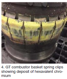
Recently, however, hexavalent chromium has been identified on gas-turbine hot-gas-path components (Fig 4), steam-turbine hot external components (bolts), and on the external surfaces of hot HRSG/boiler piping.
For gas and steam turbines, there’s a link to calcium-containing anti-seize pastes often used on hot components.
The yellowish appearance can be misinterpreted as sulfur deposits from the fuel. “Bright yellow HRSG gas-side deposits should be considered a major warning sign, and treated with significant caution,” cautioned David Addison, principal, Thermal Chemistry Ltd (New Zealand).
Although understood and manageable, this alert involved one particular slide labeled “unconfirmed risk areas”:
Upper and lower crawl spaces with:
-
- High-chromium pipework.
- High-chromium liner places.
- Oxygen atmospheres.
- High temperatures.
- Insulation containing calcium oxide.
- Potential for rain water ingress that allows for calcium leaching.
For HRSGs:
-
- Superheater/evaporator upper and lower crawl spaces.
- GT exhaust ductwork—mainly on the insulation side of plates.