Ventanilla Combined Cycle Power Plant
Owned and operated by ENEL Generacíon Perú
427 MW, 2 × 1 SGT6-4000F-powered dual-fuel powerplant, located in Callao, Perú
Plant manager: Dany Alcantara
Plant background. Endesa SA, Spain’s largest electric utility, won a tender in December 1995 to take control of Empresa de Generación Termoeléctrica de Ventanilla (Etevensa), the genco operating the Ventanilla thermal plant in Perú’s Callao Province, Lima Region. Etevensa had been spun off from Electroperu SA.
Endesa was the lead company in Consorcio Generalima, which also included two Peruvian companies. According to Christopher Bergesen, a Maryland-based consultant with deep knowledge of the global electric power business, the consortium bid $US120 million and agreed to modernize the plant.
The plant was upgraded in 1997 when the OEM of record supplied and installed a pair of 170-MW gas turbines, replacing the 110-MW 501D5 engines installed in 1993.
Endesa took full control of Etevensa in August 2003 and the following year converted Ventanilla to combined-cycle operation by adding a supplementary-fired HRSG downstream of each GT and a 184-MW steam turbine.
In September 2004, Ventanilla, now owned and operated by Endesa successor company Enel Generación Perú, began burning Peruvian gas and producing power for distribution via the national grid. In January 2021, Enel commissioned a 14.6-MW battery energy storage system—Perú’s first—using lithium-ion technology.
 Challenge. Prevent the recurrence of a transformer forced outage suffered by Ventanilla a few years ago when an HV bushing failed (Fig 1).
Solution investigated was the installation of an online monitoring system capable of detecting changes in critical operating data that might suggest an impending failure. The daily cost of a transformer outage at Ventanilla is about $100,000.
Investigations by plant personnel pointed to Camlin Energy’s Totus system, which is said to monitor all key components of the transformer, providing a picture of transformer health. It integrates dissolved gas analysis (DGA), partial discharge (PD), bushing monitoring (BM), through fault currents (a/k/a short-circuit currents), and transformer analytics into a single system.
The following instrumentation was installed on transformers serving the gas turbines: bushing sensor (Fig 2), load current monitor, communications mod bus TCP/IP, temperature monitor, oil leak detector, DGA, PD. Gases dissolved in the transformer oil, both analyzed and trended are hydrogen, ethylene, acetylene, CO₂, CO, ethane, methane, moisture, oxygen.
PD monitoring of transformer windings identifies amplitude, repetition rate, and PD persistence—the last to avoid a false alarm and provide reliable information. A PD-status level (scale of 1 to 10) is determined using amplitude and repetition rate.
Bushing health is tracked using tan delta and capacitance data. Leakage current from each bushing is monitored and variations in current amplitude and angle between adjacent phases calculated.
Recall that tan delta test results help gauge the condition of transformer insulation and determine how close it may be to a fault condition. There are two ways to evaluate insulation health during a tan delta test, according to information provided by Altanova, a Doble company:
- The first is to compare current results to those from previous tests, thereby determining the impact of aging on deterioration.
- The second is to determine directly insulation condition using the tan delta value. If the insulation is perfect, the loss factor will be about the same for the range of test voltages. But if the insulation is less than perfect, the tan delta value will increase as the test voltage increases.
Results. Since Ventanilla’s online monitoring program was implemented, there has not been a forced outage attributed to a transformer failure. Plus, plant personnel are more aware of the positive impact their vigilance can have on operating costs, as well as the safety benefits of avoiding a fire or explosion caused by a short circuit.
Enel project participants:
Gustavo Rodriguez, electrical specialist and project manager
Fernando Sarmiento, electrical supervisor
Eduardo Salinas, electrical supervisor
Ventanilla 2023 Best Practices
- Online monitoring alerts to transformer issues, protecting against a forced outage at Ventanilla
- HRSG deep cleaning with dry ice pellets at high pressure meets Ventanilla’s expectations
- Cooling-tower upgrade increases electric generation at Ventanilla
- Tighter control of circ-water chemistry improves economics, safety at Ventanilla

Ventanilla Combined Cycle Power Plant
Owned and operated by ENEL Generacíon Perú
427 MW, 2 × 1 SGT6-4000F-powered dual-fuel powerplant, located in Callao, Perú
Plant manager: Dany Alcantara
Plant background. Endesa SA, Spain’s largest electric utility, won a tender in December 1995 to take control of Empresa de Generación Termoeléctrica de Ventanilla (Etevensa), the genco operating the Ventanilla thermal plant in Perú’s Callao Province, Lima Region. Etevensa had been spun off from Electroperu SA.
Endesa was the lead company in Consorcio Generalima, which also included two Peruvian companies. According to Christopher Bergesen, a Maryland-based consultant with deep knowledge of the global electric power business, the consortium bid $US120 million and agreed to modernize the plant.
The plant was upgraded in 1997 when the OEM of record supplied and installed a pair of 170-MW gas turbines, replacing the 110-MW 501D5 engines installed in 1993.
Endesa took full control of Etevensa in August 2003 and the following year converted Ventanilla to combined-cycle operation by adding a supplementary-fired HRSG downstream of each GT and a 184-MW steam turbine.
In September 2004, Ventanilla, now owned and operated by Endesa successor company Enel Generación Perú, began burning Peruvian gas and producing power for distribution via the national grid. In January 2021, Enel commissioned a 14.6-MW battery energy storage system—Perú’s first—using lithium-ion technology.
Challenge. Restore HRSG performance while assuring the highest level of boiler reliability and availability going forward. During HRSG operation, deposits build up on heat-transfer surfaces and impede heat transfer (Fig 3). The corrosion products, ammonia salts, sulfur, and foulants—such as particles of insulation—trapped between tube fins should be removed periodically (Fig 4).
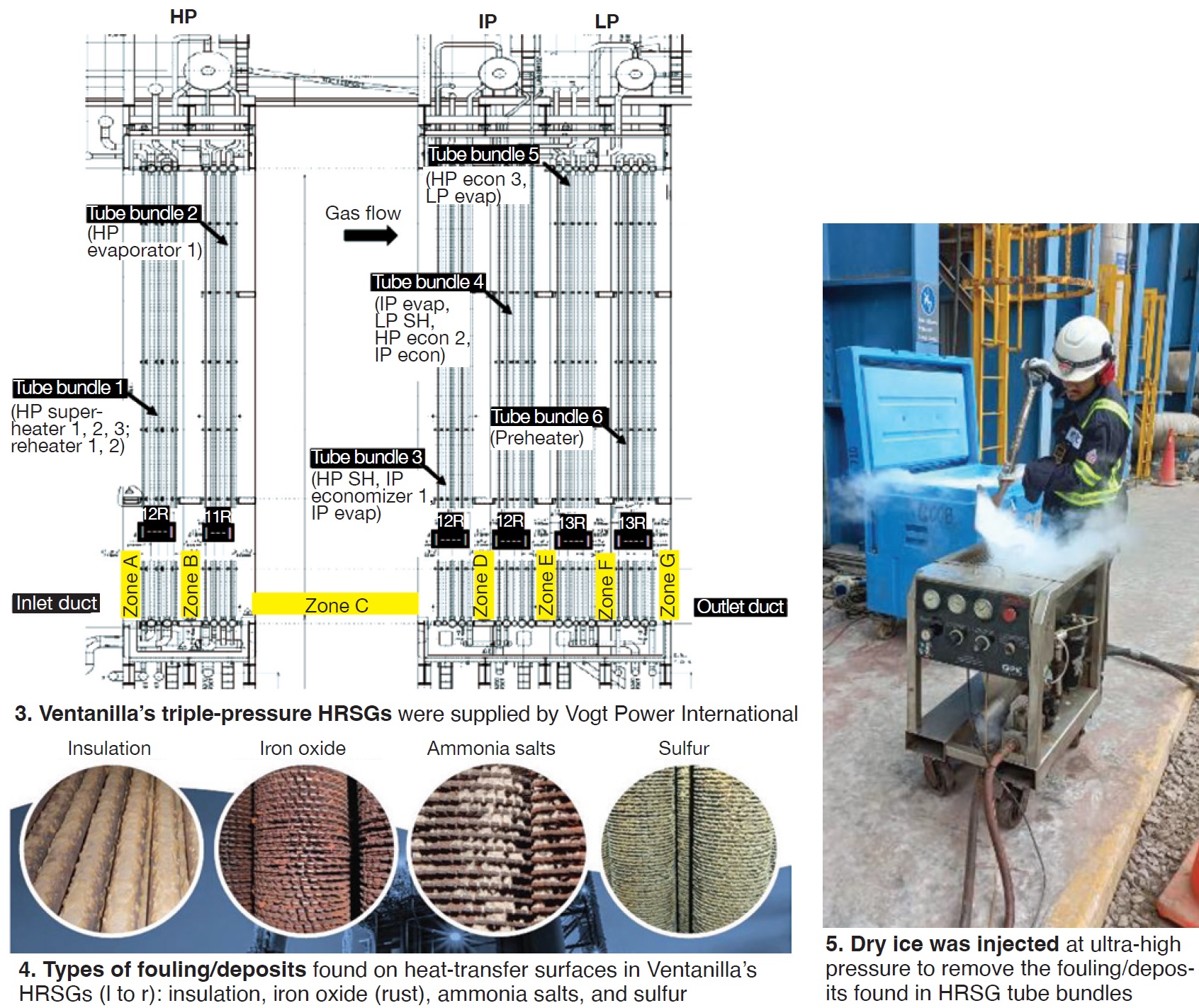
Solution. Plant personnel determined that a commercially available service for deep cleaning tube bundles using dry-ice pellets at high pressure (Fig 5) would remove about 95% of the performance-robbing deposits, thereby improving HRSG thermal efficiency, reducing gas-path backpressure, and increasing plant output. Cleaning also increases tube life and slows the corrosion processes conducive to tube failure.
Cleaning focused on the intermediate- and low-pressure circuits where the buildup of deposits was greatest. Scaffolding was erected in those sections in accordance with the following plan (refer back to Fig 3):
- Downstream face of tube bundle 6.
- Between tube bundles 5 and 6.
- Between tube bundles 4 and 5.
- Between tube bundles 3 and 4.
- Upstream face of bundle 3.
Cleaning then proceeded thusly:
- In the direction downstream of tube bundle 6 (so-called face 1 in the cleaning sequence).
- Direction upstream of tube bundle 6 (face 2).
- Downstream of tube bundle 5 (face 3).
- Upstream of tube bundle 5 (face 4).
- Downstream of tube bundle 4 (face 5).
- Upstream of tube bundle 4 (face 6).
- Downstream of tube bundle 3 (face 7).
- Upstream of tube bundle 3 (face 8).
Results for HRSG 1. The increase in power production for GT 1 was nearly 1 MW, for the steam turbine 0.5 MW. The annual economic benefit: $230,000 for increased production, plus $62,000 for increased capacity payments. Also noteworthy:
- Backpressure reduction of 5%, which contributed to the economic benefit.
- Increased HRSG life attributed to the slowdown in corrosive processes that could cause tube failures.
Enel project participants:
Ivan Jimenez, mechanical specialist and project manager
Sandro Garcia, responsible person for operational optimization
Jose Soto, operational optimization specialist
Richard Mejia, safety supervisor
Marco Rivera, responsible person for plant maintenance
Ventanilla 2023 Best Practices
- Online monitoring alerts to transformer issues, protecting against a forced outage at Ventanilla
- HRSG deep cleaning with dry ice pellets at high pressure meets Ventanilla’s expectations
- Cooling-tower upgrade increases electric generation at Ventanilla
- Tighter control of circ-water chemistry improves economics, safety at Ventanilla

Ventanilla Combined Cycle Power Plant
Owned and operated by ENEL Generacíon Perú
427 MW, 2 × 1 SGT6-4000F-powered dual-fuel powerplant, located in Callao, Perú
Plant manager: Dany Alcantara
Plant background. Endesa SA, Spain’s largest electric utility, won a tender in December 1995 to take control of Empresa de Generación Termoeléctrica de Ventanilla (Etevensa), the genco operating the Ventanilla thermal plant in Perú’s Callao Province, Lima Region. Etevensa had been spun off from Electroperu SA.
Endesa was the lead company in Consorcio Generalima, which also included two Peruvian companies. According to Christopher Bergesen, a Maryland-based consultant with deep knowledge of the global electric power business, the consortium bid $US120 million and agreed to modernize the plant.
The plant was upgraded in 1997 when the OEM of record supplied and installed a pair of 170-MW gas turbines, replacing the 110-MW 501D5 engines installed in 1993.
Endesa took full control of Etevensa in August 2003 and the following year converted Ventanilla to combined-cycle operation by adding a supplementary-fired HRSG downstream of each GT and a 184-MW steam turbine.
In September 2004, Ventanilla, now owned and operated by Endesa successor company Enel Generación Perú, began burning Peruvian gas and producing power for distribution via the national grid. In January 2021, Enel commissioned a 14.6-MW battery energy storage system—Perú’s first—using lithium-ion technology.
Challenge. Ventanilla’s No. 2 cooling tower had deteriorated to the point that a total failure was a distinct possibility. Loss of a tower would force the plant into a 1 × 1 configuration with a loss in revenue of about $100,000 daily.
A thermal study conducted in 2018 revealed the following:
- An increase of 1.4 deg C in cold-water temperature compared to historical data. Causes included clogging of circulating-water circuits by sediment and leaks.
- A thorough inspection in 2019 identified severe structural wear and tear (Fig 6).
- A flow imbalance between the two towers which caused non-uniform heat transfer and operational inefficiency.

Solution. A complete overhaul of the tower (Fig 7) was necessary to increase cooling-air flow—including fill replacement—and to reduce the temperature of circulating water flowing to the condenser.
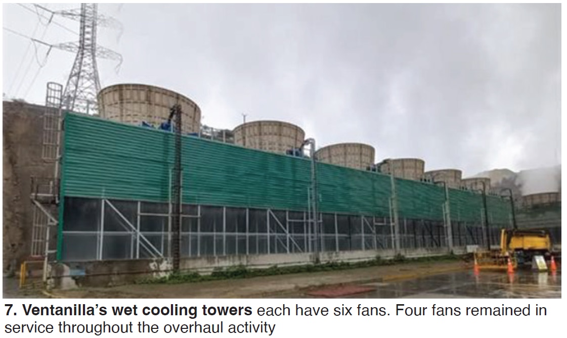
To increase air flow, it was necessary to stabilize the tower by reducing the vibrations attributed to worn/broken structural members. But because the entire structure was in poor condition, plant management decided to replace it, changing the structural material from wood to glass-reinforced plastic (Fig 8, left and center).

The upgrade work was conducted in a manner to keep the plant operating. This was done by removing only two cells from service at a time, leaving four in operation.
Also, to guarantee the circulating-water temperature at its design value of 2200 m³/h, the orifice plates for each cell in the six-cell tower were resized for a balanced supply condition and even distribution in all cells.
Result. Increasing cooling-air flow and changing fill improved tower performance to deliver 0.7 MW of increased generation. The financial impact was an additional $134,000 in energy production annually plus a $41,000 boost in capacity payments.
By removing two cells from service at a time, rather than all six, saved an estimated $6 million.
Enel project participants:
Ivan Jimenez, mechanical specialist and project manager
Carloandhre Pareja, mechanical supervisor
Marco Rivera, responsible person for plant maintenance
Sandro Garcia, responsible person for operational optimization
Jose Soto, operational optimization specialist
Richard Mejia, safety supervisor
Ventanilla 2023 Best Practices
- Online monitoring alerts to transformer issues, protecting against a forced outage at Ventanilla
- HRSG deep cleaning with dry ice pellets at high pressure meets Ventanilla’s expectations
- Cooling-tower upgrade increases electric generation at Ventanilla
- Tighter control of circ-water chemistry improves economics, safety at Ventanilla

Ventanilla Combined Cycle Power Plant
Owned and operated by ENEL Generacíon Perú
427 MW, 2 × 1 SGT6-4000F-powered dual-fuel powerplant, located in Callao, Perú
Plant manager: Dany Alcantara
Plant background. Endesa SA, Spain’s largest electric utility, won a tender in December 1995 to take control of Empresa de Generación Termoeléctrica de Ventanilla (Etevensa), the genco operating the Ventanilla thermal plant in Perú’s Callao Province, Lima Region. Etevensa had been spun off from Electroperu SA.
Endesa was the lead company in Consorcio Generalima, which also included two Peruvian companies. According to Christopher Bergesen, a Maryland-based consultant with deep knowledge of the global electric power business, the consortium bid $US120 million and agreed to modernize the plant.
The plant was upgraded in 1997 when the OEM of record supplied and installed a pair of 170-MW gas turbines, replacing the 110-MW 501D5 engines installed in 1993.
Endesa took full control of Etevensa in August 2003 and the following year converted Ventanilla to combined-cycle operation by adding a supplementary-fired HRSG downstream of each GT and a 184-MW steam turbine.
In September 2004, Ventanilla, now owned and operated by Endesa successor company Enel Generación Perú, began burning Peruvian gas and producing power for distribution via the national grid. In January 2021, Enel commissioned a 14.6-MW battery energy storage system—Perú’s first—using lithium-ion technology.
Challenge. The water source for Ventanilla’s cooling towers is relatively poor-quality well water, requiring continuous blowdown and a high consumption of chemicals to maintain the recommended water chemistry. Cooling-water treatment in the plant’s early years consisted of the following:
- 98% sulfuric-acid for control of scaling.
- 10% sodium hypochlorite for microbiological control.
- Internal water treatment for scaling control involved:
- Automatic sulfuric acid dosing system.
- Manual dosing system for anti-scalant with regulation based on residual grab analysis in the plant laboratory.
- Manual water purge system with regulation based on periodic field measurement of specific conductivity in makeup and recirculation water.
The operator only measured online the pH to control sulfuric-acid dosage; the other systems were based on periodic measurements in the lab. They did not allow action to be taken in real time to optimize the chemical treatment without putting the condenser at risk of scaling problems.
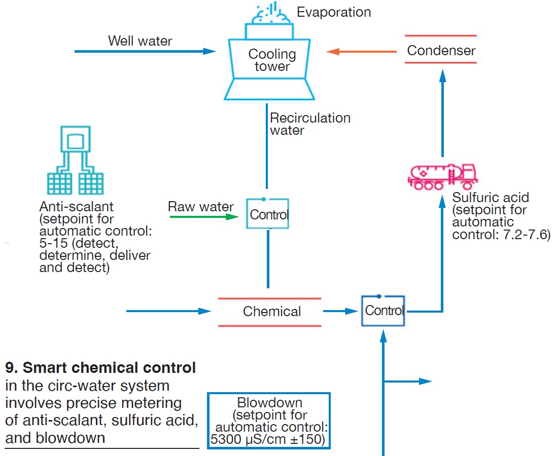
Solution. The Smart Chemical Control system described in Fig 9 integrated and enhanced the internal chemical treatment in the cooling tower thusly:
- Dosage of sulfuric acid at 98%, with the pH setpoint determined by the new chemical treatment, which controls starting and stopping of the acid pumps.
- Automatic cooling-tower blowdown control, with a recirculating-water conductivity setpoint determined by the new chemical treatment, which controls the opening and closing of the blowdown valve.
- Automatic dosage of the Nalco anti-scalant relies on a tracer in the recirculating water to control operation of the dosing pumps. This new treatment integrates and enhances the original treatment.
The three blocks and their controls are independent, making it possible to eliminate a type of failure that affects more than one unit. Water samples are taken weekly and physiochemical analyses conducted of hardness, sulfates, chlorides, pH, and specific conductivity.
Result. In the 2021-2022 period, Ventanilla saved $650,000 with its Smart Chemical Control program. The details: Reductions of 12% in makeup consumption, 7% in sulfuric acid, and 70% in anti-scaling chemicals, and a 25% saving in chemical handling time.
Enel project participants:
Jorge Tuya Rodriguez, chemical specialist and project manager
Juan Arteaga, chemical supervisor
Jose Gomez, I&C maintenance supervisor
Ventanilla 2023 Best Practices
- Online monitoring alerts to transformer issues, protecting against a forced outage at Ventanilla
- HRSG deep cleaning with dry ice pellets at high pressure meets Ventanilla’s expectations
- Cooling-tower upgrade increases electric generation at Ventanilla
- Tighter control of circ-water chemistry improves economics, safety at Ventanilla
By Steven C Stultz, Consulting Editor
The Ninth IAPWS European HRSG Forum (EHF 2023) took place in Prato, Italy, May 16 – 18. More than 80 attendees from 18 countries joined this event to discuss key global issues for combined-cycle owners, operators, plant personnel, service providers, and consultants.
EHF is one of three associated annual conferences that include the Australasian Boiler/HRSG Users Group (ABHUG) in Australia and the HRSG Forum in the US.
The meeting was organized by the International Association for the Properties of Water and Steam (IAPWS) and co-chaired by Barry Dooley, Structural Integrity (UK), and Bob Anderson, Competitive Power (US).
Below are selected highlights from EHF 2023. You can dig into the details of the presentations by requesting access here.
Carbon
For the first time at EHF, there were important presentations to address external environmental issues, namely carbon capture and hydrogen-blended fuels.
Jean-Francois Galopin, John Cockerill SA, Belgium, set the environmental stage early with Carbon capture aspects associated with combined-cycle/HRSG plants. He began with a review of global carbon-dioxide reduction initiatives and technology readiness levels for amine scrubbing/absorption, adsorption, use of membranes, and cryogenic distillation.
He then focused on carbon capture, utilization, and storage (CCUS), stating that “capture represents the largest portion of projects (47%), and storage is the largest output (27%) for the captured CO₂.”
Galopin included examples of combined-cycle projects by Scottish and Southern Energy (SSE) and others in the UK, and two planned projects in the US (Calpine Deep Park in Texas and James M Barry in Alabama).
A few key points from his review:
- The carbon market is booming, and tax incentives are growing worldwide.
- No single technology is currently superior across industries in all markets.
- Globally there are capture storage capacities of up to 50 years, but utilization needs to follow.
- Absorption with the help of amines is the most mature capture technology.
- Carbon is a cost. Capturing CO₂ in combined-cycle applications implies a loss of performance (an estimated 6% efficiency loss for 85% carbon capture).
On the following day, Cockerill’s Raphaël Stevens discussed efficiency improvements and CO₂ emissions reductions in middle-aged HRSGs. He presented a case study of four HRSGs at the 600-MW Fujairah desalination and power project in the United Arab Emirates.
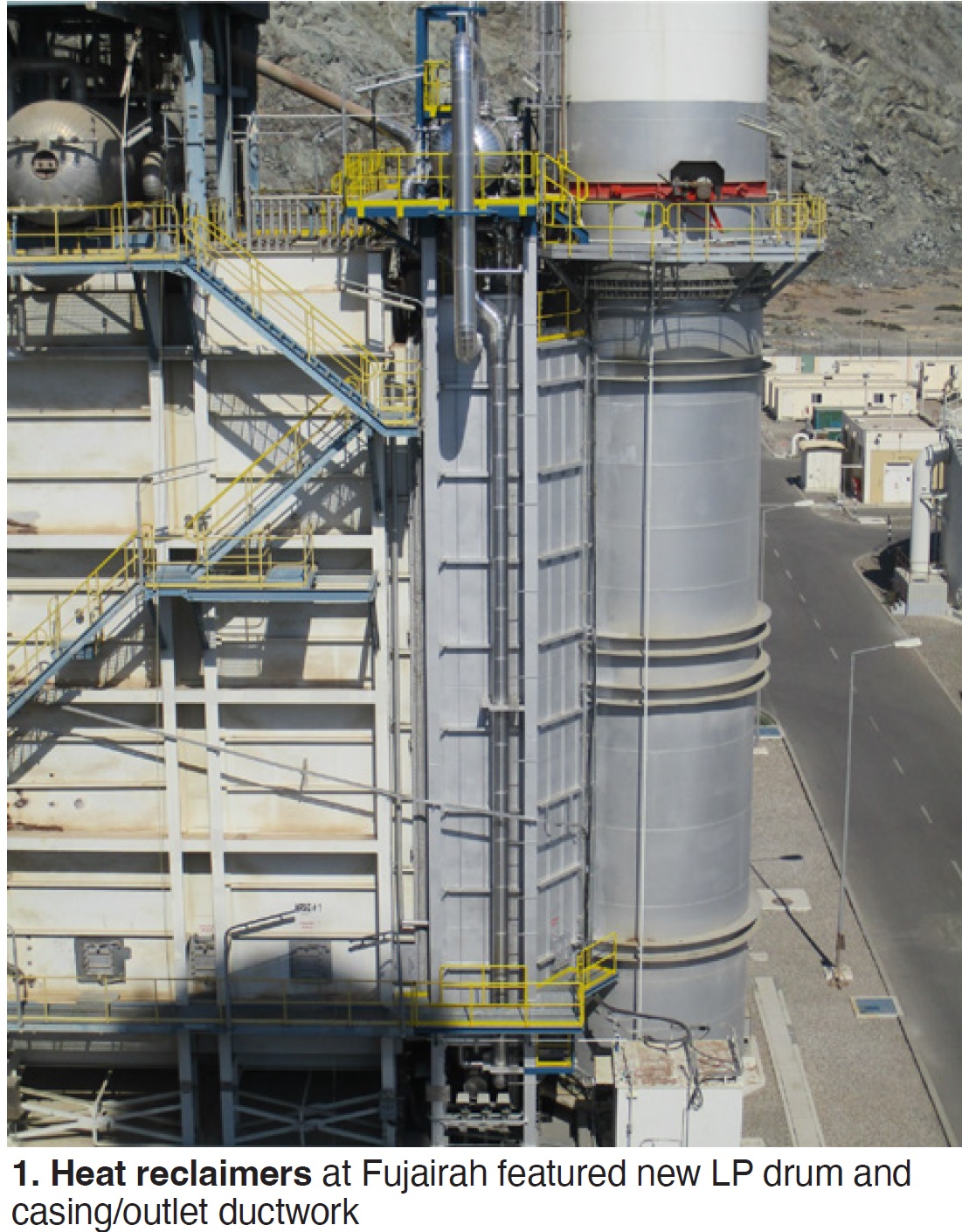
The objective is to retrofit a “heat-reclaimer” circuit within the outlet duct of each HRSG to recover surplus heat and improve unit efficiency, thereby reducing carbon emissions (Fig 1).
Project basics include:
- A new LP module (heat-reclaimer unit) between the HRSG and stack with a new LP drum and casing.
- A design that enables higher flexibility in desalinated water production while lowering carbon emissions.
Stack outlet temperatures were reduced from 178C to 134C. Anticipated total CO₂ reduction is 72,000 tons annually.
Hydrogen
NEM Energy’s Francesco Perrone presented The impact of hydrogen-fired gas turbines on HRSGs. He explained the significance:
- Use of hydrogen fuel blends in gas turbines is in full development worldwide.
- As gas turbines become hydrogen ready, owner/operators need to know the potential impact on HRSGs and other downstream systems and components.
Perrone offered some specifics on “the physics of hydrogen”:
- H₂ has a high mass-related heating value (LHV) of 120 MJ/kg, nearly two and a half times higher than methane.
- H₂ has a very low density, eight times lower than methane.
- H₂ may have a tendency to reduce ductility in carbon or low-grade steel (hydrogen embrittlement).
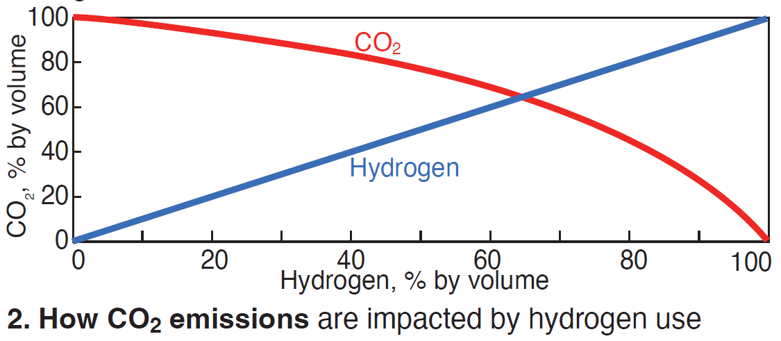
Also, according to Perrone, a blend of natural gas with 30% hydrogen can deliver about an 11% carbon reduction (Fig 2). One of his key points: “Hydrogen will be an important part of the future global power generation industry.”
He then offered these thoughts from an HRSG design and manufacturing perspective:
Safety. H₂ has a wider explosive-mixture range and lower ignition energy compared to natural gas, but considering that hydrogen’s auto-ignition temperature range is similar, no additional or different safety provisions are anticipated at this time.
However, Bob Anderson questioned this conclusion and suggested that the wider explosive mixture range, lower ignition energy, and lower density (causing H₂ to accumulate in attic spaces) may render current pre-start purge procedures ineffective.
Exhaust. Hydrogen co-firing may result in increased exhaust-gas volumetric flow and higher exhaust temperatures, and the HRSG must be designed to avoid exceeding the maximum allowable GT backpressure and overheating of HRSG pressure parts.
Emissions. Co-firing will most likely result in higher NOₓ emissions. Potentially more space should be considered for future H₂-ready SCR systems.
Condensation. Co-firing results in higher water content in the exhaust (a concern for the “cold end” of the HRSG). The water dewpoint will increase with hydrogen content, especially above 50%. In most cases this can be handled with feedwater recirculation by increasing the mean water temperature setpoint. Also, if sulfur content increases, acid dewpoint could become a corrosion concern.
Supplemental firing. Hydrogen co-firing is also possible in duct-burner systems. Considering LHV and supply pressure, special provisions may be required to make an existing duct burner H₂-ready.
Reheater tube failures, remedies
Thamarai Chevlan, Siemens-Energy, presented HRSG primary reheater tube failures and remedies. The subject was Limak Enerji’s 1200-MW Hamitabat Combined Cycle Power Plant in Turkey, commercial since 2017.
It features two Siemens SGT5-8000H gas turbines and two CMI triple-pressure horizontal-flow HRSGs. The original base-load design has been in cycling mode since commissioning.
HRSGs in both units suffered tube leaks in the primary (RH1) and final (RH3) reheaters after four years of operation. Primary-reheater tube failures (T22 material) occurred in the header-module end tubes. Final-reheater failures (Type 304 stainless steel material) were in tubes directly below the outlet headers. These tubes are connected with safe-end P91 nipples to the P91 headers (Fig 3).
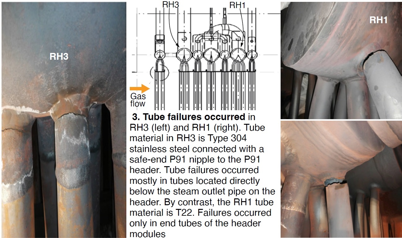
Root cause of the RH1 failures was low-cycle thermal fatigue created by frequent cycling and temperature fluctuations which were attributed to poor attemperator control logic, leading to high-temperature oxidation and exfoliation in T22 tube materials.
Analysis also found misalignment of reheater headers during installation, and multiple failed parallel plates allowing gas flow bypass to the end tubes, raising the metal temperatures.
Root cause of the RH3 failures was low-cycle thermal fatigue caused by cycling, dissimilar metals (P91 and Type 304 stainless steel), and differential metal temperatures along the length of header producing differential expansion between adjacent tubes.
Chevlan reviewed the five stages of high-temperature oxide growth and exfoliation index in RH1 T22 tubing. He also provided a backgrounder on the parallel-baffle failures.
Cracked T22 tubes were replaced with P91, the short safe-end nipples on RH3 were replaced with longer T91 tubes, and gas bypass was minimized.
The following day, Sergio Gómez, BBE Spain, offered Oxide growth and exfoliation (OGE) and other related mechanisms in the reheater of a combined-cycle HRSG boiler. His presentation focused on the troubleshooting process—including leak detection, thermocouple installation, oxide thickness investigations, and metallographic studies.
Gómez’s case study was an 800-MW plant, commercial since 2003, near Bilbao, featuring two GE 9FA+e gas turbines and a D11 steam turbine. The triple-pressure HRSGs were designed by Nooter/Eriksen and manufactured by Babcock Wilcox Española.
A key damage factor is increased plant cycling with more starts and fewer annual hours than predicted.
As discussed during EHF 2019, reheater leaks (RH2) were attributed to oxide growth and exfoliation, and a key inspection indicator was discoloration of a failed tube and the end of the header (Fig 4).
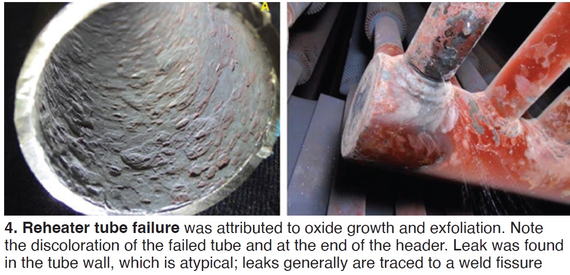
Tube-failure maps indicated high oxidation and exfoliation in the inner and outer surfaces, and cracked tubes in gaps between modules and in the gaps between harps and casing sidewalls. Tubes at gaps operate at higher metal temperatures because of exhaust gas bypassing through the gaps.
Current status shows OGE in all tubes (cracked and non-cracked) and cracks corresponding to thermomechanical fatigue.
Design variations are now being reviewed for component replacement at the end of 2023.
Other topic-related presentations at EHF 2023 were:
- EMUS-4 STRESS—A thermal-fatigue monitoring technique using electromagnetic acoustic transducers, by Framatome et al.
- The importance of careful assessment of aging HRSG HP superheater and reheater headers, by HRST.
- Creep-rate monitoring by diametrical measurement on superheater and reheater outlet manifolds and high-temperature pipes on combined-cycle gas turbines, by EDF France.
Attemperation
Bill Kitterman of SVI/Bremco offered Attemperators—repairs and replacements with detailed case studies on the challenges of attemperator location, orientation, pipework materials, dimensional differences between old and new equipment, crane access, and the solutions developed to replace several reheat and hot-reheat (HRH) attemperators.
A key element in successful implementation was focused and detailed planning and collaboration between contractors and plant personnel.
During replacements, new support steel was fabricated and installed. One new attemperator (HP1, horizontal) was longer than the original and one of the hanger/guides had to be moved. Existing spray-water piping was modified and an isolation valve was added.
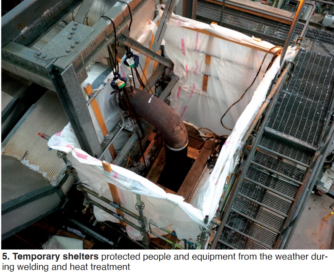
A new vertical HP attemperator was also required. Support steel had to be removed and temporary supports added. Daily meetings were held with regard to staging, insulation, weather containment, heat treatment, crane, and welding contractors to best use resources. Temporary shelters (Fig 5) were built to protect equipment and personnel from weather during welding and heat treatment.
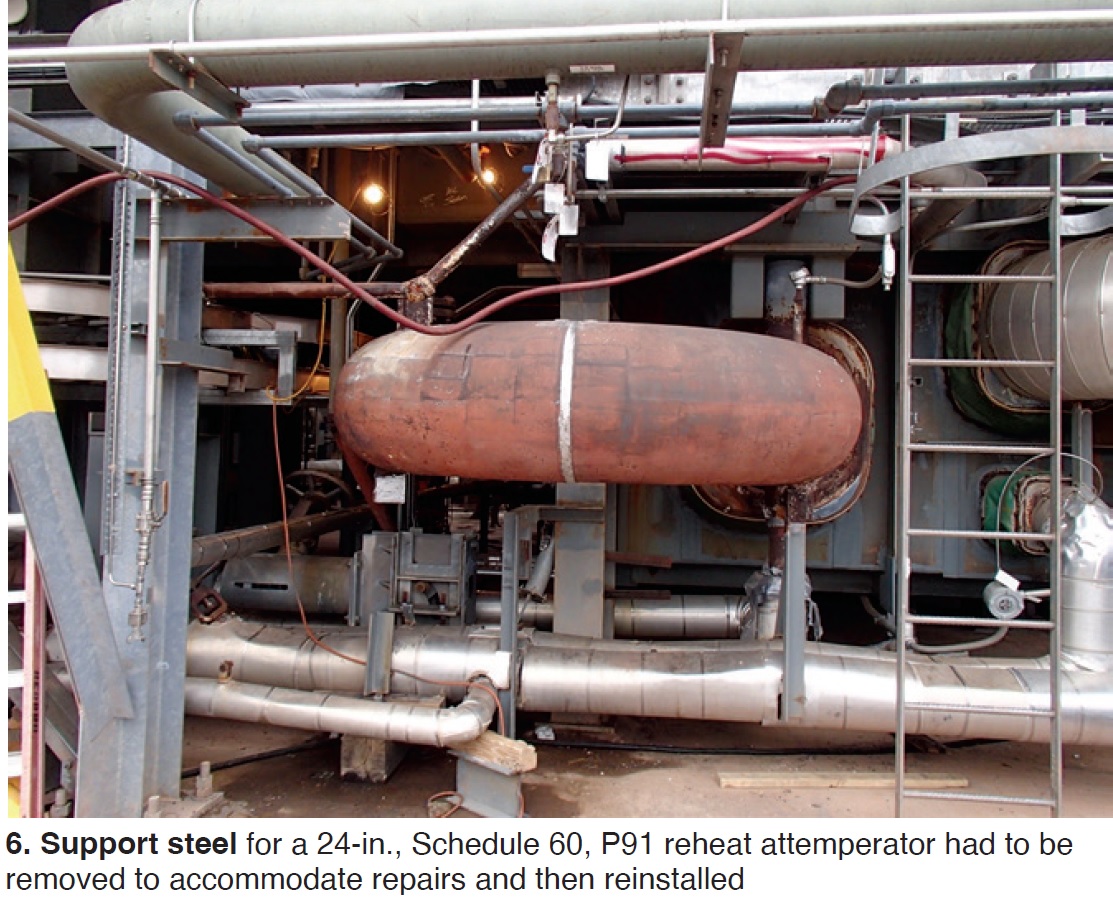
The P91 HRH attemperator was installed beneath the HRSG, requiring removal and reinstallation of support steel (Fig 6).
Denis Funk, Flexim, Germany, offered Attemperator leak detection to prevent steam tube damage describing case studies at multiple units using standard clamp-on ultrasonic flow meters for detection of leaking spray water.
Key takeaways:
- Easy installation requires no pipe penetrations or unit shutdown.
- Better accuracy and turndown than existing differential-pressure flowmeters.
- Some owners installed permanent meters for continuous monitoring to detect small leaks early.
Other owners used portable meters to test all attemperator valves quickly during shutdown.
Operational improvement. Also on Day One, Bob Anderson, Competitive Power Resources, discussed Improved attemperator control and startup procedure to avoid overspray and overshooting of HP superheater and reheater outlet temperatures, a concept developed and implemented by Dave Buzza, formerly of AEP, a major US utility.
This work is now part of EPRI Program 218, HRSG Fundamentals (Volume 4), Optimizing startup procedures and control logic for high-pressure and reheat steam attemperators [2021 Product 3002021149].
The premise: Some HRSGs have poorly designed HPSH and RH surface-area distribution before and after the attemperator. If there is too much surface downstream (secondary) relative to upstream (primary), it is difficult to avoid overspray and avoid overshoot HPSH/RH outlet steam temperatures. He stressed: “This design feature cannot be easily changed.”
Why is this discussion important today?
- GE F/H-class gas turbines have a very aggressive exhaust-temperature profile during HRSG startup.
- This profile makes it difficult to avoid overspray and HPSH/RH outlet-temperature excursions.
- Optional features, such as Variable Load Path, can mitigate the problem but most units do not have this feature.
Anderson discussed the typical legacy workaround: Reduce outlet-temperature setpoint (start spray sooner), and increase GT load as rapidly as possible through the Hot Zone to reduce the extent of temperature excursions (Fig 7).
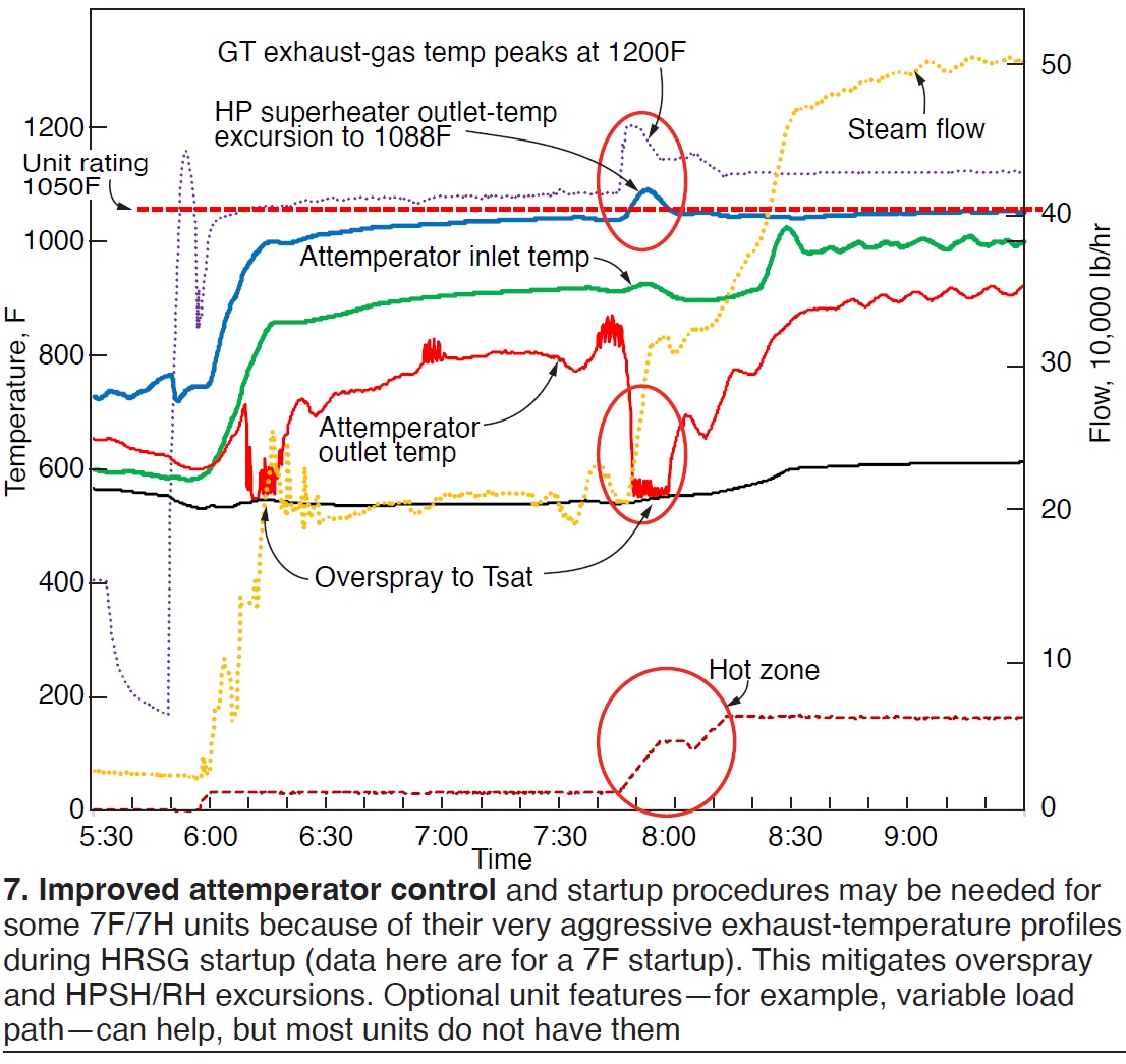
However, this can create a large upset of the attemperator control loop, and unstable operation. The result is overspray.
This presentation offered key features of an improved startup procedure:
- Ensure HPSH and RH are properly drained.
- Use exhaust-temperature matching (lead and lag units) for early outlet steam-temperature control.
- Maintain steam outlet-temperature setpoint at unit rating.
- Establish stable steam flow path before loading the gas turbine through the Hot Zone:
- Lead unit. ST operating on inlet pressure control with HP and HRH bypasses closed.
- Lag unit. HP, HRH, and CRH all blended into lead unit with HP and HRH bypasses closed.
- New attemperator’s “enable” permissive only opens spray block valve and control valve when outlet temperature reaches 5 deg F above steam outlet-temperature setpoint.
- Increase GT load in small increments (much less than 1 MW) until attemperator starts at unit rating plus 5 deg F. Attemperation will start without upset to provide stable spray flow and immediately lower the outlet temperature to unit rating.
- Hold GT load steady for a few minutes until steam flow stabilizes.
- Increase GT load in 1-MW steps to increase attemperator spray flow and decrease attemperator outlet temperature to predetermined target value (110 deg F above Tsat).
- Hold GT load steady for a few minutes to allow steam flow to stabilize. Attemperator is now operating with maximum available steam flow, substantial spray flow, and ready to react in a stable manner when loading through the Hot Zone.
- Unit is now ready to ramp GT load through the Hot Zone.
- No changes to ST, GT, or HRSG systems from 5 min before ramping until 5 min after ramping, such as:
- Ramping a second GT through the Hot Zone.
- Changing the ST inlet-pressure-control setpoint.
- Starting duct burners.
In addition to the procedure above, a feedforward model-based control logic is required. The new model-based attemperator control uses a table of attemperator outlet steam temperatures required as a function of HRSG heat input, which includes GT exhaust flow and temperature, and duct-burner fuel flow.
Attemperator outlet temperature values in the table range from 700F to 1000F resulting in highly accurate and stable control of HPSH/RH outlet temperatures.
Additional topic-related presentations at EHF 2023 included:
- Efficiency increase due to thermal-shock-free attemperators, by Advanced Valve Solutions.
- Development of innovative technology for attemperation in HRSGs, by EPRI.
- Ensuring reliable performance of turbine bypass systems in wet steam service, by Koso Parcol.
Cycle chemistry
Barry Dooley updated attendees on cycle-chemistry control and flow-accelerated corrosion. This included the latest chemistry-influenced reliability statistics referred to as Repeat Cycle Chemistry Situations (RCCS) which continue to show an overall global improvement.
However, further improvement is needed. RCCS data from 118 plants indicates that 86% of plants have ineffective corrosion-products monitoring programs, 80% have reduced cycle-chemistry instrumentation when compared to the international (IAPWS) standard, 78% fail to monitor drum carryover, and about 73% are not challenging the status quo.
On Day Three, one user presented a proactive approach to understanding and implementing state-of-the-art combined-cycle chemistry guidance, successfully bringing the cycle-chemistry control of their combined cycles up to world-class standards. Madrisse Yede, Azito, Côte d’Ivoire, presented Cycle chemistry at Azito Combined Cycle Power Plant, a 460-MW installation in Abidjan.
Yede’s presentation included:
- Initial chemistry guidelines from the EPC contractor.
- Customization of plant cycle chemistry.
- Current status and results achieved for control of FAC and steam purity.
His details included specifics of iron monitoring following the IAPWS technical guidance documents.
Alstom gas turbines were installed at Azito in 1999 and 2000. The plant became combined cycle with addition of a steam turbine in 2015. Azito now includes two Doosan dual-pressure HRSGs and one air-cooled condenser.
Both Alstom gas turbines received MXL2 upgrades in 2019.
Today, Azito runs baseload, providing 30% of Ivory Coast’s power production.
Yede outlined the initial chemistry: ammonia for condensate and feedwater, trisodium phosphate (TSP) in LP and HP drums to raise pH, and carbohydrazide (reducing agent) for control of oxygen level.
Customization over time has included improvement in online monitoring instrumentation and total iron monitoring.
The original reducing agent was seen as an FAC promoter and was discontinued. Injection of TSP was also stopped. There was sufficient alkalinity with ammonia, and this eliminated the risk of phosphate carryover.
Chemistry target values were adjusted. LP drum-level pH was increased to 9.7-10 for better FAC protection while maintaining phosphate levels at 5 to 8 ppm. The condensate pH window was increased from 9.2-9.6 to 9.7-10 to prevent two-phase FAC in HRSGs and the ACC.
Continuous online instrumentation was also added. In the LP drum, a phosphate analyzer was installed for better drum/evaporator control. In the HP drum, a CACE analyzer was added to monitor drum purity and optimize blowdown.
Total iron monitoring was implemented to assess whether the cycle chemistry is optimized and whether FAC is occurring. IAPWS target values were established at <2 ppb feedwater, <5 ppb in drums, and <10 ppb in condensate (CPD).
Stated Yede, “Instrumentation is now 100% of the IAPWS standard for fundamental instruments customized to dual-pressure HRSG units operating on AVT(O) and PT in LP drums.”
The plant has experienced no chemistry-influenced HRSG tube failures, and no steam-turbine phase-transition-zone damage. The plant just completed a full Thermal Transient Assessment.
Azito is now being expanded with a gas turbine, HRSG, and steam turbine to add 235 MW, for a total of 710 MW. It will become the country’s largest operating plant.
In a related presentation, GE Power Services presented Recent experience on water chemistry challenges on in-service HRSGs.
FFS. Dooley also offered The latest international activities on film-forming substances, both amine- (FFA) and non-amine-based (FFP). He stated that overall, global applications illustrate reduced corrosion-product transport and general protection in water-touched circuits, but questionable film formation in steam circuits. He offered the key pre-application procedures required to provide optimum results and prevent problems of under-deposit corrosion and “gunk” formation. Examples of increased HP-evaporator deposits and UDC were also provided in cases where FFS was applied in HRSGs with existing high internal deposit density.
One specific FFS-related presentation was Optimizing cycle chemistry and layup protection of a 420-MW Benson CCGT with non-amine-based surface-active chemistry by Lubica Moravokva, ZSE, Slovakia. This featured the 410-MW single-shaft combined-cycle powerplant Malzenice which was mothballed from 2013 to 2018. Current operation is irregular/peak load.
In the HRSG, flow-accelerated corrosion has recurred in the LP and IP systems. The primary current issue is magnetite deposition in the HP evaporator attributed to two-phase FAC.
Ongoing operation will be cycling with unknown periods of standstill.
Plant design is AVT/OT chemistry, and Moravokva offered a chemistry review:
- Increased ammonia or oxygen injection is not seen as effective.
- Dosing of a solid alkali to IP and LP increases risk of TSP carryover.
- Film-forming chemistry is recommended for materials protection.
The plant considered two film-forming substances: a film-forming-amine product based on OLDA, and Anodamine HPFG (an FFP).
Since the end of 2021, Malzenice has been dosing Anodamine HPFG as an enhancement to the applied ammonia/OT chemistry in the water/steam cycle. Dosing is in the condensate line to a final rate of 1.5 to 1.2 ppm.
Visual inspection results were offered on hematite and hydrophobicity.
His summary and conclusions:
- Inspections have shown successful application and improved protection of visible areas.
- Steam purity has remained within OEM limits.
- The plant predicts an improved startup curve, with less iron content and lower potential damage (including to the valves).
In a related presentation, Reicon’s Ronny Wagner offered [IT] Improved preservation and flexible powerplant operation with FFAs [RM]. He provided a case study of an 800-MW combined-cycle plant in Germany, offering these conclusions following injection of FFAP (Odacon) in the main condensate line after the condensate pump:
- Iron concentration during restart in the IP section was reduced by 70%.
- Nitrogen injection for short-term protection and drying for long-term protection are no longer required.
Tube gas-side cleaning
Three presentations focused on HRSG tube cleaning:
- KinetiClean™—A new, patented HRSG cleaning method, by Groome Industrial Service Group.
- PressureWave+ deep cleaning, by Bang & Clean Technologies.
- An independent HRSG inspector’s evaluation guide to various commercially available tube-cleaning methods, by Siemens-Energy.
Thermal transient update
Continuing a key feature of all related HRSG events, Bob Anderson presented an Update and statistics on HRSG thermal transients with a global perspective.
These international updates based on surveys at 64 plants between 2009 and 2022 included the following:
- 91% of 64 surveyed plants have no management policy to determine the root cause of HRSG tube failures so that repeat occurrences can be avoided.
- Management at 31% of surveyed plants permit operators to manually manipulate attemperator controls—a practice known to cause quench cracking of downstream pipework.
- Only 12% of surveyed plants perform routine inspection/maintenance of attemperator hardware to find or repair damage before pressure-part failure occurs.
- 82% of surveyed plants experience attemperator spray water leaking sufficiently severe to appear in DCS operating data. Leaking spray water during startup/shutdown/hot layup is known to be a major cause of cracking in steam pipework and tube failures.
- 93% of surveyed plants use master control/martyr block spray valve logic—a practice known to accelerate spray-water leakage.
- HPSH/RH drains fail to adequately remove condensate in 59% of surveyed plants—a condition known to cause tube failures.
Additional presentations at EHF 2023:
- Control valve myth-buster, by Emerson.
- Drum level instrumentation compliance with PED and ASME requirements and maximizing service life, by Clark-Reliance.
- An update and summary of penetration seal solutions for HRSGs, by Dekomte.
Sponsors and a look ahead
Sponsors for EHF 2023 were Advanced Valve Solutions, Bang & Clean Technologies, Clark Reliance, Dekomte, HRST, Koso Parcol, and Precision Iceblast Corp. EHF 2024 will be held in Prato, Italy, May 15-17, 2024. Visit https://europeanhrsgforum.com/ for more information.
By Steven C Stultz, Consulting Editor
The sixth annual IAPWS Conference on Film Forming Substances, held March 21-23 (2023) in Prato, Italy, was chaired by Barry Dooley of Structural Integrity Associates (UK) and David Addison of Thermal Chemistry (New Zealand). FFS conferences, sponsored by the International Association for the Properties of Water and Steam, are unique, as evidenced by the focus here on this narrow topic in cycle-chemistry control of powerplants and steam generating facilities.
Film forming substances consist of two main categories of chemicals using the internationally accepted nomenclature: amine-based (FFA, Film Forming Amine, and FFAP, Film Forming Amine Product) and non-amine-based (FFP, Film Forming Products) which are proprietary compositions.
There had been general confusion on the nomenclature, but these terms introduced by IAPWS in 2016 have quickly become the global standard. For background, see CCJ’s report on the Fifth International Conference and “Protection of metal surfaces: A wakeup call on film-forming substances.”
In 2023 the conference attracted 70 participants from 28 countries which included 20 plant operators/users and representatives from 11 FFS chemical suppliers.
As stated by Dooley, “The major activities at FFS 2023 were multiple presentations and discussion sessions outlining the current knowns and unknowns about FFS and their properties in relation to their application as corrosion inhibitors in fossil, industrial, nuclear, and other water/steam plants. Key research needs were documented by the conference attendees, which included the majority of global FFS suppliers, multiple users, research groups, and independent industry experts.”
Below are notes and background for owners/operators of combined-cycle and other powerplants, in particular those facing the increasing need to protect their equipment and systems during recurring on/off cycles and layup.
The launch
Dooley and Addison launched the conference with an overview and some significant timely points. Interest remains paramount on the following potential benefits of FFS:
- Shutdown protection under wet and dry conditions.
- Avoiding boiler and HRSG tube failures from under-deposit corrosion and corrosion fatigue.
- Arresting both single- and two-phase flow accelerated corrosion (FAC).
They also launched the proceedings with a clear picture of future fundamental work requirements, including but not limited to:
- Recognition that much current work is on metal surfaces rather than on the oxide surfaces.
- Effect of FFS on growth mechanisms of Fe, Cu, and Cr oxides in water and steam.
- Uncertainty of stability limit and decomposition products for all FFA and especially FFP.
- Information on changing from one FFS to another.
Again, this is only a partial list. The opening presentation gave relevant details of each.
Dooley ended the launch with two Cardinal Rules:
Rule 1. Make sure plant chemistry is optimized before application of an FFS.
Rule 2. Conduct a complete review (due diligence) before an FFS application.
Note that comprehensive guidance on the use of FFS is openly available through IAPWS. Go to http://www.iapws.org/techguide/FFS-Industrial.html. Section 8 of TGD8-16(2019), pp 19-32, provides operational guidance for operators/users on the continuous addition of an FFS.
An HRSG in Spain
Andre de Bache, Kurita, gave a brief history of Cetamine® leading to Cetamine G85X, a single-component FFA based on OLDA (Oleyl propylenediamine). He followed with a specific example of Cetamine treatment for a 400-MW HRSG in Spain facing continuous startups and shutdowns. The original baseload water-treatment plan was giving very poor corrosion protection.
The NEM HRSG was commissioned in 2005. As a direct result of cycling, inspection results between 2017 and 2020 revealed generalized FAC on various internal surfaces, and gradual wall thickness decrease from inside LP evaporator tubes.
FFS dosing began in 2021. Resulting cation conductivity reports, particle counts, and blowdown water consumption were reviewed in detail.
Bache’s conclusions: Cetamine G85X is offering beneficial protection during both cycling operation and preservation periods. It can be used as an additional treatment to conventional AVT or AVT+PT. It has reduced startup times and need for blowdown.
Steam condenser efficiency
Later in the day, Mahesh Budhathoki, Veolia, discussed steam-condenser efficiency improvements in a combined cycle using FFAs. This presentation began with descriptions of Polyamine Plus’ (PAP) potential advantages to power producers—including the following:
- Offers a beneficial layup method when not using nitrogen.
- Allows faster startups.
- Reduces chemical cleaning expense.
- Provides general corrosion and FAC protection during operation.
Case study premise: The method tested allows complete system protection from a single feed point and improves condenser performance and efficiency. A driving factor seemed to be an increase in dropwise condensation (Fig 1).
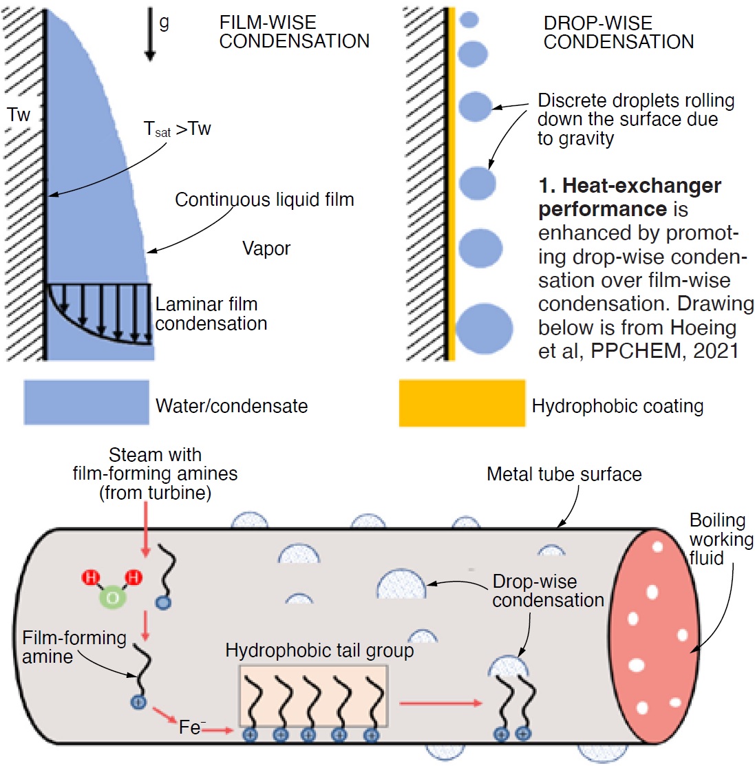
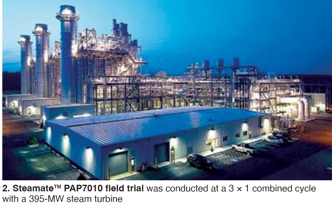
The case history focused on shell-and-tube condenser cleanliness factor (CCF) using Steamate™ PAP7010 at an 885-MW US combined cycle equipped with a 395-MW steam turbine (Fig 2). Over a three-month period, CCF increased by 1.6%, and condenser backpressure was reduced by 0.6 in. Hg. This led to “improved condenser performance, lower fuel consumption, and (therefore) reduced carbon emissions.”
The study was based on research that suggests:
- The FFA investigated can enhance the performance of heat exchangers constructed of various metal surfaces by promoting dropwise condensation (DWC), and importantly,
- DWC may not be achieved if FFA levels in steam and on the surface are not properly balanced.
Closed cooling system
One presentation focused on FFS in auxiliary closed cooling-water systems in Israel. The presentation by Yitzhak Nussbaum, Ezom, discussed various components comparing traditional treatment versus FFS. This complex site contains many systems, equipment from many OEMs, many materials, and a wide range of piping sizes and velocities.
Previous application was NaNO2/sodium nitrite from 2015 to 2018. FFS began in 2018.
This detailed presentation concluded the following:
- FFS is a reliable anti-corrosion treatment in closed cooling-water systems.
- Working with FFS, especially in the early stages, requires patience and careful monitoring.
Food industry lab study
Discussing the food industry, Julia Jasper, Kurita Europe, addressed what she called the next generation of water treatment. Boilers in this industry have either direct or indirect steam contact to food, are either shell or watertube boilers, and traditionally use softened, RO, and demineralized makeup water.
Jasper’s presentation covered details of corrosion rates in condensate and boiler water during laboratory tests using coupons. Her predictions based on FFS laboratory experience:
- Reduced blowdown and water discharge.
- Energy savings.
- Protection against corrosion and scaling.
- Single-component product solution.
A related presentation, by Ricardo Valezquez, Fineamin, evaluated the effectiveness of Fineamin® 39F use in Mexico, highlighting advantages of the product specifically formulated for the food and beverage industry. This application is designed to prevent corrosion and buildup of scale in low-pressure, softened water systems.
Other industrial
There was an interesting presentation by Flow-Tech Chemicals (Israel) on the use of heat-recovery boilers in the fertilizer industry, and application of ODA-based FFAP in a combined-heat-and-power (CHP) facility.
The sulfuric acid plant (Fig 3) uses boilers and shell-and-tube heat exchangers to recover heat from the chemical process and provide steam to the plant. Occasional leaks in the heat exchangers allow acid into the steam/condensate.
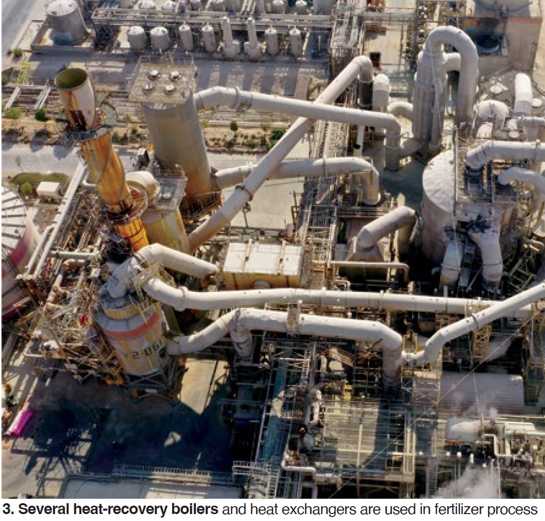
A blend of OLDA and alkalizing amines had been in place for 10 years. Field trials on a change to ODA-based FFAP for two boilers (15 and 25 MW) took place in 2022. Results of this FFS change were presented based on conductivity, pH, and iron transport.
Initial testing showed a substantial reduction in iron concentration of boiler water, well-protected steam and condensate lines, and validation of lab simulations for reduced short-loop condensate conductivity. Both heat-recovery boilers are now transitioning to Odacon®, a film-forming amine product by Reicon.
Nuclear
NPP Cernavoda in Romania consists of two 700-MW CANDU-6 nuclear units commissioned in 1996 and 2007. Unit 1 plans a midlife component refurbishment project in 2026 to include reactor fuel channels, calandria tubes and feeder, and HP turbine internals.
Unlike similarly aged plants, NPP Cernavoda will not replace the steam generators, given the improved tube materials and increased corrosion resistance designed into these units. Outage duration will be between 24 and 30 months, carrying high risk of standstill corrosion adversely impacting non-alloyed and low-alloyed carbon steels.
General corrosion could be caused by the presence of water on surfaces of systems and components, and oxygen which may be diluted in water or be present by air ingress. Selective localized forms of corrosion (specifically, pitting) could also occur. There is also the threat of corrosion transport during subsequent operation.
The presenter, from Framatome, suggested that standard layup methods, both wet and dry, have limitations. Therefore, the site has chosen FFS technology.
A project roadmap was presented on incorporating FFS into other outage activities, looking at all components and subsystems of the primary heat-transport system and water/steam cycle, plus all linked standby and auxiliary systems. FFS will be included for the feedwater system, reheater stage section after the HP moisture separator, steam generators, condenser, and deaerator. Updates on this important project will be presented at a future IAPWS conference.
Steam turbines
Jörg Kallweit discussed a biomass CHP plant in Luxembourg, highlighting its 8.4-MW turbine that was first examined and samples taken in 2020 (Fig 4). First option was online acid cleaning, second mechanical cleaning. However, the latter required turbine removal. A third option was online cleaning with FFS (amine-based FFA). Plant water treatment began in August 2022.
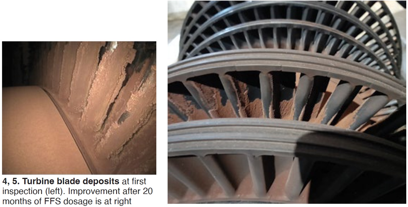
After 20 months, the following results were revealed:
Positive. Turbine output increased from 7.8 to 8.3 MW, with noticeable improvement in blade cleanliness (Fig 5).
Negative. An increase in acid conductivity in steam. The solution is to increase silica in the condensate. If conductivity remains high, boiler blowdown will be increased.
Some research details
Dooley explained in the conference launch that there is now a wide range of FFS products and mixtures from at least a dozen vendors globally. This increasing range makes research, derivation of common guidance, and solutions difficult. Most importantly, research is focused on the properties of adsorbed films.
Deni Jero represented a consortium from Université de Toulouse, Odyssee Environmental, Université Paris-Saclay, and Université de Bordeaux, for an in-depth look at adsorption kinetics in the presence of a reducing agent by electrochemical impedance spectroscopy. From the industrial perspective, the goal is to understand FFS barrier formation as a function of temperature in absence of corrosion products, and to provide a methodology for monitoring adsorption and corrosion kinetics.
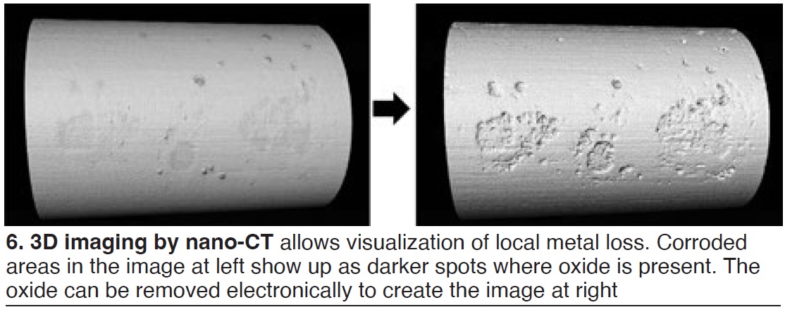
Andy Howell represented EPRI and gave details on tools that could characterize and evaluate the effectiveness of FFS in laboratory test projects—including scanning electron microscopy, X-ray spectroscopy, and other methods. He also discussed nano-computer tomography and analysis which can quantify local corrosion and visualize metal loss (Fig 6).
Universally, the presentations on applications of FFS to powerplants indicated reductions in the measurement of feedwater total-iron corrosion products. Some examples showed increase of CACE (conductivity after cation exchange). Mobilization of impurities (sulfate, for example) also was noted in some examples.
Scott Tucker, Hach, offered practical methods and best practices for monitoring iron-transport products and FFAs on a parts-per-billion basis, cautioning that “the lower you measure the more effect propagation of error will have on the results.” He added that “the sample is usually the greatest limiting factor in obtaining a true or representative result, especially at low-ppb values.” He presented Hach methods, equipment, and procedures with a focus on determining total iron.
Moving forward
On the third day, Thermal Chemistry’s David Addison began with a summary of the science and the unknowns, and a pathway to an IAPWS ICRN (IAPWS Certified Research Need) by the IAPWS Power Cycle Chemistry Group. When developed and issued, the ICRN hopefully will stimulate additional research related to FFS. See Dooley’s wrap-up analysis below.
Addison recapped the perceived and known benefits of FFS but was careful to point out the amount of work remaining.
Later that day, Wolfgang Hater (Germany) reiterated this with “Research needs for film forming substances applied in water/steam cycles,” tracing published research (primarily FFAs) back to the 1940s.
He summarized positive research developments by looking at these effects:
- Surface layers.
- Heat-transfer improvements in boilers and condensers.
- Droplet formation.
- Corrosion protection, copper and aluminum.
- Cleaning effect, mass transport.
- Ion-exchange resins, membranes (not yet conclusive).
He noted the remaining lack of reliable and conclusive data, suitable test concepts, and benchmarking.
Dooley’s wrap-up
In his review of the event, Structural Integrity’s Dooley included the following, pointing to the future publication of the ICRN by IAPWS. He stated:
“Overall and in the conference conclusion it was clear that the understanding of FFS application has improved worldwide since 2014 but that there is still a large amount of fundamental work needed to understand the mechanisms of the now wide array of FFS available for plant application. Up to now most research work has been addressed to ODA followed by OLDA; the secrecy associated with some of the FFP products remains an impediment for the industry.”
The following represents an outline of the research requirements which will be published in an IAPWS ICRN:
- Effect of FFS on growth mechanisms of Fe, Cu, and Cr oxides in water and steam. Better understanding will help to explain the effects of surface roughness and overdosing of FFS.
- Relation between surface coverage and degree of corrosion protection.
- Effect of FFS on boiler and HRSG tube failures (under-deposit corrosion and corrosion fatigue) and stress corrosion cracking.
- Film formation, kinetics, structure, equilibrium and stability (film thickness and porosity on water- and steam-touched oxide surfaces) for all FFS especially FFP.
- Thermolysis and decomposition products for FFA, and especially FFP, under oxidizing and reducing potential conditions.
- Uncertainty of adsorption onto oxide surfaces for all amine and non-amine FFS and how films are affected by other additions to the FFS. Characteristics of film layers and correlation with surface protection.
- Whether protection of superheated steam surfaces can be achieved for all amine and non-amine FFS.
- Increased steam-turbine performance for amine-based FFS (ODA) has been illustrated but research is needed to determine if FFS other than ODA reduce the surface tension.
- Can FFS improve steam-turbine efficiency and whether FFS, in general, can clean deposits from PTZ surfaces.
- Can FFS improve heat transfer in feedwater, boilers/HRSGs, and condensers.
- Impact of FFS on EDI and RO membranes.
- Impact of FFS on ion-exchange resins.
- Compatibility of FFS with other chemical additives (for example, chemical cleaning agents and dispersants).
- Relationship with any reduction of emissions.
FFS 2024
The FFS conferences are developed and supported by the International Association for the Properties of Water and Steam (IAPWS). FFS 2023 was arranged in Prato by Mecca Concepts (Australia) and the Combined Cycle Journal (US). The sponsors of FFS 2023 were Kurita Europe GmbH; Nalco Water, an Ecolab company; and Termanox Water Treatment Solutions.
Next year, the seventh FFS conference (FFS 2024) will be held March 26-28, also in Prato, Italy.
Contact Barry Dooley (bdooley@structint.com or bdooley@iapws.org) for further information on FFS and the IAPWS FFS conferences, or visit https://filmformingsubstances.com/ for more details.
By Vaughn Watson, Vector Systems Inc
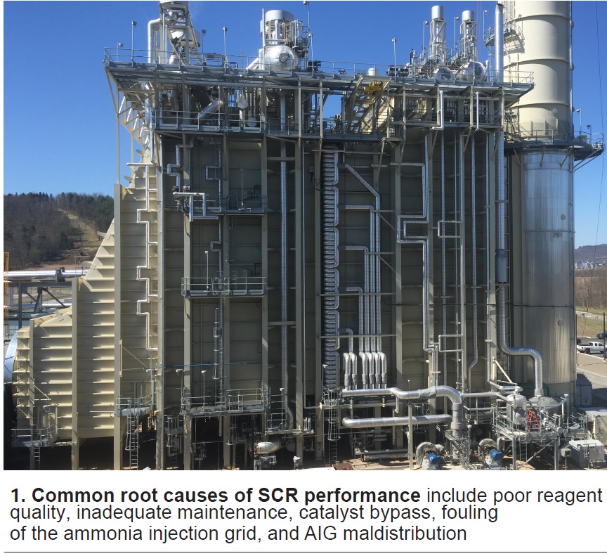
The long-term performance of an SCR system depends on the efficiency of its critical components (Fig 1). While the catalyst often gets all the credit, and all the blame when performance declines, proper maintenance and routine inspection of the ammonia system can alleviate and prevent many factors that contribute to SCR issues in your plant.
It starts with ammonia supply. It is important to work with a reputable and accountable chemical supplier to ensure you are getting the ammonia purity necessary for your system. One way to avoid ammonia contamination is to require dedicated trucks for each haul. Also, requiring certificates and test reports before offload is important for keeping the system free of contaminants like chlorides and calcium, which can damage and plug various ammonia-system components.
Specifying the correct purity grade of ammonia is critical. For aqueous ammonia systems, reagent-grade ammonia (99.95% NH₃ diluted by weight with demineralized water) is the best option. The key differentiation is the purity of the water content of the solution, which if not demineralized could contain soluble minerals that can plug, foul, erode, and damage SCR equipment. Impurities in the reagent solution can lead to vaporizer fouling, ammonia-injection-grid (AIG) plugging, and potential catalyst performance problems. It only takes one bad load of ammonia to experience the headaches associated with ammonia impurity.
For ammonia vaporizers, impurities can plug the spray nozzles or drip rings. They also can cause calcification that hinders vaporization efficiency and can lead to liquid reagent carryover. Channeling and plugging of the vaporizer can lead to NOₓ exceedances and excess ammonia usage.
For electric vaporization systems, inspections of the heater-panel components should be done to ensure all circuits and protective devices are functioning. Inspect the electric heater as well to ensure there is no water intrusion, which can affect heater resistance.
On hot-gas recirculation systems, rotate idle fans weekly, by hand or electrical bump of the motor, thereby ensuring all bearing parts are properly lubricated. Change bearing oil semi-annually using the specified lubricant and check oil levels regularly. Grease bearing seals annually (two or three pumps maximum) using the specified product. Do not use synthetic grease and do not over-grease. Too much grease can leak into the static oil lubricant. Open the coupling cover and regrease the coupling approximately every other month with the product specified.
Inspect the AIG for proper ammonia distribution every outage. Plugging of reagent ports can have a major adverse impact on catalyst performance. If plugging is found, the AIG should be cleaned and its root cause investigated. Note that AIG design can be improved to mitigate plugging and achieve better performance.
For example, specify Type 304 stainless steel for your AIG and eliminate burrs in drilled lances where chips might collect and salt could accumulate.
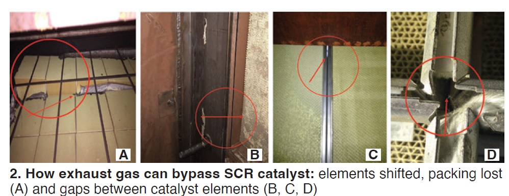
Catalyst should be inspected every outage to ensure its face is not blocked by rust or insulation. This can majorly affect catalyst performance by masking its active pore sites. The catalyst frame also should be inspected for any areas that may allow exhaust gas and ammonia bypass, which can greatly affect NOₓ and ammonia slip (Fig 2).
Ensuring these key maintenance and inspections are done regularly, and addressing problems when they are discovered, are essential to an efficient SCR system. To assist end users, Vector Systems offers comprehensive maintenance checklists for download at no charge for the following equipment:
The COMBINED CYCLE Journal and the steering committees of the industry’s leading users groups—including 7F, 501F, 501G, 7EA, 7/9HA, Western Turbine, CCUG, STUG, GUG, PPCUG, Frame 6B, Frame 5, 501D5-D5A, AOG, and V—collaborate to expand the sharing of best practices and lessons learned among owner/operators of large frame and aeroderivative gas turbines.
Thirty-eight plants listed below participated in the 2023 Best Practices Awards program with six selected by industry experts for Best of the Best honors. Details of the Best Practices submitted will be published in future issues.
CCJ launched the industry-wide Best Practices Awards program in late 2004. Its primary objective, says General Manager Scott Schwieger, is recognition of the valuable contributions made by plant and central-office personnel to improve the safety and performance of generating facilities powered by gas turbines.
Industry focus today on safety, outage management, and performance improvement—including starting reliability, fast starting, thermal performance, emissions reduction, and forced-outage reduction—is reflected in the lineup of proven solutions submitted this year.

2023 BEST OF THE BEST
Amman East Power Plant
Owned by AES Corp, Mitsui, and Neberas Power
Operated by AES Corp
- FAC encourages replacement of LP evaporator
- Overhead-crane lift safer with load display
- ACC washing system changes promote safer operation, improved performance
- Admin building HVAC operational improvement
Broad River Energy Center
Onward Energy
- Rigorous planning significantly improves outage results
H O Clarke, Topaz, and Braes Bayou
Owned by WattBridge
Operated by ProEnergy
- Modeling for successful proactive remote monitoring and diagnostics
- Seasonal shelters protect plant equipment in winter
- Roving work crews effectively support small onsite staffs
Exira Station
Owned by Western Minnesota Municipal Power Agency
Operated by Missouri River Energy Services
- Freeze-protection improvements assure high availability, reliable starts in winter
River Road Generating Plant
Owned by Clark Public Utilities
Operated by General Electric Gas Power
- HP steam drum leak repairs
- ‘Operator in Training’ program proves its value
- Operators receive reverse-osmosis specialist certification
- Racks simplify diaphragm handling, transport
Ventanilla Combined Cycle
ENEL Generacíon Perú
- Transformer monitoring in real time ensures reliable operation, improves safety
- HRSG tube cleaning restores lost performance
- Improved cooling tower water chemistry yields significant savings, environmental benefits
- Cooling tower upgrade enhances personnel safety, improves performance
2023 BEST PRACTICES FACILITES
AES Alamitos Energy and AES Huntington Beach Energy
Owned by AES Southland
Operated by AES Corp
AES Levant Peaker Power Plant
Owned by AES Corp, Mitsui, and Neberas Power
Operated by AES Corp
Athens Generating Plant
Owned by Kelson Energy
Operated by NAES Corp
Cape Canaveral Next Generation Clean Energy Center
Florida Power & Light
CC NORTE III
Owned by Abeinsa
Operated by NAES Corp
CPV Towantic Energy Center
Owned by Competitive Power Ventures
Operated by NAES Corp
CPV Valley Energy Center
Owned by Competitive Power Ventures and Diamond Generating Corp
Operated by DGC Operations LLC
Energía Del Valle de México II (EVM II)
Owned by Energia del Valle de Mexico Generador SAPI de CV
Operated by NAES
Essential Power Newington LLC
Owned by Essential Power Investments LLC
Operated by Operated by Cogentrix Energy Power Mgt
Fairview Energy Center
Owned by Osaka Gas USA, DLE, and Competitive Power Ventures
Operated by NAES
Faribault Energy Park
Owned by Minnesota Municipal Power Agency
Operated by NAES
Hunterstown Generating Station
Owned by Platinum Equity LLC
Managed by Competitive Power Ventures
Operated by NAES Corp
Jackson Generation
Owned by J-Power USA
Operated by NAES
Kings Mountain Energy Center
Owned by Carolina Power Partners LLC
Managed by CAMS
Operated by NAES
Kleen Energy Systems LLC
Owned by EIF Kleen, LLC
Operated by NAES
Lawrence County Generation Station
Owned by Hoosier Energy, REM, and Wabash Valley Power Assn
Operated by NAES Corp
Lee County Generating Station
Owned by Rockland Capital
Operated by NAES Corp
Linden Cogen
Owned by JERA Co, EGCO Group, Development Bank of Japan, and GS-Platform
Operated by NAES Corp
Mariposa Energy Project
Owned by Diamond Generating Corp
Operated by DGC Operations LLC
Milford Power
Owned by Starwood Energy Group Global and JERA Co
Operated by NAES Corp
Quail Run Energy Center
Owned by Starwood Energy Group Global
Operated by NAES Corp
REO Cogeneration Plant
Lansing Board of Water & Light
Rolling Hills Generating
Owned by LS Power
Operated by PIC Group
St. Charles Energy Center
Owned by Competitive Power Ventures
Operated by CAMS
Sentinel Energy Center
Owned by Diamond Generating Corp, Partners Group, and Voltage Finance LLC
Operated by DGC Operations LLC
Plant Wansley Combined Cycle
Southern Company
Wildflower Indigo Generation LLC
Owned by indirect affiliates of Diamond Generating LLC
Operated by DGC Operations LLC
Managed by DGC Asset Management LLC
Wildflower Larkspur Energy LLC
Owned by indirect affiliates of Diamond Generating LLC
Operated by DGC Operations LLC
Managed by DGC Asset Management LLC
Worthington Generation Station
Owned by Hoosier Energy
Operated by NAES Corp
Phoenix Rotor™ gives facility the best of both worlds
KEY POINTS
- Units returned to 200,000 factored fired hours
- Lengthy outages avoided
- CapEx savings of around 40% compared with a new rotor from the OEM
THE CHALLENGE: Going beyond rotor end of life
Gas turbine rotors have a finite lifetime. Heavy-duty gas turbine rotors in particular, like the GE Frame 7EA. Back in June 2007 (and later updated in 2011), the OEM issued a safety-critical Technical Information Letter (TIL) placing restrictions on running these units beyond 200,000 factored fired hours (FFH) or 5,000 factored fired starts (FFS).
TIL-1576 cites the risk of catastrophic failure and serious injury to nearby personnel. You could also face insurance claims being denied if you operate your units beyond these limits.
But for a power generation facility, the gas turbine is the key component. It’s the heartbeat of the entire operation.
So, plants with rotors approaching one or other of these end-of-life limits are faced with a tough decision: Do they buy an expensive new rotor from the OEM? Or do they purchase an aftermarket rotor that might not fit the operating timeline of the plant … and which often isn’t backed by warranty?
That was the position our client found itself facing in 2018. But, in fact, those weren’t the only two options available.
THE SOLUTION: Marrying the old with the new
Our client owns a cogeneration facility in the Gulf Coast area that supplies electricity and steam to an adjacent refinery. One of their GE Frame 7EA gas turbine unit rotors was a year or two away from reaching its end of life. But our client realized they would be operating that unit well beyond the estimated eight years offered by an aftermarket rotor.
The plant was looking for a life extension option that was low risk, cost-effective, flexible, and minimized downtime. It just so happened we had recently developed the ideal solution.
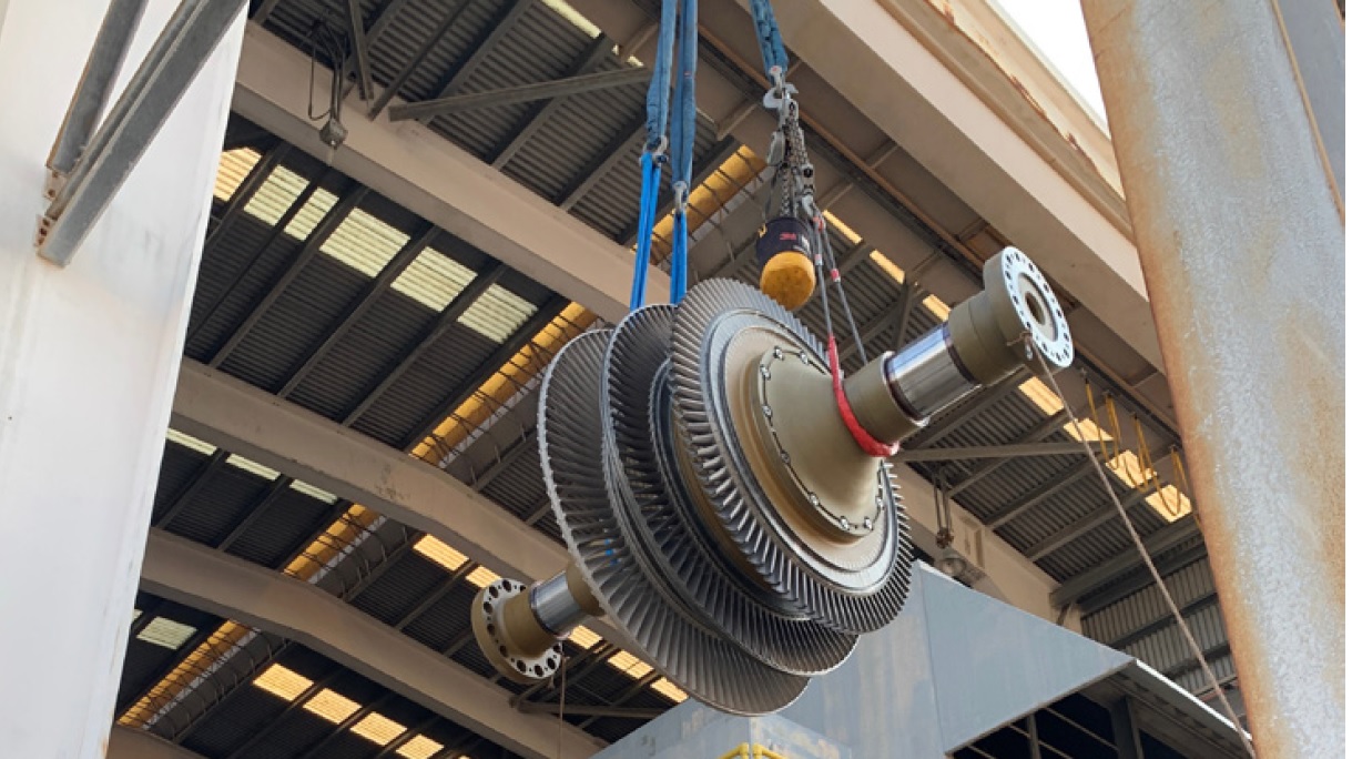
Our Phoenix Rotor™ gives clients the best of both worlds: long-term operation without the high costs of purchasing a brand-new unit from the OEM. Using new and CPOTM (certified previously operated) components, our hybrid 7EA rotor is certified for 200,000 FFH. In essence, it adds an additional 25 years to your unit.
Our client was open to our Phoenix Rotor solution but, given the magnitude of the decision, due diligence was a must. What they already had with us, however, was a relationship of trust built up over many years.
Going back to 2005, we had performed all their outages. We had carried out all their parts repairs and maintenance. And they relied on us for just about everything on their 7EA gas turbines. That included handling the purchase and installation of valves when they had changed from hydraulic to electric controllers.
Building on that platform, we walked our client through the know-how that informed our engineers’ thinking. We answered all their questions. And we gave them a warranty, demonstrating how much we stood behind our solution.
THE IMPACT: Adding another quarter of a century
With the client giving us the green light, we delivered and installed their first Phoenix Rotor on time. They then operated our rotor for a season without any issues. So pleased were they that they gave us the green light for a second rotor, which we installed the following year.
Now, nearly four years later, both rotors have been running without any issues. As have another eight Phoenix Rotors we’ve since installed for other clients.
Each of our rotors has given our client cost savings of around 40% compared with purchasing a new rotor from the OEM. And with a replacement they could drop in as soon as their old rotor was removed, they’ve avoided the potential for lengthy outages.
Not only have we regenerated the heartbeat of our client’s plant, but in the process we’ve cemented a relationship built on trust. By taking the time to listen to their wants and needs, we’ve shown them we truly are a partner who understands their business.
Learn more about rotor life extension and EthosEnergy’s other rotating equipment services and solutions at ethosenergy.com
Primex, the latest entrant into the field of operational anomaly detection and machine-learning (ML) services for gas-turbine-based plants, introduced its technology to the wider combined-cycle (CC) community through a series of four webinars held in June and July 2023. The legacy application of the technology has been for SO2 scrubber and BOP performance at coal-fired plants. The firm lists several big owner/operators as customers, several of which apply the service to CC units, and considers itself a services provider, not a software supplier.
ML, in its basic configuration, harnesses computing power to recognize patterns in large data sets, in this case the input and outputs of an operating system, either the entire plant, or its subsystems. ML first “trains” on the system to develop the baseline, or normal, operating patterns among the variables important to the system. Real-time data going forward is compared to the baseline to detect anomalies.
The technology is system agnostic—that is, it doesn’t care what the system is, just its streams of input and output data. However, deep domain expertise with the operating system is necessary to convert the ML results into actionable insights. For this and other reasons, the Primex team stresses that ML is not a substitute for human expertise. The technology pulls the data from the plant-wide data network, such as PI.
The webinars make a clear distinction between machine learning (ML) and artificial intelligence (AI) and they answer other questions commonly asked by powerplant managers. Many more questions remain and interested parties should contact Primex for additional information. This is typical for virtually all ML technology firms. The one requirement in ML pattern recognition is a stable baseline for comparisons, which may be difficult for CC units which start and stop frequently and cycle up and down in load.
Stewart Nicholson, founder, believes that the software offers more granularity and a deeper level of precision and confidence over traditional methods of analyzing performance–such as vendor performance curves. One example cited: An additional megawatt of output could have been worth nearly half a million dollars over 12 months (2021-2022) in the PJM market.
Use cases presented in the webinars include generation monitoring and diagnostics (for example, fault detection), performance optimization, predictive maintenance (for example, early warning of unusual degradation), performance comparison (such as before and after a major outage, or unit event like a GT water wash or HRSG chemical clean), generation and resource demand forecasting (improving bidding strategies and fuel procurement), and regional supply and demand forecasting.
“The service helps you make better decisions and make them sooner,” the experts conclude. Visit www.primexprocess.com for details.


