By Steven C Stultz, Consulting Editor
The Ninth IAPWS European HRSG Forum (EHF 2023) took place in Prato, Italy, May 16 – 18. More than 80 attendees from 18 countries joined this event to discuss key global issues for combined-cycle owners, operators, plant personnel, service providers, and consultants.
EHF is one of three associated annual conferences that include the Australasian Boiler/HRSG Users Group (ABHUG) in Australia and the HRSG Forum in the US.
The meeting was organized by the International Association for the Properties of Water and Steam (IAPWS) and co-chaired by Barry Dooley, Structural Integrity (UK), and Bob Anderson, Competitive Power (US).
Below are selected highlights from EHF 2023. You can dig into the details of the presentations by requesting access here.
Carbon
For the first time at EHF, there were important presentations to address external environmental issues, namely carbon capture and hydrogen-blended fuels.
Jean-Francois Galopin, John Cockerill SA, Belgium, set the environmental stage early with Carbon capture aspects associated with combined-cycle/HRSG plants. He began with a review of global carbon-dioxide reduction initiatives and technology readiness levels for amine scrubbing/absorption, adsorption, use of membranes, and cryogenic distillation.
He then focused on carbon capture, utilization, and storage (CCUS), stating that “capture represents the largest portion of projects (47%), and storage is the largest output (27%) for the captured CO₂.”
Galopin included examples of combined-cycle projects by Scottish and Southern Energy (SSE) and others in the UK, and two planned projects in the US (Calpine Deep Park in Texas and James M Barry in Alabama).
A few key points from his review:
- The carbon market is booming, and tax incentives are growing worldwide.
- No single technology is currently superior across industries in all markets.
- Globally there are capture storage capacities of up to 50 years, but utilization needs to follow.
- Absorption with the help of amines is the most mature capture technology.
- Carbon is a cost. Capturing CO₂ in combined-cycle applications implies a loss of performance (an estimated 6% efficiency loss for 85% carbon capture).
On the following day, Cockerill’s Raphaël Stevens discussed efficiency improvements and CO₂ emissions reductions in middle-aged HRSGs. He presented a case study of four HRSGs at the 600-MW Fujairah desalination and power project in the United Arab Emirates.
The objective is to retrofit a “heat-reclaimer” circuit within the outlet duct of each HRSG to recover surplus heat and improve unit efficiency, thereby reducing carbon emissions (Fig 1).
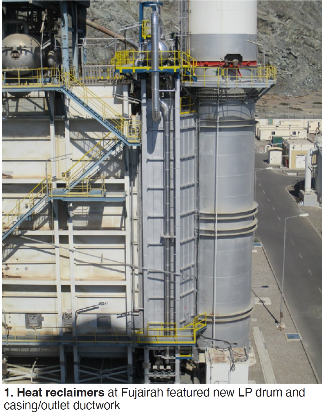
Project basics include:
- A new LP module (heat-reclaimer unit) between the HRSG and stack with a new LP drum and casing.
- A design that enables higher flexibility in desalinated water production while lowering carbon emissions.
Stack outlet temperatures were reduced from 178C to 134C. Anticipated total CO₂ reduction is 72,000 tons annually.
Hydrogen
NEM Energy’s Francesco Perrone presented The impact of hydrogen-fired gas turbines on HRSGs. He explained the significance:
- Use of hydrogen fuel blends in gas turbines is in full development worldwide.
- As gas turbines become hydrogen ready, owner/operators need to know the potential impact on HRSGs and other downstream systems and components.
Perrone offered some specifics on “the physics of hydrogen”:
- H₂ has a high mass-related heating value (LHV) of 120 MJ/kg, nearly two and a half times higher than methane.
- H₂ has a very low density, eight times lower than methane.
- H₂ may have a tendency to reduce ductility in carbon or low-grade steel (hydrogen embrittlement).
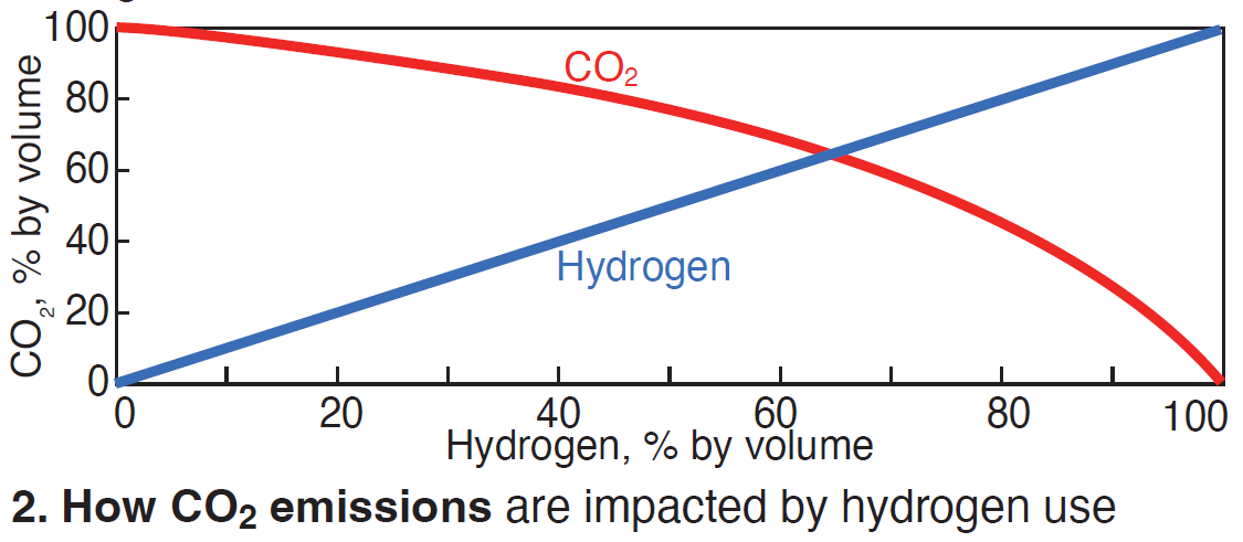
Also, according to Perrone, a blend of natural gas with 30% hydrogen can deliver about an 11% carbon reduction (Fig 2). One of his key points: “Hydrogen will be an important part of the future global power generation industry.”
He then offered these thoughts from an HRSG design and manufacturing perspective:
Safety. H₂ has a wider explosive-mixture range and lower ignition energy compared to natural gas, but considering that hydrogen’s auto-ignition temperature range is similar, no additional or different safety provisions are anticipated at this time.
However, Bob Anderson questioned this conclusion and suggested that the wider explosive mixture range, lower ignition energy, and lower density (causing H₂ to accumulate in attic spaces) may render current pre-start purge procedures ineffective.
Exhaust. Hydrogen co-firing may result in increased exhaust-gas volumetric flow and higher exhaust temperatures, and the HRSG must be designed to avoid exceeding the maximum allowable GT backpressure and overheating of HRSG pressure parts.
Emissions. Co-firing will most likely result in higher NOₓ emissions. Potentially more space should be considered for future H₂-ready SCR systems.
Condensation. Co-firing results in higher water content in the exhaust (a concern for the “cold end” of the HRSG). The water dewpoint will increase with hydrogen content, especially above 50%. In most cases this can be handled with feedwater recirculation by increasing the mean water temperature setpoint. Also, if sulfur content increases, acid dewpoint could become a corrosion concern.
Supplemental firing. Hydrogen co-firing is also possible in duct-burner systems. Considering LHV and supply pressure, special provisions may be required to make an existing duct burner H₂-ready.
Reheater tube failures, remedies
Thamarai Chevlan, Siemens-Energy, presented HRSG primary reheater tube failures and remedies. The subject was Limak Enerji’s 1200-MW Hamitabat Combined Cycle Power Plant in Turkey, commercial since 2017.
It features two Siemens SGT5-8000H gas turbines and two CMI triple-pressure horizontal-flow HRSGs. The original base-load design has been in cycling mode since commissioning.
HRSGs in both units suffered tube leaks in the primary (RH1) and final (RH3) reheaters after four years of operation. Primary-reheater tube failures (T22 material) occurred in the header-module end tubes. Final-reheater failures (Type 304 stainless steel material) were in tubes directly below the outlet headers. These tubes are connected with safe-end P91 nipples to the P91 headers (Fig 3).
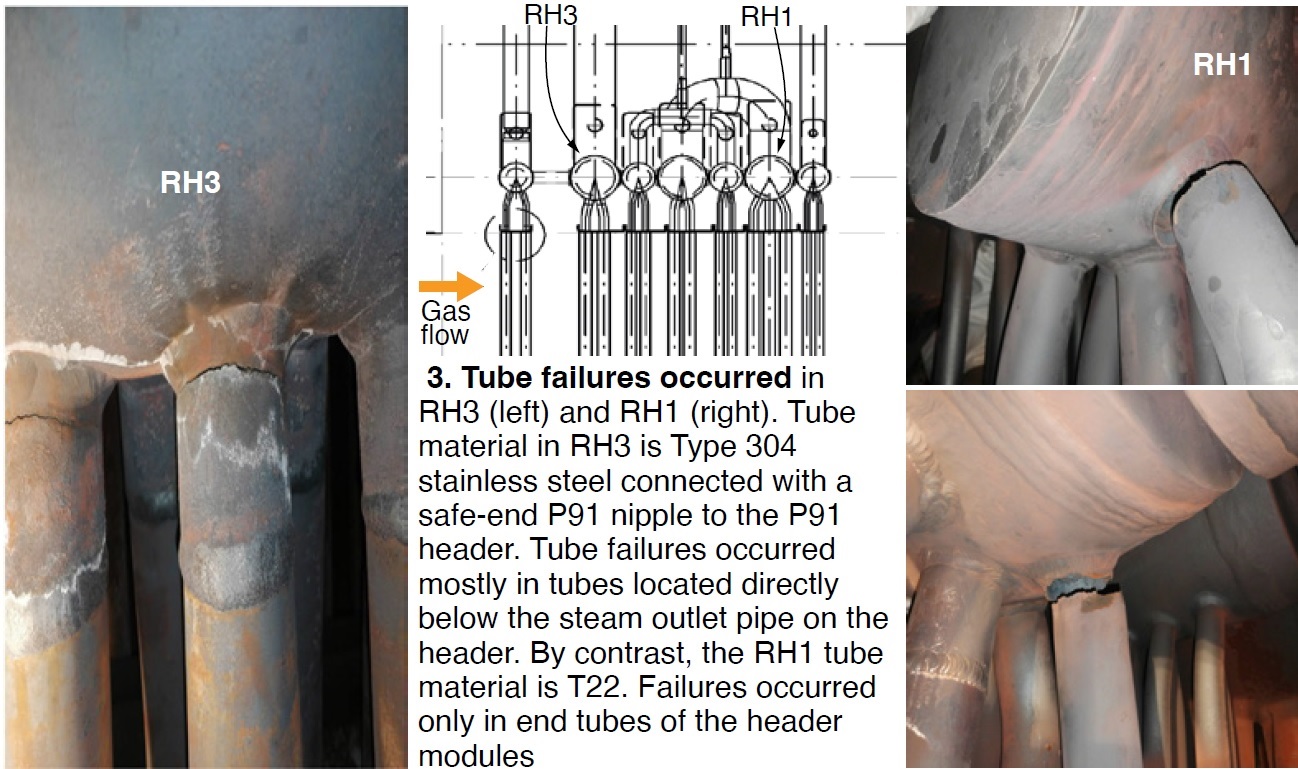
Root cause of the RH1 failures was low-cycle thermal fatigue created by frequent cycling and temperature fluctuations which were attributed to poor attemperator control logic, leading to high-temperature oxidation and exfoliation in T22 tube materials.
Analysis also found misalignment of reheater headers during installation, and multiple failed parallel plates allowing gas flow bypass to the end tubes, raising the metal temperatures.
Root cause of the RH3 failures was low-cycle thermal fatigue caused by cycling, dissimilar metals (P91 and Type 304 stainless steel), and differential metal temperatures along the length of header producing differential expansion between adjacent tubes.
Chevlan reviewed the five stages of high-temperature oxide growth and exfoliation index in RH1 T22 tubing. He also provided a backgrounder on the parallel-baffle failures.
Cracked T22 tubes were replaced with P91, the short safe-end nipples on RH3 were replaced with longer T91 tubes, and gas bypass was minimized.
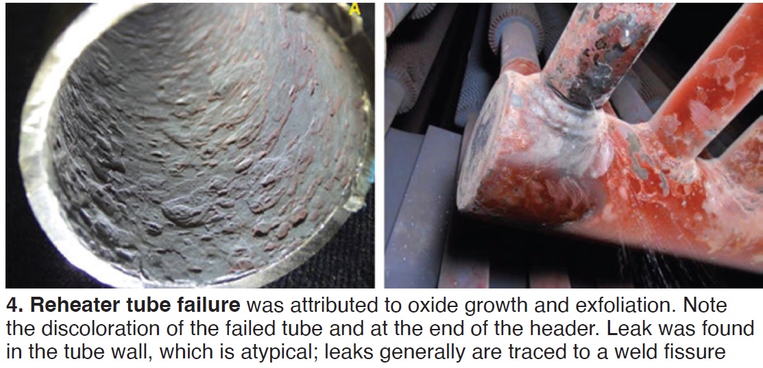
The following day, Sergio Gómez, BBE Spain, offered Oxide growth and exfoliation (OGE) and other related mechanisms in the reheater of a combined-cycle HRSG boiler. His presentation focused on the troubleshooting process—including leak detection, thermocouple installation, oxide thickness investigations, and metallographic studies.
Gómez’s case study was an 800-MW plant, commercial since 2003, near Bilbao, featuring two GE 9FA+e gas turbines and a D11 steam turbine. The triple-pressure HRSGs were designed by Nooter/Eriksen and manufactured by Babcock Wilcox Española.
A key damage factor is increased plant cycling with more starts and fewer annual hours than predicted.
As discussed during EHF 2019, reheater leaks (RH2) were attributed to oxide growth and exfoliation, and a key inspection indicator was discoloration of a failed tube and the end of the header (Fig 4).
Tube-failure maps indicated high oxidation and exfoliation in the inner and outer surfaces, and cracked tubes in gaps between modules and in the gaps between harps and casing sidewalls. Tubes at gaps operate at higher metal temperatures because of exhaust gas bypassing through the gaps.
Current status shows OGE in all tubes (cracked and non-cracked) and cracks corresponding to thermomechanical fatigue.
Design variations are now being reviewed for component replacement at the end of 2023.
Other topic-related presentations at EHF 2023 were:
- EMUS-4 STRESS—A thermal-fatigue monitoring technique using electromagnetic acoustic transducers, by Framatome et al.
- The importance of careful assessment of aging HRSG HP superheater and reheater headers, by HRST.
- Creep-rate monitoring by diametrical measurement on superheater and reheater outlet manifolds and high-temperature pipes on combined-cycle gas turbines, by EDF France.
Attemperation
Bill Kitterman of SVI/Bremco offered Attemperators—repairs and replacements with detailed case studies on the challenges of attemperator location, orientation, pipework materials, dimensional differences between old and new equipment, crane access, and the solutions developed to replace several reheat and hot-reheat (HRH) attemperators.
A key element in successful implementation was focused and detailed planning and collaboration between contractors and plant personnel.
During replacements, new support steel was fabricated and installed. One new attemperator (HP1, horizontal) was longer than the original and one of the hanger/guides had to be moved. Existing spray-water piping was modified and an isolation valve was added.
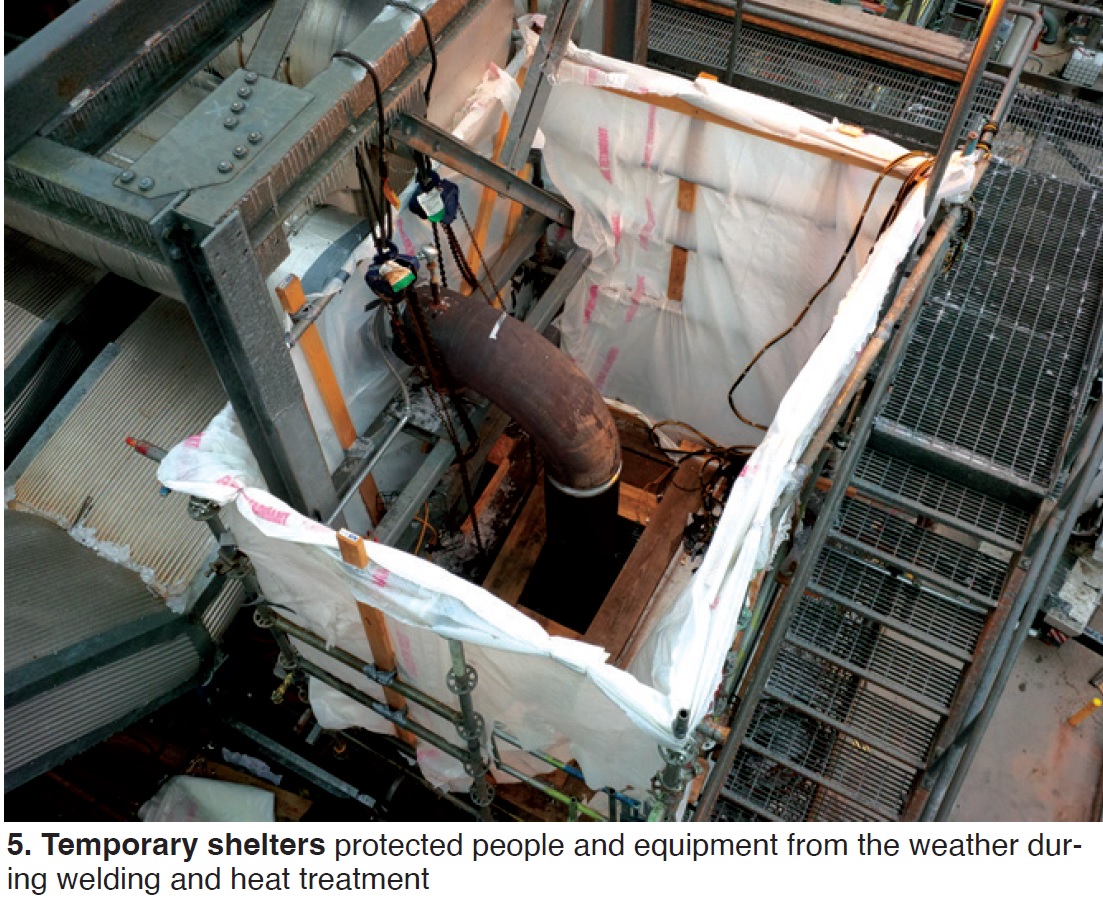
A new vertical HP attemperator was also required. Support steel had to be removed and temporary supports added. Daily meetings were held with regard to staging, insulation, weather containment, heat treatment, crane, and welding contractors to best use resources. Temporary shelters (Fig 5) were built to protect equipment and personnel from weather during welding and heat treatment.
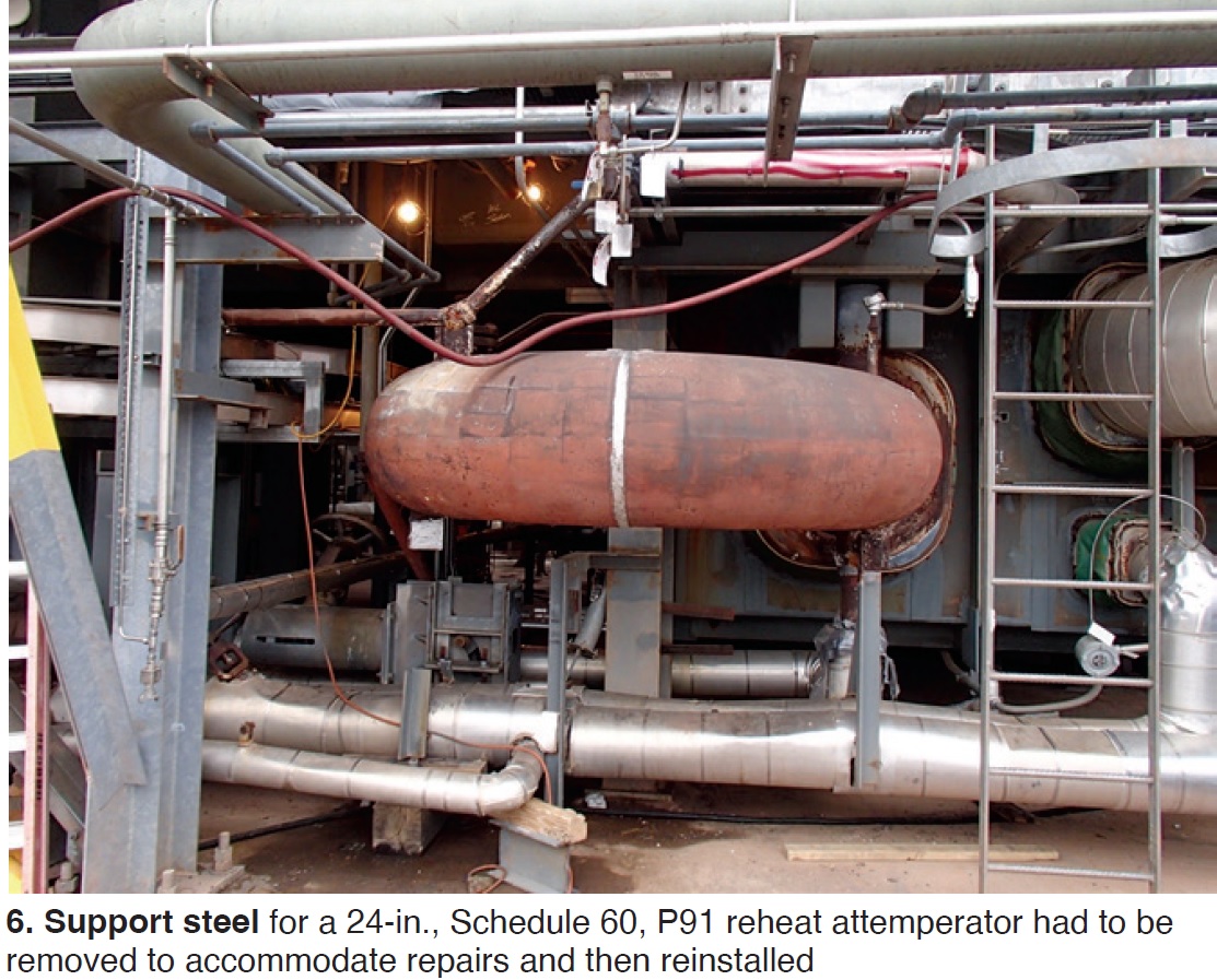
The P91 HRH attemperator was installed beneath the HRSG, requiring removal and reinstallation of support steel (Fig 6).
Denis Funk, Flexim, Germany, offered Attemperator leak detection to prevent steam tube damage describing case studies at multiple units using standard clamp-on ultrasonic flow meters for detection of leaking spray water.
Key takeaways:
- Easy installation requires no pipe penetrations or unit shutdown.
- Better accuracy and turndown than existing differential-pressure flowmeters.
- Some owners installed permanent meters for continuous monitoring to detect small leaks early.
Other owners used portable meters to test all attemperator valves quickly during shutdown.
Operational improvement. Also on Day One, Bob Anderson, Competitive Power Resources, discussed Improved attemperator control and startup procedure to avoid overspray and overshooting of HP superheater and reheater outlet temperatures, a concept developed and implemented by Dave Buzza, formerly of AEP, a major US utility.
This work is now part of EPRI Program 218, HRSG Fundamentals (Volume 4), Optimizing startup procedures and control logic for high-pressure and reheat steam attemperators [2021 Product 3002021149].
The premise: Some HRSGs have poorly designed HPSH and RH surface-area distribution before and after the attemperator. If there is too much surface downstream (secondary) relative to upstream (primary), it is difficult to avoid overspray and avoid overshoot HPSH/RH outlet steam temperatures. He stressed: “This design feature cannot be easily changed.”
Why is this discussion important today?
- GE F/H-class gas turbines have a very aggressive exhaust-temperature profile during HRSG startup.
- This profile makes it difficult to avoid overspray and HPSH/RH outlet-temperature excursions.
- Optional features, such as Variable Load Path, can mitigate the problem but most units do not have this feature.
Anderson discussed the typical legacy workaround: Reduce outlet-temperature setpoint (start spray sooner), and increase GT load as rapidly as possible through the Hot Zone to reduce the extent of temperature excursions (Fig 7).
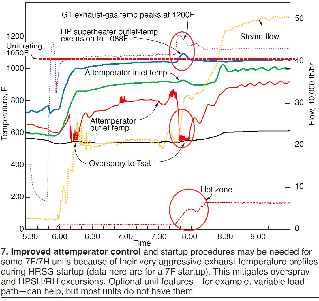
However, this can create a large upset of the attemperator control loop, and unstable operation. The result is overspray.
This presentation offered key features of an improved startup procedure:
- Ensure HPSH and RH are properly drained.
- Use exhaust-temperature matching (lead and lag units) for early outlet steam-temperature control.
- Maintain steam outlet-temperature setpoint at unit rating.
- Establish stable steam flow path before loading the gas turbine through the Hot Zone:
- Lead unit. ST operating on inlet pressure control with HP and HRH bypasses closed.
- Lag unit. HP, HRH, and CRH all blended into lead unit with HP and HRH bypasses closed.
- New attemperator’s “enable” permissive only opens spray block valve and control valve when outlet temperature reaches 5 deg F above steam outlet-temperature setpoint.
- Increase GT load in small increments (much less than 1 MW) until attemperator starts at unit rating plus 5 deg F. Attemperation will start without upset to provide stable spray flow and immediately lower the outlet temperature to unit rating.
- Hold GT load steady for a few minutes until steam flow stabilizes.
- Increase GT load in 1-MW steps to increase attemperator spray flow and decrease attemperator outlet temperature to predetermined target value (110 deg F above Tsat).
- Hold GT load steady for a few minutes to allow steam flow to stabilize. Attemperator is now operating with maximum available steam flow, substantial spray flow, and ready to react in a stable manner when loading through the Hot Zone.
- Unit is now ready to ramp GT load through the Hot Zone.
- No changes to ST, GT, or HRSG systems from 5 min before ramping until 5 min after ramping, such as:
- Ramping a second GT through the Hot Zone.
- Changing the ST inlet-pressure-control setpoint.
- Starting duct burners.
In addition to the procedure above, a feedforward model-based control logic is required. The new model-based attemperator control uses a table of attemperator outlet steam temperatures required as a function of HRSG heat input, which includes GT exhaust flow and temperature, and duct-burner fuel flow.
Attemperator outlet temperature values in the table range from 700F to 1000F resulting in highly accurate and stable control of HPSH/RH outlet temperatures.
Additional topic-related presentations at EHF 2023 included:
- Efficiency increase due to thermal-shock-free attemperators, by Advanced Valve Solutions.
- Development of innovative technology for attemperation in HRSGs, by EPRI.
- Ensuring reliable performance of turbine bypass systems in wet steam service, by Koso Parcol.
Cycle chemistry
Barry Dooley updated attendees on cycle-chemistry control and flow-accelerated corrosion. This included the latest chemistry-influenced reliability statistics referred to as Repeat Cycle Chemistry Situations (RCCS) which continue to show an overall global improvement.
However, further improvement is needed. RCCS data from 118 plants indicates that 86% of plants have ineffective corrosion-products monitoring programs, 80% have reduced cycle-chemistry instrumentation when compared to the international (IAPWS) standard, 78% fail to monitor drum carryover, and about 73% are not challenging the status quo.
On Day Three, one user presented a proactive approach to understanding and implementing state-of-the-art combined-cycle chemistry guidance, successfully bringing the cycle-chemistry control of their combined cycles up to world-class standards. Madrisse Yede, Azito, Côte d’Ivoire, presented Cycle chemistry at Azito Combined Cycle Power Plant, a 460-MW installation in Abidjan.
Yede’s presentation included:
- Initial chemistry guidelines from the EPC contractor.
- Customization of plant cycle chemistry.
- Current status and results achieved for control of FAC and steam purity.
His details included specifics of iron monitoring following the IAPWS technical guidance documents.
Alstom gas turbines were installed at Azito in 1999 and 2000. The plant became combined cycle with addition of a steam turbine in 2015. Azito now includes two Doosan dual-pressure HRSGs and one air-cooled condenser.
Both Alstom gas turbines received MXL2 upgrades in 2019.
Today, Azito runs baseload, providing 30% of Ivory Coast’s power production.
Yede outlined the initial chemistry: ammonia for condensate and feedwater, trisodium phosphate (TSP) in LP and HP drums to raise pH, and carbohydrazide (reducing agent) for control of oxygen level.
Customization over time has included improvement in online monitoring instrumentation and total iron monitoring.
The original reducing agent was seen as an FAC promoter and was discontinued. Injection of TSP was also stopped. There was sufficient alkalinity with ammonia, and this eliminated the risk of phosphate carryover.
Chemistry target values were adjusted. LP drum-level pH was increased to 9.7-10 for better FAC protection while maintaining phosphate levels at 5 to 8 ppm. The condensate pH window was increased from 9.2-9.6 to 9.7-10 to prevent two-phase FAC in HRSGs and the ACC.
Continuous online instrumentation was also added. In the LP drum, a phosphate analyzer was installed for better drum/evaporator control. In the HP drum, a CACE analyzer was added to monitor drum purity and optimize blowdown.
Total iron monitoring was implemented to assess whether the cycle chemistry is optimized and whether FAC is occurring. IAPWS target values were established at <2 ppb feedwater, <5 ppb in drums, and <10 ppb in condensate (CPD).
Stated Yede, “Instrumentation is now 100% of the IAPWS standard for fundamental instruments customized to dual-pressure HRSG units operating on AVT(O) and PT in LP drums.”
The plant has experienced no chemistry-influenced HRSG tube failures, and no steam-turbine phase-transition-zone damage. The plant just completed a full Thermal Transient Assessment.
Azito is now being expanded with a gas turbine, HRSG, and steam turbine to add 235 MW, for a total of 710 MW. It will become the country’s largest operating plant.
In a related presentation, GE Power Services presented Recent experience on water chemistry challenges on in-service HRSGs.
FFS. Dooley also offered The latest international activities on film-forming substances, both amine- (FFA) and non-amine-based (FFP). He stated that overall, global applications illustrate reduced corrosion-product transport and general protection in water-touched circuits, but questionable film formation in steam circuits. He offered the key pre-application procedures required to provide optimum results and prevent problems of under-deposit corrosion and “gunk” formation. Examples of increased HP-evaporator deposits and UDC were also provided in cases where FFS was applied in HRSGs with existing high internal deposit density.
One specific FFS-related presentation was Optimizing cycle chemistry and layup protection of a 420-MW Benson CCGT with non-amine-based surface-active chemistry by Lubica Moravokva, ZSE, Slovakia. This featured the 410-MW single-shaft combined-cycle powerplant Malzenice which was mothballed from 2013 to 2018. Current operation is irregular/peak load.
In the HRSG, flow-accelerated corrosion has recurred in the LP and IP systems. The primary current issue is magnetite deposition in the HP evaporator attributed to two-phase FAC.
Ongoing operation will be cycling with unknown periods of standstill.
Plant design is AVT/OT chemistry, and Moravokva offered a chemistry review:
- Increased ammonia or oxygen injection is not seen as effective.
- Dosing of a solid alkali to IP and LP increases risk of TSP carryover.
- Film-forming chemistry is recommended for materials protection.
The plant considered two film-forming substances: a film-forming-amine product based on OLDA, and Anodamine HPFG (an FFP).
Since the end of 2021, Malzenice has been dosing Anodamine HPFG as an enhancement to the applied ammonia/OT chemistry in the water/steam cycle. Dosing is in the condensate line to a final rate of 1.5 to 1.2 ppm.
Visual inspection results were offered on hematite and hydrophobicity.
His summary and conclusions:
- Inspections have shown successful application and improved protection of visible areas.
- Steam purity has remained within OEM limits.
- The plant predicts an improved startup curve, with less iron content and lower potential damage (including to the valves).
In a related presentation, Reicon’s Ronny Wagner offered [IT] Improved preservation and flexible powerplant operation with FFAs [RM]. He provided a case study of an 800-MW combined-cycle plant in Germany, offering these conclusions following injection of FFAP (Odacon) in the main condensate line after the condensate pump:
- Iron concentration during restart in the IP section was reduced by 70%.
- Nitrogen injection for short-term protection and drying for long-term protection are no longer required.
Tube gas-side cleaning
Three presentations focused on HRSG tube cleaning:
- KinetiClean™—A new, patented HRSG cleaning method, by Groome Industrial Service Group.
- PressureWave+ deep cleaning, by Bang & Clean Technologies.
- An independent HRSG inspector’s evaluation guide to various commercially available tube-cleaning methods, by Siemens-Energy.
Thermal transient update
Continuing a key feature of all related HRSG events, Bob Anderson presented an Update and statistics on HRSG thermal transients with a global perspective.
These international updates based on surveys at 64 plants between 2009 and 2022 included the following:
- 91% of 64 surveyed plants have no management policy to determine the root cause of HRSG tube failures so that repeat occurrences can be avoided.
- Management at 31% of surveyed plants permit operators to manually manipulate attemperator controls—a practice known to cause quench cracking of downstream pipework.
- Only 12% of surveyed plants perform routine inspection/maintenance of attemperator hardware to find or repair damage before pressure-part failure occurs.
- 82% of surveyed plants experience attemperator spray water leaking sufficiently severe to appear in DCS operating data. Leaking spray water during startup/shutdown/hot layup is known to be a major cause of cracking in steam pipework and tube failures.
- 93% of surveyed plants use master control/martyr block spray valve logic—a practice known to accelerate spray-water leakage.
- HPSH/RH drains fail to adequately remove condensate in 59% of surveyed plants—a condition known to cause tube failures.
Additional presentations at EHF 2023:
- Control valve myth-buster, by Emerson.
- Drum level instrumentation compliance with PED and ASME requirements and maximizing service life, by Clark-Reliance.
- An update and summary of penetration seal solutions for HRSGs, by Dekomte.
Sponsors and a look ahead
Sponsors for EHF 2023 were Advanced Valve Solutions, Bang & Clean Technologies, Clark Reliance, Dekomte, HRST, Koso Parcol, and Precision Iceblast Corp. EHF 2024 will be held in Prato, Italy, May 15-17, 2024. Visit https://europeanhrsgforum.com/ for more information.