


By Steven C Stultz, Consulting Editor
The Ninth Annual Meeting of the Air-Cooled Condenser Users Group (ACCUG), held Oct 3 – 5, 2017 in Las Vegas, began with a moment of silence and tribute to the host city and its residents. Las Vegas had just suffered senseless violence directed at the annual country musical festival known as Route 91 Harvest. ACCUG participants arrived the following day to experience what quickly became known as Vegas Strong —a swift, heroic, and thorough response by the city and its people.
ACCUG17 went ahead as planned. The three-day event featured specifics of performance issues and measurements, equipment challenges and solutions, system chemistry, and design details that could be discussed, shared, and taken home for the benefit of operating plant personnel, owner/operators, and researchers. As you read through the summary below, keep in mind that details are available in the PowerPoints aggregated at www.acc-usersgroup.org.
Looking ahead, planning for the 2018 conference is still in the formative stage. The meeting likely will be held on the East Coast in early fall.
Performance measurement
Huub Hubregtse, ACC Team (Zierikzee, Netherlands), began by explaining that all ACC installations have two distinct performance measurement procedures—one used during commissioning, the other during operation. His presentation focused on the latter.
The operator is interested in the details of ACC performance, and from good measurements can decide what modifications or adjustments might be required. Accurate performance determination depends upon correct online measurement of fan performance, air-side thermal performance, fouling, and leak rate. There is an engineering requirement to then interpret the data.
The plant DCS records turbine backpressure, steam temperature at the turbine exhaust, condensate temperature, extraction temperature, steam flow, and ambient temperature at the weather station. With this information, the performance calculation method (a thermal design model) can calculate turbine backpressure as it should be. When compared with actual or historical backpressure, differences indicate either performance loss or performance improvement.
Fan performance determination requires the following data:
- Actual air flow from the fan.
- Static pressure in the plenum.
- Static pressure at the suction side of the fan.
- Fan power.
Air-side performance is evaluated based on the temperature rise of the air across the finned heat-exchanger tubes. The hot air temperature is commonly measured at the outlet of the bundles (50 positions). Air flow is measured from the fan bridge in at least four directions.
ACC fouling has two effects. First, air flow is restricted, resulting in a higher static pressure than the original design. Second, the heat-transfer coefficient of the finned tubes is reduced by insulation layers (fouling) on the surface. Thus, ACC performance tests should therefore be made after tube cleaning.
Leak rate has an important impact on performance. If the rate is above the standard leak rate of 0.3 to 0.5 mbar/min, ambient air is entering the ACC. This can reduce heat transfer, and values of 7% to 10% performance loss have been recorded.
Questions and discussions included the impact of steam quality on these calculations, technology options available for measuring precise air flow, and measurements at fan inlet versus outlet (access being a significant factor).
Performance on windy days
At the 2012 ACC Users Group meeting in Gillette, Wyo, Eskom’s Johannes Pretorius gave a detailed presentation on how owner/operators develop and implement specifications for large ACCs in South Africa (SA). He also outlined a realistic ambient-air-temperature specification process.
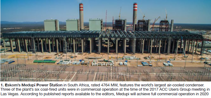
Ockert Augustyn, Eskom, Johannesburg, SA, returned in 2017 to discuss the operating performance—particularly during windy conditions—of the world’s largest ACC at Medupi Power Station. Medupi has six 794-MW coal-fired units; three were operating at the time of the meeting (Fig 1).
Eskom, which produces about 95% of South Africa’s electricity, operates large ACCs at four multi-unit installations. Fans measuring 30 ft in diameter number between 48 and 64 per condenser; platform heights are 145 to 195 ft. Water restrictions dictate use of ACCs.
Augustyn stressed that all ACC performance requirements are specified by the purchaser; the supplier is responsible for compliance and design. However, repeating the message from 2012, the supplier can be at an advantage because performance testing is not conducted at high-wind conditions.
He then outlined the risks for the purchaser (Eskom). A supplier could be reluctant to add safety margins or other features that would render their offering less competitive, and the purchaser may not be able to disqualify offers or justify higher costs if all suppliers meet the specification. More important, performance characteristics in windy conditions are essentially unknown until after commissioning (too late for design changes).
Because most suppliers are in compliance with specifications, the advantage is theirs, and the purchaser needs to be knowledgeable of all potential risks and limitations.
Operational experience for Eskom shows significant capacity loss during adverse weather conditions (high temperature and high wind speed, in particular). At the older Matimba site, CODs of its six 665-MW units extended from 1988 to 1993 (Fig 2); 12 vacuum-related unit trips attributed to wind occurred during the first 7 years of operation. In 2016 alone, there were multiple cases of load losses exceeding 1000 MW.
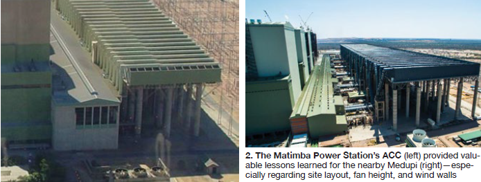
Planning for Medupi drew upon Eskom’s experience at Matimba and other plants:
- Atmospheric conditions were based on 130-ft elevation above grade.
- Design wind speed was 20 mph in any direction.
- Wind wall height was extended to the top of the steam duct.
- An 8-ft-wide solid walkway was placed around the entire platform perimeter (for maintenance work, but also to reduce hot air recirculation).
- Wind cross on ground level was 33% of fan inlet height.
- Performance guarantees were verified by CFD before construction.
Also required was an increased gap (165 ft) between the ACC and turbine building (compare Figs 1 and 2).
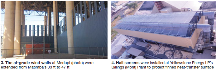
The at-grade wind walls at Medupi were extended from Matimba’s 33 ft to 47 ft (Fig 3).
Augustyn explained: “We went with what we knew, then made things stronger and bigger.”
Medupi entered commercial operation in October 2015 and has experienced no vacuum-related load losses. ACC performance comparisons of Medupi and Matimba benefit from proximity of the two plants. Eskom representatives would return later in the meeting.
Hailstorms
Moving away from South African heat, Dan Burns, Burns Engineering Services (Minnetonka, Minn) presented “Protecting an air-cooled condenser from hail damage,” referencing a patent-pending system at the Yellowstone Power Plant in Billings, Mont.
Yellowstone is a two-unit coke-fired plant with an ACC commissioned in 1995 having two streets and 10 cells.
A major hailstorm hit the area on May 18, 2014, with hail up to 2.5 in. diameter. Severe damage occurred to the finned surface areas. Dented fins restrict air flow and thus reduce heat- exchange capability.
The protective material selected was standard SS316L metal wire screen, tensioned over a support structure (Fig 4). Screens were placed above the steam distribution duct at 75 ft above grade and on the perimeter.
Discussion topics included material options, angle of hail attack, cost, and opening size versus hail buildup.
Dynamic response
Danie Els of South Africa’s Stellenbosch University, presented “Dynamic response of ACC fans,” describing precise details of onsite measurements for blade and shaft loading, laboratory analysis of vibration sources, and simulations of fan-system dynamics (response versus design).
Els began by explaining distorted inlet airflow conditions caused both by winds and the influence of other fans, as well as common downstream flow obstructions (Fig 5).
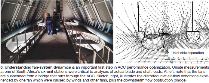
He followed with blade-loading measurement details including fan location within the ACC and spatial relationship to boiler and generator hall, followed by wind speed, wind direction, and vibration frequencies. Laboratory analysis looked at the effect of the fan bridge on fan-blade vibration, using variables of flow rate, distance between fan rotor and bridge, and bridge solidity.
Details of shaft bending versus wind direction followed. Matimba was used as a reference plant.
Wind screen design by CFD
Cosimo Bianchini, a CFD specialist at Italy’s Ergon Research had participated in 2016 by video link from Italy. He was on location in Las Vegas to enhance both detail and discussion on CFD modeling of wind screens.
His presentation “CFD analysis for optimal wind-screen positioning” began with the basics: powerplant performance can be affected by wind’s impact on the ACC, reducing net power by 10% or more for each 22 mph of wind.
Two common sources of wind-induced ACC losses are fan performance degradation and recirculation of hot air into downwind fan inlets.
Bianchini outlined the overall modeling strategy:
- Reproduce the 3D local air field around the ACC using CFD.
- To maintain computational costs within reason, do the following:
- Assume constant wind magnitude and direction.
- Assume other plant systems operate at nominal conditions.
- Include active CFD sub-modules for fans, heat exchangers, and wind screens.
The test case presented was an ACC of five streets (eight fans each) partially surrounded by tanks and buildings. Fan diameter was 38 ft, deck elevation 65 ft.
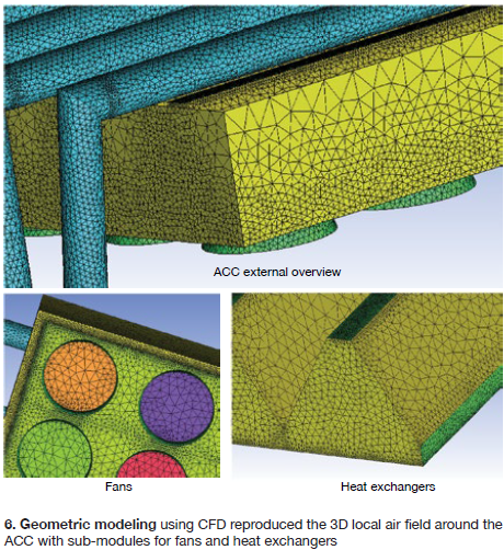
Geometric modeling (Fig 6) used an unstructured hybrid grid (total of 10,000 cells):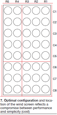
- Tetrahedral elements were used to model the free-stream.
- Prismatic cells were used to better define the boundary layer.
- Many solid walls were treated as thin surfaces:
- Most ACC walls are solid.
- Fan and bundle surfaces (fan model and radiator model).
- Wind screens and lifting devices (pressure-jump model).
One advantage of modeling is the ability to test variations. In this case, 11 mitigation devices (screen plans) were tested by combining various suspended and ground designs. The optimal configuration, a compromise between performance and cost, was the cruciform fabric screen (30% open area) and suspended vertical screens around the ACC walls (Fig 7).
The conclusions: wind screens can mitigate wind losses, showing a gain of up to 14% at 22 mph. This recovery factor starts decreasing at intermediate wind speeds. Actual flow rate depends on wind-screen configuration, wind speed, and wind direction.
Chemistry and corrosion
Barry Dooley launched the second day with an update on cycle chemistry and flow-accelerated corrosion (FAC) damage, offering a world view for all ACC designs and all chemistries. Last year the presentation highlighted inspection, and understanding the resulting data.
Dooley, a member of the steering committee, again stressed that the relationship between total iron and pH is consistent worldwide, and corrosion results in elevated iron levels. High concentrations of iron within the cycle lead to HRSG deposits (and expensive chemical cleaning), tube failures (including overheating), and potentially steam-turbine deposits. He repeated, “Overall, an ACC controls unit cycle chemistry.”
He reviewed the Dooley/Howell Air-Cooled Condenser Corrosion Index (DHACI) with specific visual examples. (See section on Comanche 3 below.)
Dooley stressed the importance of investigating for “holes in the tubing or welding” at tube entries.
He then offered a list and status of current solutions for FAC:
- Increase bulk condensate pH up to 9.8 with ammonia: Effectiveness has been validated.
- Increase local pH with neutralizing amines: Appears effective.
- Add film-forming products: Appears to work but science is incomplete.
- Use filters and condensate polishers: Can lower iron transport but does not stop FAC.
- Add coatings, sleeves, inserts: Insufficient information.
- Convert to alternative materials: Rare, no validation.
- Change the design: Designs vary, but FAC still occurs.
He also stressed that, even with proper chemistry changes, damage takes time to repair (using examples of 18 and 24 months).
Dooley ended with a complete review of Technical Guidance Documents available for fossil-fired steam and combined-cycle plants available free of charge through iapws.org. His final thoughts:
- 1. Increasing condensate pH to 9.8 gradually eliminates the FAC damage at the tube entries and iron levels will reduce to IAPWS-suggested levels of 5 to 10 ppb.
- 2. Damage on cross members is not repaired as quickly by increasing pH because the mechanism of metal loss appears to be different.
ACC corrosion
Bill Stroman, KAAM Group Inc, Carlsbad, Calif, followed Dooley with “Chemistry options to address FAC-like corrosion.” The subject was two identical ACC-equipped 1 × 1 combined cycles. Because of “the cost of scaffolding,” the upper ducts had not been inspected since commissioning (11 years).
At present, Unit A operates intermittently; Unit B is primarily baseload but beginning to cycle. During a recent inspection, FAC-like corrosion was noted in the upper ducts and transition duct.
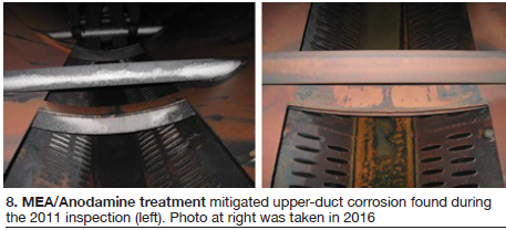
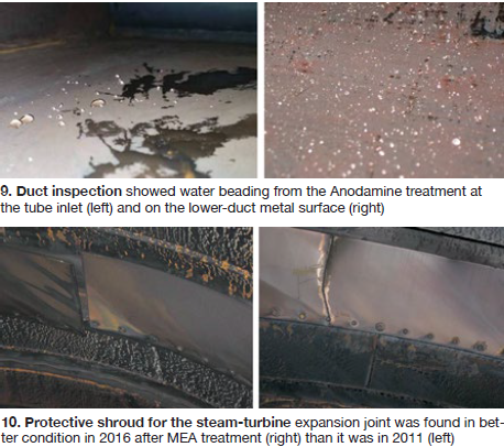
Based on experience with other generating stations, Plant A operators switched to MEA (monoethanolamine) treatment in 2012, then due to cycling switched to an MEA/Anodamine filming program in 2013 (to improve offline protection). ACC upper duct inspection showed improvements (Fig 8) after the change. Inlet vanes showed similar improvement. Duct inspection also showed water beading (hydrophobicity) from the Anodamine treatment (Fig 9).
Plant B also showed ACC improvements although it remained with the ammonia MEA treatment program. One significant improvement was the steam turbine expansion joint protective shroud (Fig 10).
Comanche 3 hybrid
Andy Howell, Electric Power Research Institute, and chairman, ACC Users Group, presented a seven-year status report of the ACC in the hybrid wet/dry cooling system at Xcel’s Comanche Station Unit 3. The 750-MW supercritical coal-fired unit began commercial operation in 2010.
System pH has been maintained between 9.45 and 9.60 with ammonium hydroxide; iron is less than 0.3 ppb at the economizer inlet and 1 to 3 ppb at the high-pressure heater drain. Internal ACC inspections were conducted at 14, 50, and 81 months.
The presentation provided a valuable backgrounder on the Dooley-Howell ACC Corrosion Index rating system and ACC.01, “Guidelines for internal inspection of air-cooled condensers” developed by the ACC Users Group and available at www.acc-usersgroup.org/reports/.
Conclusions for this presentation were:
- ACC tube inlet corrosion has been inconsistent while steam-cycle chemistry has appeared to be consistent, and
- Options for evaluating tube corrosion, such as thickness testing and corrosion coupons, have been implemented at Comanche 3 and may prove useful.
Gearbox design
Chad Brown, engineering manager, Amarillo Gear Co, Amarillo, Tex, discussed “Reliability in an ACC gearbox: from a designer’s perspective.” His agenda covered standards, application considerations, and serviceability.
Brown began with the written standards, developed in a consensus-based process to clearly describe required characteristics. Such standards set the baselines, promote efficiency and quality, and safeguard people and equipment.
Among the standards discussed were those endorsed by the American Gear Manufacturers Assn (AGMA), International Organization for Standardization (ISO), and German Institute for Standardization (DIN).
“One key,” stated Brown, “is to know that there are differences, and that one standard is not necessarily better or worse than the other. But it is important to understand the variances.” In one example, he listed an AGMA example as “empirical, based on experience” and the ISO counterpart as “theoretical, based on academia.”
He then offered an in-depth look into CTI Standard-167, “Gear speed reducers for application on air-cooled condensers,” issued in 2017 by the Cooling Technology Institute.
Brown was not promoting his company; he was promoting quality and standards. His conclusions:
- 1. Understand the hierarchy of standards to your advantage when designing and selecting a gearbox for air-cooled condenser use. Remember: Different standards yield different results.
- 2. CTI STD-167 should be used to provide the highest reliability in an ACC application. It “levels the playing field,” suggested Brown.
- 3. ACC gearboxes face unique challenges that need to be understood and addressed by the owner/operator, plant engineer/constructor, ACC OEM, and gearbox manufacturer to ensure maximum reliability.
Gearboxes in South Africa
Augustyn returned to discuss Eskom’s 20 years of gearbox experience in the large South African units. Within its ACC fleet, Eskom has various gearbox configurations with a wide range of problems, remedies, and alternatives.
The utility operates nine different types of gearboxes from three manufacturers. Its gearbox population exceeds 1200.
Casing types are both mono and split. Lubrication is both splash and force-feed. Oil is both mineral and synthetic. Fan bridge layouts differ.
An interesting note was a plan to leave grating open space (around the gearbox) for maintenance. His point: “If you are 190 ft above grade, it’s 115F ambient, and you ask someone to temporarily remove some grating, it probably won’t be put back.”
Eskom is also considering direct-drive gearboxes (the industry’s first is now operational at Dry Fork Station in Wyoming).
Gearboxes at Tracy
Sean Berryman, maintenance manager, followed with a review of gearbox experience at NV Energy’s Frank A Tracy Generating Station. The plant’s 2 × 1 F-class combined cycle is a 541-MW load-following unit operating at 96% equivalent availability and providing 35% of Northern Nevada’s energy needs. This includes an ACC with 30 fans arranged in six streets. Fans are rated at 250 hp, and gearboxes at 500 hp. All fans are required during summer operation.
Historical gearbox failure has been 15% to 25% (2011 to 2017).
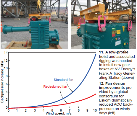
Moving forward, 20 new 750-hp gearboxes will be installed. This will require larger hoists (3 tons versus 2) and low-profile hoist/rigging to lift the new boxes over the motors (Fig 11).
As an aid to not only maintenance time but to employees, a rack-and pinion-elevator has been installed. Another site innovation is online oil filtering of gearbox sumps using a hand-held, operator-friendly system.
Tube cleaning
Romain Pennel, a director at AX Systems, Bailleul, France, presented on a cleaning system created in France in 2008 by Miroslaw Glusko.
Pennel began with an overview of fouling mechanisms, showing how they create an isolation film and limit air flow through the fins, thereby reducing heat transfer. This includes fouling from the natural environment (such as pollen or sand) and from industrial sources (fiber, dust, and oil). The result: Reductions in vacuum, turbine steam flow, and power generation.
ACC configurations covered in the presenter’s discussion of cleaning systems and challenges included flat, A-frame and V-frame.
Examples of what not to do with regard to external cleaning of heat-transfer surfaces included the following:
- Don’t use manual high-pressure spray equipment: It’s easy to bend fins when the spray head is not perpendicular to the tube surface.
- Avoid sandblasting. Risks include fin damage and removal of any tube coating—aluminum, for example.
- Say “no” to use of a bicarbonate solution for cleaning. Risk is the electrolysis effect between aluminum and NaHCO3
A case study was presented on a 29-MW waste-to-energy plant in the UK, commissioned in 2014 with two A-frame ACCs. Power had dropped to 26 MW and vacuum to 0.7 bar, suggesting the need for cleaning. Post-cleaning results showed vacuum at 0.9 bar and power at 28.29 MW.
Tube-cleaning document
Andy Howell followed with a status on the planned ACC Users Group document ACC.02, “Finned tube heat exchanger tube cleaning.” The current outline for the document is below.
- Operational factors limiting ACC efficiency.
- Ambient temperature.
- External tube fouling.
- Foulant removal.
- Water.
- Air.
- Carbon dioxide (dry ice) pellets.
- Frequency of finned-tube cleaning.
- Implementing the cleaning process.
- Tubing structural/operational inefficiency issues.
- Safety and environmental.
- Conclusions
- References
All participants (and CCJ subscribers) are invited and encouraged to participate with suggestions, reviews, and comments.
Ultra-efficient fan design
Participants returned again to the Matimba ACC in South Africa. At the time of construction, this unit was the largest ACC in operation anywhere in the world (3690 MW in 2001). Eskom has firmly established itself as a “world leader in dry-cooling technology.”
The plant has also suffered historic losses, specifically in windy months. But it is not economically feasible to reduce load losses entirely. Typical annual production is 24,000 GWh. Vacuum-related losses in 2016 were 350,000 MWh, or less than 1.5% of total production. “Economics make it difficult to find a solution that justifies the capital expenditure without the guarantee of total load-loss reduction,” explained Augustyn.
Eskom conducted a thorough review of previous CFD work, including placement of wind screens. This led to a detailed review of fan performance.
Aerodynamic design was reviewed with CFD, keeping the same duty point. Static efficiency was set at 60%, and a steep curve was established to protect against wind. Stellenbosch Univ became involved. A consortium was established to design, manufacture, install and commission a 30-ft-diam fan. Consortium members included Kelvion (Germany), Enexio (Germany), ECILIMP Termosolar (Spain), Soltigua™ (Italy), IRESEN (Morocco), Waterleau Group NV (Netherlands), and Notus Fan Engineering (South Africa).
A unique manufacturing process offered consistent weight distribution and a repeatable infusion process. When eight blades were weight-tested, there was only a 500-g difference (less than 1%). There also was a 50% weight reduction with the new design.
Blade angle settings achieved increased volume flow and reduced fan power consumption.
A striking benefit was improvement in turbine backpressure vs. wind speed (Fig 12).
Aerodynamic improvements:
- New fan consumes 15% to 20% less power for similar flow displacement.
- Volume flow rates can be increased by 10% to 20%.
- Cells have greater protection against wind effects.
Structural improvements:
- Blades are not resonating (vibrational loads on gearbox greatly reduced).
- Fan blade weight is reduced by 50%.
- Blade shape and structure are consistent (interchangeable blades).
Funding was provided by the European Union through its Horizon 2020 Research and Innovation Program.
Air in-leakage
Oscar Hernandez, InterGen, a member of the steering committee, offered details on air in-leakage at three ACCs in Mexico and two in the UK.
At one plant in Mexico, accurate online instrumentation detected a change in dissolved oxygen concentration leading to repair of a spray nozzle. In another, dissolved oxygen again triggered an investigation leading to a steam-turbine gland seal out of position. For both, credit was given to accurate online instrumentation and continuous chemistry monitoring.
A lengthy list of key indicators beyond chemical parameters was reviewed, highlighting such items as increase in backpressure, decrease in condensate temperature, and loss of ACC vacuum. This was followed by a list of common air in-leakage sources including missing hardware, penetrations, welds, turbine shaft seals, expansion joints, pump seals, manways, and valves. Thermal imaging was recommended, looking for black spots.
IAPWS is reviewing the subject of air in-leakage for a new Technical Guidance Document planned for 2018.
Ivanpah and Higgins
On the final day, participants were offered tours of two facilities: the Ivanpah Solar Thermal Plant and the 2 × 1 combined cycle Walter M Higgins Generating Station.
Kristen Pogozelski, who is leading optimization efforts for Ivanpah’s liquid ring vacuum pumps (LRVPs), addressed the participants on Day One.
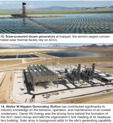
Each of the three solar thermal steam generators at Ivanpah (Fig 13) has a three-street ACC with five fans per street. The facility was commissioned in 2013.
Units have been showing reduced vacuum, impacting megawatt production. Helium testing found leaks in the main boiler feed pumps, turbine bearing gland, steam supply line, and at several areas in the vacuum pump skids. The main target became the liquid ring vacuum pumps.
Laura Sterk, NRG Energy, gave an overview of Ivanpah to orient attendees for the plant tour.
At Higgins (Fig 14), the summer peak is about 530 MW. Operational since 2004, the plant has continually performed in the top 10% of combined-cycle plants in the US with a 99% availability, according to NV Energy’s Dave Rettke, NV Energy, a member of the ACCUG steering committee. Rettke conducted the tour.
Dry cooling enables Higgins to make the same amount of electricity with only 7% of the water used by a comparable conventional water-cooled facility. The plant’s ACC has eight streets, each with five 30-ft-diam fans.
Inspection and maintenance are keys to success at Higgins. The site conducts thorough weekly walkdowns of all equipment, recording all observations. As Rettke explained, “It’s important to see an ACC as a live structure under the influences of wind, vibration, and thermal changes.”
Many unique procedures and tools have been developed by Higgins personnel. Ongoing vigilant observation by site personnel has allowed the plant to maintain high availability, even while it has moved from base-load to cycling operation. CCJ