 With the 2023 Combined Cycle Users Group (CCUG) approaching August 28-31 in Atlanta, part of the greater Power Users Combined Conference, reviewing some of the content from last year’s meeting should encourage you to attend or send someone from your organization to experience this valuable content in person. Presentation abstracts below are based on information available only to end users in the slide decks posted at www.powerusers.org. Those seeking deeper dives into specific topics should note the presentation titles in italics at the end of each summary and access the source material on the website.
A fresh approach to safety
No one argues that safety is paramount in industrial work spaces. However, some safety programs are demonstrably more successful than others. MD&A’s Matt Barnes gave the CCUG audience the benefit of his company’s program focused on (1) positives rather than negatives, (2) people as the solution and not the problem which has to be controlled, and (3) safety as an ethical responsibility, not bureaucratic accountability to the higher-ups. The results he presents are worth a look.
These four simple principles anchor the effort:
- Focus on a few things that really matter and do them well.
- Push organization learning and risk reduction more than compliance.
- Tell employees “what to do” less, “what they need” more.
- Focus on and measure the capacity to work safely.
Remediate, rather than replace, turbine oil
Recent test results suggest, according to John Hayes, Lubrication Engineers Inc, that sites with turbines experiencing lost demulsibility and other degradation factors of Group I and II lubricating oils can remediate it by displacing the original volume of oil with Group I oil at 5-20%, rather than completely replacing it or using expensive additives. Other slides comprise a quick tutorial on types of lubricating oils and performance impacts from degraded oil.
“Group 1 Turbine Oil, A Return to Reliability”
Is your CO catalyst impairing your NOₓ catalyst during turndown?
NO₂/NOₓ ratios higher than 50% lower catalyst performance, high NO₂ levels are typical during load turndown and startups, and CO catalyst can increase the NO₂/NOₓ ratio by converting NO to NO₂. Andy Toback, Environex Inc, uses two case studies to show how NO₂ levels change with load and fired or unfired HRSG conditions. Conclusion is that CO catalysts designed for high VOC (volatile organic compounds) conversion, attributed to conservative design VOC levels submitted by turbine suppliers, exacerbate the NO₂/NOₓ levels. However, some catalyst formulations are available which convert less of the NO to NO₂.
“Is Your SCR/CO System Ready for Turndown?”
High-energy piping now requires more ‘energy’ from users
The 2007 ASME B31.1, addressing high-energy piping systems, was updated in 2020 and includes more detail and entirely new sections, written O&M procedures, and requirements for documenting operating hours, modes of operation, temperatures, pressures, transients, and much more, observes Amy Sieben, I.A.F.D. Sites also need to record weld examinations, hanger inspections, and NDE inspection results. Piping upstream and downstream of attemperators should also be included because “it is the most highly fatigued piping in the entire plant.” If you are still working off of the 2007 version of the code, Sieben’s slides are a must-view.
“B31.1 Covered Piping Systems Requirements and Hanger Inspections”
 With the 2023 Steam Turbine Users Group (STUG) approaching August 28-31 in Atlanta, part of the greater Power Users Combined Conference, reviewing some of the content from last year’s meeting should encourage you to attend or send someone from your organization to experience this valuable content in person. Presentation abstracts below are based on information available only to end users in the slide decks posted at www.powerusers.org. Those seeking deeper dives into specific topics should note the presentation titles in italics at the end of each summary and access the source material on the website.
Major outages: Plan the work, work the plan
The best way to minimize outage time is to create a detailed, long-term maintenance plan for the unit, and an experienced turbine services firm can help. Tim Keen and Neil Jones, MD&A, take you through the obvious, like scope, schedule, and budget, but also overlooked factors like special tooling that may be required, structural steam-path audits, comparing clearances to those taken at the last outage, casing horizontal joint gaps and diameter out of roundness, valve operation, and coupling alignment.
“Outage Planning Focused on the First/Second/Third Majors”
Address past ‘pain points’ in future bid specs
The first 12 slides in this “big picture” presentation by Eric Prescott, EPRI, address the general industry landscape for future capacity options (more specifically, renewables) driving the need for flexible, dispatchable combined cycles, and the impacts on steam turbine/generators (ST/G). However, the meat of the message is how to incorporate experience with ST/G damage mechanisms into bid specifications.
Balance of the slides are a glimpse into the publicly available EPRI report (No. 1024903), “QA/QC Practices for the Procurement of Steam Turbine and Generator Equipment.”
Heavy outage season—a tale of two vendors
The pride and joy of STUG are presentations like this one, in which a user with responsibility for dozens of ST/Gs in his company’s fleet dispassionately describes experience with two different vendors, not to throw shade but to work out how both vendor and user can improve the experience. One vendor was contracted for major outage work on two HP/IP turbines at different sites, the other for packing/seal replacements on two D11 units (from different suppliers) at different sites. The slides include a blow-by-blow account of how the work transpired and the all-important lessons learned. Among the major ones:
- Insist on early data review between user and vendor before the manufacturing of packing rows begins.
- Do not allow packing to be final-machined until opening data have been fully reviewed and the rebuild strategy for the machine is defined.
- Best practice is to send a segment from each row to the packing vendor for reverse engineering.
But don’t deprive yourself of the details supporting these and other recommendations, especially if you are or will be soon undertaking the first major for an ST/G (the situation for two of the units described here).
“Vendor Shop/Field Considerations During a Heavy Outage Season”
Watch this varnish vanish
If you are having issues with varnish in your lube or control oil systems, or if you never thought varnish was that important, then Axel Wegner’s (C C Jensen, Oil Maintenance) slide deck is for you. It serves as a quick primer on the topic, beginning with the claim that the company’s “varnish removal unit,” or VRU, is the safest and most efficient technology for dealing with the troublesome byproduct of circulating oil systems at elevated temperatures. Prevention through oil changes and bleed-and-feed strategies are only half the story.
C C Jensen’s VRU is described as a depth-filter absorption/adsorption process with advanced agglomeration, which can remove both soluble and insoluble varnish. Wegner also extols the benefits of online oil condition monitoring.
Sadly, Axel Wegner passed on May 5 (2023) at age 55. RIP.
 With the 2023 Generator Users Group (GUG) approaching August 28-31 in Atlanta, part of the greater Power Users Combined Conference, reviewing some of the content from last year’s meeting should encourage you to attend or send someone from your organization to experience this valuable content in person. Presentation abstracts below are based on information available only to end users in the slide decks posted at www.powerusers.org. Those seeking deeper dives into specific topics should note the presentation titles in italics at the end of each summary and access the source material on the website.
Meaningful stats help guide improvement in plant performance
Equipment quality and personnel safety are top of mind at user-group meetings. The first presentation after lunch on Day One is valuable for the guidance it offers regarding generator components and processes to focus on at your plant to maintain top performance. The owner/operator’s database of regulated and unregulated assets is extensive: 227 non-hydro generators representing 48 different models from nine OEMs.
Stator windings are at the top of the “failing equipment” category with issues affecting 20% of the total fleet. Stator cooling water was next at 13%, followed by isophase bus/flex links and the rotor, each 10%. Brush rigging came in at 7%, seal-oil system at 6%, and AVR, exciter, and stator core each at 5%.
Process shortcomings were most evident in vendor execution, 24%; PM scope/inadequate frequency, 22%; and inadequate process/procedure, 14%. Installation error was next at 10%, with OEM design deficiency right behind at 8%.
Causes of poor quality identified included loss of vendor experience, substandard planning, poor procedures, complacency, lack of training, etc. Human performance tools that could have prevented many of the issues were better procedures and adherence to them, more positive attitude, when to stop work when problems arise, pre-job briefing that includes the consequences of incorrect actions.
The presentation can help you develop a better vendor qualification process, improve your procurement specifications, provide more effective vendor oversight, and improve vendor accountability.
Solutions for condensation in metal-enclosed bus ducts
“Metal-enclosed bus ducts should be part of your regular preventive maintenance program,” began Mohsen Tarassoly, EBI (Electrical Builders Inc), “but half of your issues will stem from condensation or water intrusion.” Designs for bus enclosures haven’t changed since the 1990s, but welded and bolted designs are more susceptible to moisture. None of the designs account for the frequent cycling these busses are exposed to, aggravating the situation.
The heart of the presentation focused on solutions, including drain plugs, isolated phase bus (IPB) insulator heaters, strip heaters, dry air systems, forced-air cooling systems, gel packs, and dessicants. Some of these impose their own maintenance concerns, he cautioned. During the Q&A, one audience member suggested that you turn on your forced-air system for several hours before starting the unit, especially in humid climates like Florida.
“Anti-Condensation Measures for Metal-Enclosed Bus What You Need to Know”
Hydrogen, the preferred cooling medium for large generators, demands respect
Hydrogen must be purged from generators prior to entry or exposure to air to prevent fire or explosion, which can occur with minimal ignition energy. Recall that the lower explosive limit for hydrogen in air is 4%. The upper explosive limit is 76%.
For maintenance, the inert gas of choice for purging hydrogen is CO₂, followed by an air purge. Once maintenance is complete another purge is needed to remove the air prior to recharging with H₂. In emergencies—such as fire, loss of shaft seal, low H₂ purity (less than 92%)—the generator is flooded with CO₂.
Andrew Slaugh, senior applications engineer for Airgas, told attendees that the traditional method of using CO₂ from cylinders for purging can be challenging. For example, it can take several people to monitor and maintain the purge flow: There can be interruptions in purge flow because of dry-ice formation, empty cylinders, change-out of cylinders, etc. Plus, it can take many hours to complete the purge.
An alternative is Airgas’ TurbinAL purge system which is said to provide uninterrupted gas flow at all times with no operator actions and with no power required for purging—as well as other benefits.
Presentation is valuable for its review of the fundamentals of safe hydrogen purging. It is recommended reading for anyone involved with hydrogen filling and removal.
“Implementation of a Reliable CO₂ Purge System”
Troubleshooting with EMSA
Cutsforth’s presentation offers some good observations on approaches to effective troubleshooting. The case study profiled, in progress, using Electromagnetic Signature Analysis, revealed increased activity in the 30 Hz to 100 MHz band, which typically indicates an issue with the isophase bus duct. However, the problem could be external to the bus duct—such as with the GSU or another non-generation-related source.
The continuously elevated EMSA level indicates that the source is not cyclical in nature—such as plant lighting. Next step likely would be to get the utility’s generator engineering group involved in the analysis. Stay tuned.
 With the 2023 Power Plant Controls Users Group (PPCUG) approaching August 28-31 in Atlanta, part of the greater Power Users Combined Conference, reviewing some of the content from last year’s meeting should encourage you to attend or send someone from your organization to experience this valuable content in person. Presentation abstracts below are based on information available only to end users in the slide decks posted at www.powerusers.org. Those seeking deeper dives into specific topics should note the presentation titles in italics at the end of each summary and access the source material on the website.
Build a Mark VIe controller
If you’d like to learn how to build a controller for the Mark VIe control system, select variables and constants, add logic, change setpoints, and use the configuration, then these two sets of slides with get you familiar with the screens involved. The second training “lab” focuses on trip logs, historical data collection, and the PI historian.
No historian? No problem
These user-provided slides show you how to “look at high-speed historical data from your GE Mark VI or VIe even if you don’t have a GE historian.” GE ControlST software, in an area called WorkstationST, has a feature called “Recorder” which has many of the same functions as a historian. In particular, the presenter drills down to explain how to set up the “continuous collection” feature of “Live Data Collection,” and offers two methods for viewing the data.
“GE Controls ST Data Collection Tools”
Extract more value from PI
The seasoned PI administrator for a large fleet gives tips for extracting more value from your data historian, particularly in the areas of getting better data (compression and exception functions), improving analytics, and facilitating reporting. A real-world example of almost draining a chemical tank and suffering equipment damage illustrates some of the points.
“Making the Most of your PI Historian”
How to be an effective owner’s engineer
Abel Rochwarger, GTC Control Solutions, a division of AP4 Group, offers lessons learned from controls upgrades of two gas turbines. Findings include mislocation of power supplies, errors in drawings, and missing SCR fault-detection coils. The mission, he says, of an owner’s engineer is to avoid conflict and deliver good service.
AGT Services Inc’s Jamie Clark frequently is asked to present at user group meetings given his deep knowledge of generators. At last year’s (2022) Frame 5 Users Group conference, Clark conducted a well-received workshop on generator testing, inspection, and condition assessment which is of value to most participants in the Legacy Turbine Users Group—owner/operators of Frame 5, 6B, and 7B-EA GE engines.
If you did not participate in that workshop, the editors suggest a review of the 130-slide deck posted at www.powerusers.org. It contains scores of excellent photos/illustrations, many especially valuable to users who haven’t yet participated in a generator major. Jot down questions during your review and visit with Clark at the vendor fair accompanying this year’s meeting, July 17-20, in the Sheraton Grand at Wild Horse Pass (near Phoenix). He’s sure to welcome the discussion.
Stator
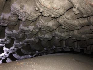
Roughly 80% of the slides Clark created for the workshop pertain to the stator (winding, endwinding support system, wedge system, and core iron); the remainder, the field (rotor). He began his presentation by stressing the need for good reference material, suggesting that IEEE 62.2, “Guide for Diagnostic Field Testing of Electric Power Apparatus—Electrical Machinery” be within arm’s reach.
Complete all visual inspections prior to cleaning stator components, Clark said, but clean them prior to electrical testing, that step being important to achieve accurate test results. Your inspection goals should be to identify detrimental deterioration/conditions, compare results to history, and apply intelligent and timely corrective actions.
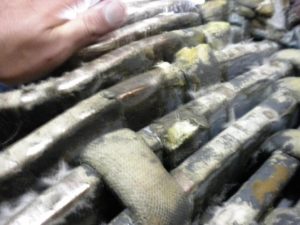
With regard to the stator winding, inspect for contamination (Fig 1), loose or broken ties (Fig 2), cracked paint, loose blocking, tape separation, corona activity (Fig 3), and global movement. In the endwinding support system check behind the winding for hardware looseness and felt supports. Note that loose or broken ties should be repaired to protect against endwinding motion and vibration.
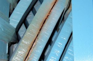
Core maintenance issues to be aware of include tightness, interlaminar insulation degradation, mechanical damage and lamination migration. Precursors of problems include iron oxide on the back of the core and on wedges. A simple knife test is a good way to assure tightness (Fig 4).

Damage to laminations may be smeared tooth tips, bending, overheating (Fig 5), burn spots. Core iron should be checked for migration in the outside space blocks (OSSB). Next check the first three rows of inside space block on each end for migration.
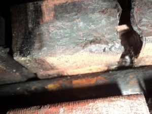
Important to conduct a wedge survey and to record the condition of the wedge system. Create a map that identifies the loose wedges and their locations.
At the end of the stator portion of his presentation, Clark recommended the following dc tests be conducted at a minimum:
- Phase (winding) resistance.
- 5- or 5-kV insulation resistance (Megger) and Polarization Index (a/k/a PI).
- Dc leakage.
- Power factor/Doble test.
- High-potential (HiPot).
- RTD resistance and Megger.
- El Cid.
Rotor (field)
Key elements of a visual inspection of the field, Clark said, are the following:
- Overall assessment of condition regarding dirt, oil, and other contaminants. Fields can get very dirty, Clark reminded the group, and stressed the need for cleaning before testing. To illustrate the impact of dirt on electrical readings he shared test results on one project that revealed 17,300 ohms before cleaning and 5850 megohms after steam cleaning.
- Look for arcing between wedges and in the wedge-to-retaining ring area.
- Note any hot spots on tooth tips at wedge joints.
- Examine retaining rings for condition; consider looking under the rings using a borescope (Fig 6).
- Verify collector ring is in good condition.
- Check for fan damage.
- Look closely for copper dusting.
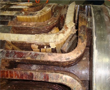
Retaining rings typically are very reliable, especially those made of 18/18 alloy. Going beyond a visual inspection is suggested if pitting, cracks, and arc marks are found. If the rings are magnetic, mag particle testing would be the first step. If 18/18, the best results are produced with a combination of UT and eddy-current testing. The former is good for finding deep inclusions, the latter for identifying surface problems. Liquid-penetrant or Zyglo is another option if there are no deep inclusions.
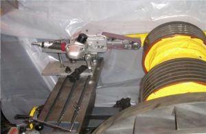
Collector rings can suffer from worn surfaces, foreign object damage, and ghosting or foot-printing. The first generally can be corrected easily by removing some metal from the rings (Fig 7, 10 mils is typical).
Collector rings should be HiPot-tested with the field during rewinds. Note that a standard test and inspect will not include a HiPot of field components. If collectors are separated from the field winding they should be HiPot-tested individually after a good Megger test.
Recall that a good Megger indicates dry winding, low contamination, and good insulation. By contrast, a poor Megger indicates possible contamination, bad insulation, or a wet winding. If you are challenged by a low Megger, clean the collector rings and retest. If still low, separate the collectors and retest. If still low, tent the field and use heat and dehumidifiers to dry. Finally, if not much progress after several days, consider removing the retaining rings and doing an internal cleaning.
Other field electrical tests:
- Ac impedance test. Increase ac voltage from 0 to 130 V in 10-volt increments. Plot an impedance curve measuring ac volts and amps and look for step changes in the curve, which could indicate shorted turns. No step change indicates no shorted turns in static condition.
- Winding resistance. Be sure to correct to 25C and check results against the factory-issued resistance for your field as well as against previous test results. A decrease in resistance indicates possible shorted turns, a higher resistance broken connections/loose studs.
- Pole balance test. Apply a voltage across the collector rings and measure from one ring to the pole jumper, then the other. Rule of thumb: Measured voltages should be with 5% of each other. The challenge in conducting this test is to reach under the retaining ring and to put a test lead on the pole jumper.

The Frame 6B Users Group’s 2023 Conference and Vendor Fair is only six weeks away, July 17-20, in the Sheraton Grand at Wild Horse Pass (near Phoenix). The meeting is co-located with the annual conferences of the Frame 5 and 7EA Users Groups, all three organizations coming together for meals and the exhibition. Collectively, the groups are known as the Legacy Turbine Users Group.
The Frame 6B program (regular updates at www.powerusers.org) is similar in many respects to the agendas of other organizations serving gas-turbine owner/operators. For example, it features user and vendor presentations as well as deep dives into topics the steering committee has asked the OEM, GE in this case, to present on. But what the 6B group does especially well, in the minds of the editors, is its hour-long roundtables dedicated to safety, auxiliaries, air inlet, compressor, combustion section, turbine, I&C, and generators.
These open-discussion sessions, led by members of the steering committee having deep experience with this frame, are designed to deliver the O&M and design information you need to do the best job possible in running your facility.
However, you cannot maximize the value of participation without investing some pre-conference time thinking about what you’d like to learn/better understand from your colleagues during the user-only roundtables. Bring those notes to Phoenix along with relevant documentation, photos, etc. The more detail you can provide attendees during these sessions the more valuable will be their assistance. Think of this as free consulting.
A checklist of possible discussion topics for each of the roundtables follows. These are intended simply as a guide; your interests likely are far more specific and will be a catalyst for meaningful discussion.
- Fire suppression systems—Halon, CO₂, water mist, heat detectors.
- Hazardous gas analyzers.
- Lock out/tag out.
- Confined space entry—turbine compartment, inlet-air filter house.
- Safety equipment.
- Starters.
- Torque converter.
- Clutch.
- Ratchet system.
- Accessory and load gears.
- Lube and hydraulic oils.
- Oil-mist separator.
- Cooling/ventilation.
- Filter house layouts.
- Drift eliminators.
- Filters.
- Pulse cleaning.
- Inlet conditioning—evaporative cooling, fogging, chiller, wet compression, inlet bleed heat.
- Ductwork.
- Silencer.
- Trash screen.
- Bellmouth.
- Inlet guide vanes.
- Rotor.
- Stator.
- Extractions at fifth, eleventh, thirteenth, sixteenth, and seventeenth stages.
- Exit guide vanes.
- Compressor efficiency and how to calculate it.
- Washing online and offline.
- Fuel nozzles—testing, calibration, repair.
- Liners.
- Flow sleeves.
- Transition pieces.
- Crossfire tubes.
- Ignitors.
- Flame detectors.
- Buckets.
- Nozzles.
- Shroud blocks.
- Exhaust.
- Shaft.
- Control systems—types (Mark IV, V, VI, VIe, VIe S), issues (processors, terminal boards, cards, I/O packs, network switches), support (OEM and third party), upgrades (Mark IV to VI, V to VIe, VI to VIe), parts availability (OEM and third party).
- Instrumentation.
- Linear variable differential transformer (LVDT).
- Gas valves—electric, hydraulic.
- Servos—SRV 90SR, GCV 65GC, IGV 90TV
- DLN tuning—duration, frequency, OEM/self/third party.
- Exciter diode wheel.
- Exciter permanent magnet generator.
- TEWAC leak detector.
- Grounding brush.
- Rotor inspection.
- Rotor removal/replacement.
- Stator inspection, disassembly, rebuild, testing.
Sponsored content from Bremco, an SVI Industrial company.
The complex steam/water circuitry of heat-recovery steam generators, especially that in the multi-pressure HRSGs typically used in large-power applications, often requires special considerations when scheduling and performing maintenance and repairs. Many combined cycles go through multiple load changes daily—including on/off operation—which put intense thermal, mechanical, and water-chemistry stresses on components, thereby aggravating potential failure mechanisms.
Apart from the tightly packed tube bundles, inspection and evaluation of other components, such as ducts and valves, may be more straightforward. Important is to have a well-designed plan for normal, major, and preventive HRSG inspections and maintenance. Here SVI Industrial’s highly experienced experts examine critical items in this regard.
“Normal” inspection, maintenance. Visual inspection and sometimes accelerated repair of select HRSG equipment items are possible during an outage. These include:
- Inlet and outlet duct liners.
- Dampers.
- Duct burners (for HRSGs so equipped).
- Valves.
- Outer evaporator and superheater tubes.
- Evaporator drums.
Also, some normal and preventive evaluation is possible with the unit in service. Example: Erratic operation of valves and dampers may become evident from sudden, suspicious changes in flow, pressure, and temperature data. Experienced operators often can detect a boiler tube failure by a change in sound, where follow-up acoustic monitoring may pinpoint the location. Diligent tracking of makeup water consumption can indicate a boiler tube leak, especially if the usage suddenly increases.
During outages, visual inspections of burners, ducts, and dampers will reveal damage that supports planning for later repairs or on an emergency basis if necessary. Drum inspections are very important to examine internals—including steam separators—to ensure all components are structurally sound and in proper alignment.
The presence of deposits and the coloration of drum internal surfaces can indicate either good or inadequate chemistry control. Borescope inspections of selected riser tubes may show iron oxide or other deposits, which suggests chemistry or water-treatment problems. With that latter thought in mind, important whenever possible during all visual inspections, is photography. Photos are very valuable for monitoring potential issues over time and for preparing reports discussing needed corrective actions.
Major maintenance. Any number of factors can lead to a major maintenance issue. These may include anticipated events—for example, catalyst degradation over time—to sudden boiler tube failures from perhaps a water-chemistry upset, metallurgical problem, or fatigue issue. Some of the most common major maintenance items include the following:
- Boiler tube repair or replacement.
- Harp or panel replacement.
- Catalyst replacement.
- Duct-burner repair or replacement.
- Main-steam stop valve replacement.
On rare occasions, replacement of a failed boiler tube might not be severely compromising if the failure occurs in an outer tube with easy access. However, from a statistical standpoint, failures most often occur in tubes buried within a harp or bundle. Such locations are very difficult to reach without extracting other tubes.
Potential tube failures emphasize the importance of operating the HRSG within proper ramp-rate guidelines, and in maintaining recommended chemistry at all times, acknowledging that unit cycling can make these tasks difficult at times. CCJ has reported on HRSG chemistry for many years, so this information is readily available in the publication’s archives as well as from other sources—such as the Electric Power Research Institute (EPRI) and the International Association for the Properties of Water and Steam (IAPWS).
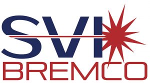
A full-harp replacement represents a major maintenance task that is costly, requires a precisely engineered component and field welding according to the ASME Boiler and Pressure Vessel Code. A critical point to remember: Often, upset conditions which caused an initial tube failure, have also damaged other tubes, making harp replacement the most practical option.
Catalyst replacement is a major maintenance issue, too, but if catalyst degradation is simply attributed to normal operation, then planning for catalyst change-out should be straightforward. By contrast, steam-stop-valve replacement represents a major undertaking that requires careful planning. Replacement of large pressure components is not easy.
FAC. Many HRSGs worldwide continue to be plagued by the phenomenon of single-phase flow-accelerated corrosion (FAC). In large part, this is due to the difficult-to-extinguish mindset of the need for reducing-agent/oxygen-scavenger feed to the condensate. FAC-induced failures in feedwater systems and economizers are said by some experts to have caused several fatalities in the power industry over the last three-plus decades.
For steam generators served by feedwater systems containing no copper alloys (which includes virtually all of today’s HRSGs), reducing agents should not be used; an oxidizing water-treatment program—such as all-volatile treatment oxidizing (AVT(O)—is correct.
HRSG chemistry guidelines are covered in many documents available to you at no cost, but a key point regarding this discussion is that for HRSGs still on reducing-agent feedwater treatment, or that were on it in the past, nondestructive evaluation (NDE) of FAC-susceptible locations is critical.
These include the tight-radius elbows in economizers and evaporators, and other locations downstream of flow disturbances in the feedwater and low-/intermediate evaporator networks. Another issue is the phenomenon of two-phase FAC, which commonly occurs in deaerators and HRSG low-pressure drums. Visual inspections often can confirm this corrosion.
 Wrap up. The importance of regular HRSG inspections and corrective maintenance cannot be overemphasized. Neglect of these tasks can lead to failures that cause unit outages and cost a company many tens of thousands of dollars for repairs and purchased power. More importantly, some potential failures jeopardize employee safety. That is the ultimate cost.
Sponsored content from Bang&Clean Technologies AG and GE Gas Power
By Marc Keusch, John Weimar, and Kenneth Hutchison
As grid dynamics evolve, plant efficiency and fuel costs have become increasingly important for combined-cycle asset owners. Operators are requesting low-cost support to achieve incremental gains in performance of their assets to ensure they can continue running profitably with as minimal impact to other maintenance work as possible.
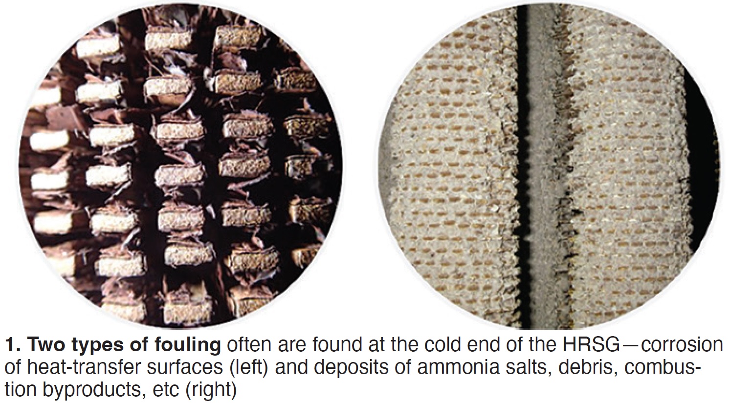
User challenges. On the gas side of finned tubes, two types of fouling often are observed in the cold end of the HRSG: corrosion and deposits (Fig 1).
Corrosion occurs when water and carbon steel interact, causing oxidation. Spallation of the material on the tubes (rust) leads to reduced surface area, impacting HRSG heat-transfer efficiency and potentially causing reliability issues (leakages).
Different types of deposits can accumulate on the finned tubes—typically these:
- Ammonia salts downstream of the SCR.
- Sulfur deposits if fuel has high sulfur content (natural gas or oil).
- Debris from insulation damage, upstream damage, or broken equipment.
- Combustion byproducts from liquid fuel firing (ash and contaminants).
Fouling penalizes combined-cycle performance in two ways:
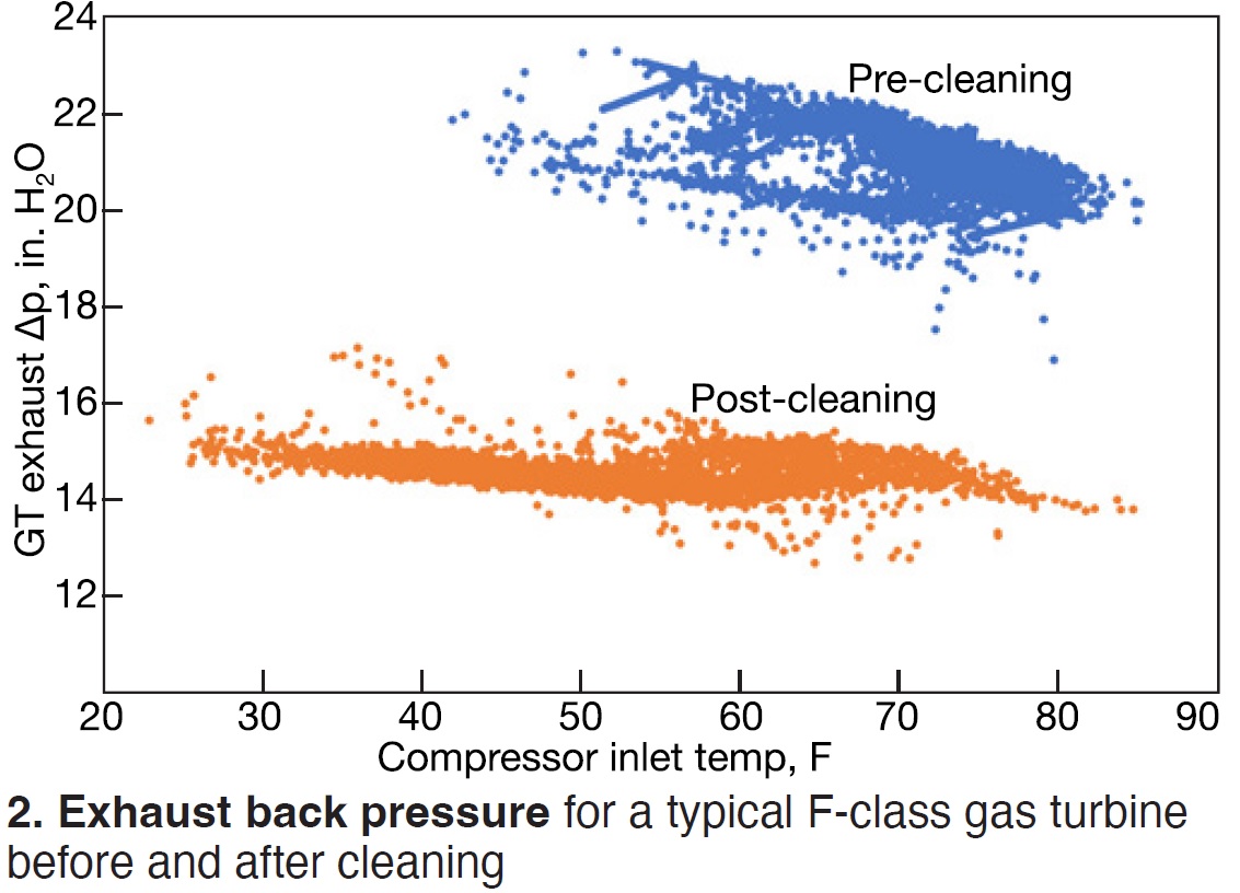
- It increases gas-turbine backpressure (Fig 2). Recall that the HRSG is designed aerodynamically in the gas path. Fouling disrupts this flow, increasing the backpressure and slowing the rotation of the gas turbine. Result: Reduced GT power output and increased fuel costs to maintain the same mass flow at lower efficiency.
- It reduces HRSG heat-transfer efficiency, thereby increasing the moisture content of the steam produced and reducing steam-turbine output.
The deep cleaning effect. To remove fouling from HRSGs, a special bag is positioned between HRSG modules via rigging and a flexible lance. The bag is filled with a gas mixture which then is detonated. Combustion of the gases results in a pressure wave that propagates through the tube bundles and dislodges the debris, which then falls to the lower vestibule in dry form. The placement and spacing of the bags prior to the pressure-wave initiation follows a grid-like pattern throughout the equipment. Each cleaning grid is based on the studied pressure drop off over distance, and the degree and composition of fouling.
The standout benefit of PressureWave+ (PW+) is the engineered, deep cleaning of the tube bundles. The PressureWave+ technology, developed by Bang&Clean Technologies in Switzerland, has been in use for over 20 years worldwide and has been applied successfully by GE on more than 375 HRSG cleanings in combined-cycle plants globally. Cleaning significantly reduces fouling made up from corrosion products, sticky salts, corrosive sulfur powders, and incompletely combusted fuel byproducts.
PW+ has proven effective in cleaning tube bundles of 10 or more rows deep while effectively removing fouling from tubes in bundles twice that depth. This includes tubing arrangements that are in alignment or offset and of different designs, as well as those impeded by structural members that could hamper access and cleaning efficiency.
User benefits. PressureWave+ technology provides plants these benefits:
- Cleaning risks to equipment and personnel mitigated through engineered technology.
- Safe continued work on the turbine and to the outside the HRSG during the cleaning.
- Deep cleaning in areas that cannot be reached by conventional technologies.
- Two to seven times more debris removed than with conventional methods.
- Cleaning done in 25-50% of onsite cycle compared with conventional methods.
- Faster cleaning following plant shutdown (even before HRSG is completely cooled).
- No water, no chemicals used on the tubing, thereby reducing corrosion potential.
- No scaffolding needed.
- Fast mobilization.
HRSG structural integrity. Many customers have asked if the PressureWave+ cleaning process is safe for the mechanical integrity of aging pressure parts. Multiple studies describe and systematically confirm safety and effectiveness.
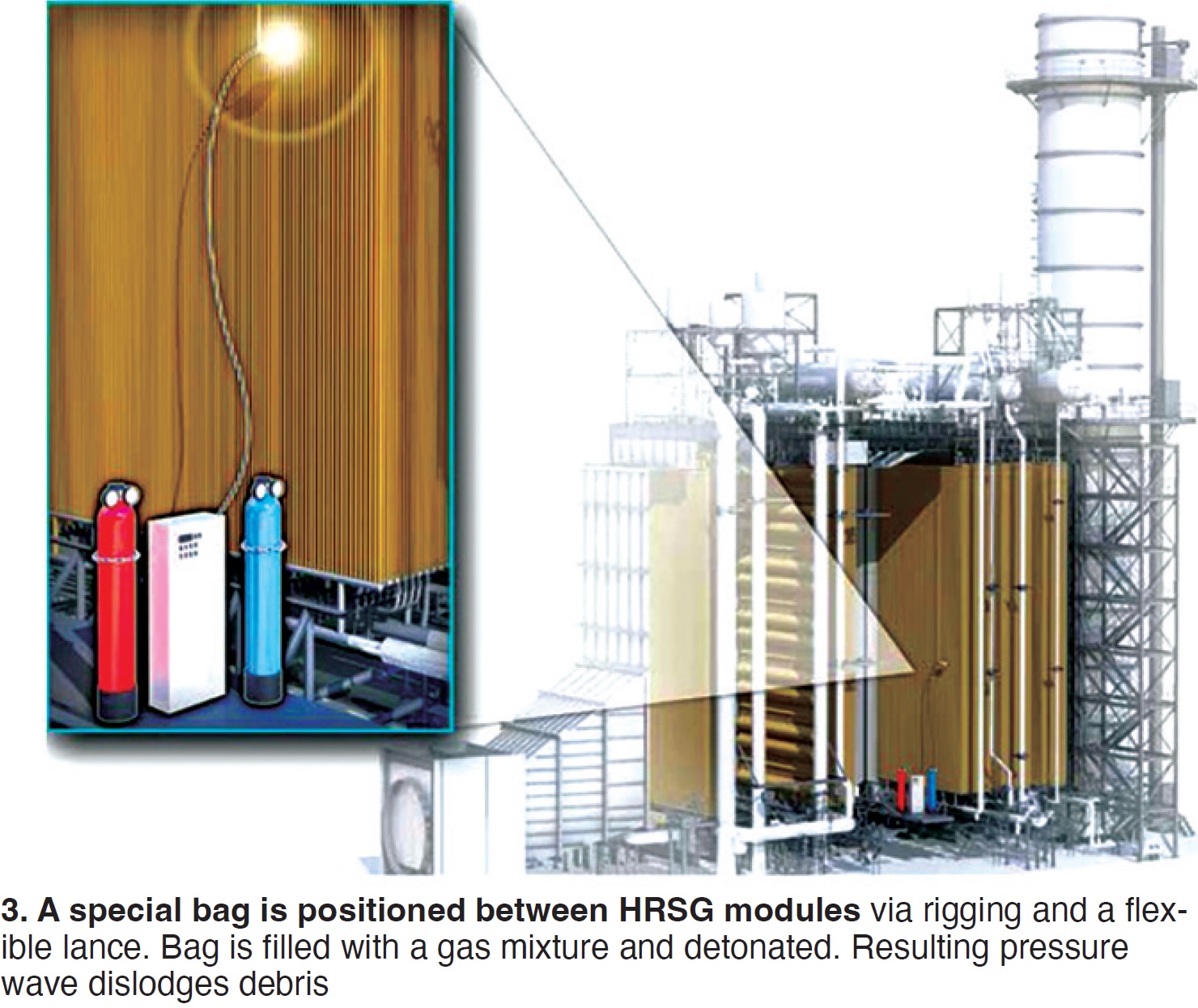
First, effective cleaning deep into the bundles is possible without manual handling or high explosives. User-funded research institutes, Bang&Clean, and GE collaborated on data collection and analysis to define the results observed during outages. Fig 3 shows how the pressure waves interact with the tubing to clean deep into the bundles. This demonstrates the observed cleaning of tubes shielded directly from the PW+ tooling.
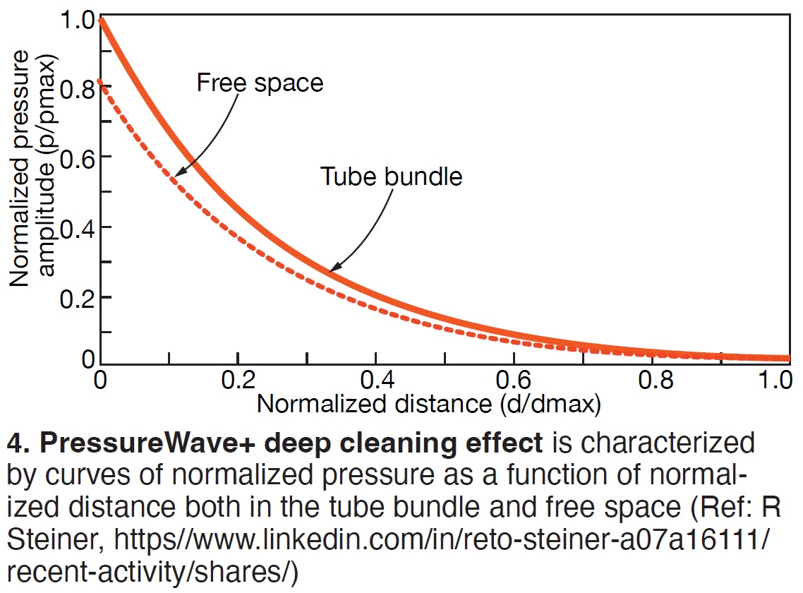
When comparing the pressure amplitude in the free space with that in the tube bundle, the amplitude within the bundle is higher. This amplification within the bundles is attributed to the interaction of the pressure wave shock front reflecting both off the tube walls and itself. This integration of waves (mach reflections) allows for removal of the debris that has built up on the back side of the tubing, thus increasing cleaning effectiveness (Fig 4).
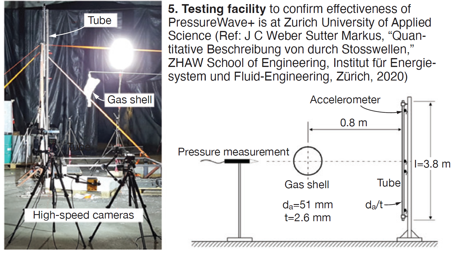
PressureWave+ wave propagation and its strength influence on structures was investigated and validated by simulation (Fig 5). Using existing and new data, numerical stress analyses were completed (Fig 6). The modeling led to this conclusion in the Zurich University of Applied Science review, “In the considered realistic load cases, a permanent deformation due to the detonation can be excluded.”
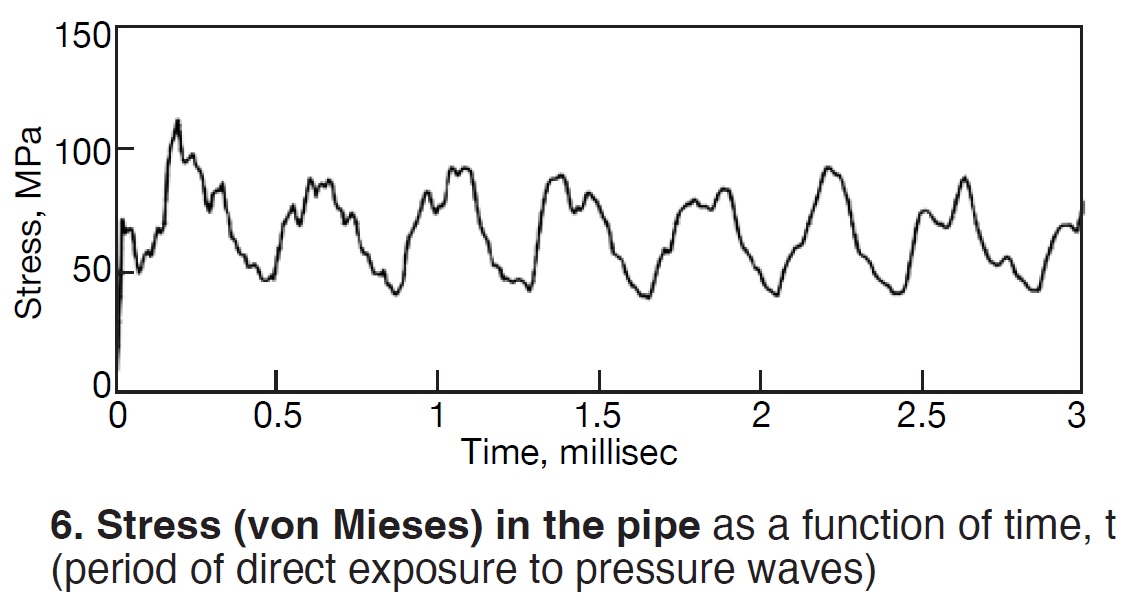
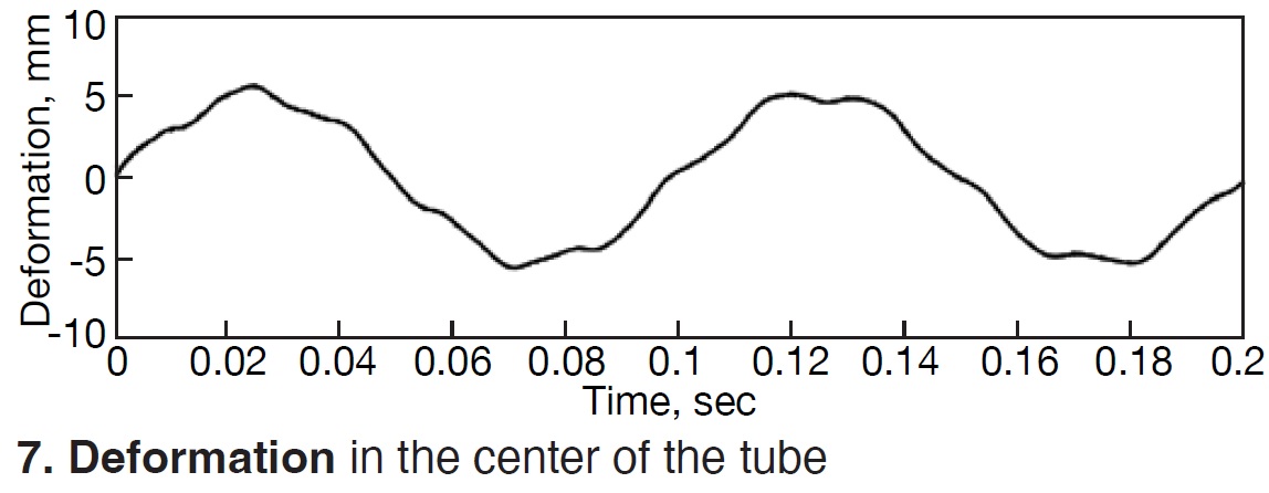
The testing and modeling also detail impact and tube to weld seams experience the greatest stress. This is where the greatest deflection can be observed. It is assumed the resulting harmonic. This harmonic did not result in permanent deformation (Fig 7).
Finally, the PressureWave+ technology was originally designed to clean waste-to-energy boilers during operation. As such, the risk of causing damage to an online unit which would require shutdown was unacceptable and had to be mitigated. Pressure-wave strength and speed are optimized for where effective cleaning is possible, and the risk is mitigated for boiler components. The evidence to support these claims includes the following:
- Scientifically reviewed by the Zurich University of Applied Sciences.
- EPRI review of speed and energy of the pressure wave.
- Over 20,000 successful cleanings of steam generators since 2001.
- More than 375 HRSG cleanings.
Case studies on generation M&D, predictive analytics, capacity/fuel demand forecasting, and performance testing

This webinar series, presented by Primex Process Specialists, is directed specifically towards power plant owners and operators to introduce machine-learning basics and how this rapidly evolving technology can improve power plant availability, capacity, and efficiency. Each webinar will include a 30-minute live presentation followed by Q&A with audience members.
 Introduction to Machine Learning and Power Plant Use Cases
Discover how machine learning works, how it differs from AI and an overview of how it can (and cannot) be used in the power plant environment to improve availability, capacity, and efficiency.
Date: Tuesday June 13th, 2pm ET
Power Plant Machine Learning Use Case # 1: Generation Monitoring and Diagnostics
Combined with human expertise, machine-learning can transform asset productivity and value. Attend this webinar to learn how this rapidly evolving technology accelerates recognition, quantification, and realization of high-level performance improvement opportunities.
Date: Tuesday June 20th, 2pm ET
Power Plant Machine Learning Use Case # 2: Capacity and Fuel Demand Forecasting
Accurately predicting the future has always been valuable. Learn how managers responsible for generation assets bidding into day-ahead merchant markets can realize greater accuracy in daily forecasts of capacity and (for some) fuel consumption with machine-learning.
Date: Tuesday June 27th, 2pm ET
Power Plant Machine Learning Use Case # 3: Performance Testing and Guarantee Validation
Making investment decisions and quantifying value around generating unit upgrades or repairs can be tricky business. Discover how machine-learning helps untangle performance data to gain accuracy and confidence in test results for comparison with supplier performance guarantees, asset valuation and vendor compensation.
Date: Tuesday July 11th, 2pm ET
The Power Users’ Mega Event—incorporating the annual conferences of the Combined Cycle (CCUG), Steam Turbine (STUG), Power Plant Controls (PPCUG), and Generator (GUG) Users Groups, plus the Low Carbon Peer Group—is only about three months away (August 28-31, Omni Atlanta Hotel at CNN).
Consider getting your travel request into management early so you don’t miss what many users believe is the industry’s most comprehensive conference/vendor fair and networking opportunity for supervisory personnel, engineers, and technicians involved in plant operations and maintenance.
Gas and steam turbines, generators, HRSGs, control systems, and emissions controls are all high-profile presentation/discussion topics on the agendas of the five groups. Recall that a ticket to any of the user-group meetings gives you access to all. Meals and vendor fair are joint activities.
Keep up on program developments in the coming weeks with a periodic visit to www.powerusers.org to review current agendas.
CCJ ONsite’s highlight reel from last summer’s meeting, which follows, offers the opportunity to evaluate the depth of content you can expect at this special event and assist in your decision-making.
The confluence, in one hotel in San Antonio, Tex, of knowledge, experience, and expertise on how to keep the nation’s aging gas-turbine-powered generating facilities operating in the face of shoestring budgets, supply-chain disruptions, and labor shortages, was perhaps unprecedented.
Over 350 users participated, with a slightly higher number of vendor representatives,
Critical condenser safety event
If you never thought a condenser could explode (as opposed to over-pressure), don’t feel bad. Neither did most of the attendees in the CCUG session listening to a representative from a major Texas utility explain how it happened at one of their combined-cycle plants. If you operate a plant with a “performance” fuel-gas heater (FGH) taking heat from the water/steam cycle (in this case from the intermediate-pressure circuit), you will most certainly want to review this presentation immediately and consider the recommendations arising from the utility’s fleet assessment of this situation.
Like most catastrophic (or potentially catastrophic) events, several unique factors had to align, as detailed in HRSG Forum, CCJ No. 72, p 42. Above all, the plant was in an abnormal outage during which the ST/G was forced out of service, and the GT/Gs were maintained in “ready” mode for the grid, meaning that fuel lines were at pressure up to the emergency stop valves. Other factors included, but were not limited to, a leaking FGH isolation valve; plugs in the tubing of the FGH shell-and-tube exchanger having fallen out; a delta P across the FGH pushing natural gas into the water/steam circuits, then through the drain lines terminating at the condenser; and others.
You have to review the referenced article to fully appreciate the details behind the factors which ultimately led to a buildup of natural gas in the condenser over an 11-day period to a percentage between the lower explosive limit (5%) and the upper explosive limit (17%).
When a welder struck an arc to replace a 1-in drain line on the condenser’s outside wall, an explosion occurred followed by a shock wave felt across the facility. The welder was not required to test for presence of combustibles because the hot work was outside the condenser.
Thankfully, no injuries occurred, no condenser tube leaks resulted, but six overpressure rupture disks on top of the condenser blew out and landed across the facility (one narrowly missing a worker), there was major damage to some structural steel inside the condenser, and the low-pressure turbine cover lifted six inches when bolting threads failed.
The bountiful list of after-event recommendations range from identifying all vessels where gas can accumulate to reassessing FGH design, especially the need for the bypass valves.
Catastrophic arc-flash event
Also at the CCUG, a representative from a 750-MW, non-utility combined-cycle plant in the Northeast reported on an arc-flash event with the 230-kV line into the plant, which resulted in a 10-in. hole in the ground when it hit below, and the loss of ac power to the plant. With no black-start capability, the relatively inexperienced crew onsite (and an operator in the control room who had “just qualified”) at the time had to get the emergency diesel/generator (EDG) online and synchronized, a process which should have taken three minutes but ended up taking 15.
The arc-flash event occurred when someone at the facility next door, a large warehouse operation, used a man-lift to replace a bulb on an outdoor light pole/fixture under the transmission line. It was discovered later that the neighbor firm had no plan/procedures in place for work near an energized line. Miraculously, the worker on the lift was not harmed. Nor was the person from the fire department who responded to the emergency and used the truck ladder to rescue the person on the lift. He performed this without knowing whether the line was energized or not. There was no collateral damage to the combined cycle.
Again, a confluence of factors had to line up for this event to occur. One was the fact that the normal power feed breaker did not open on loss of ac power, which meant that the EDG could not synch to the 480-V bus. The plant revised the procedure for EDG ops to include what to do if the normal power breaker does not open, and simplified what was previously a confusing EDG control scheme layout.
The light poles under the line have been removed, a physical barrier has been installed 20 ft off the centerline of the overhead line, and warning signs were hung along the fence line adjacent to the T line. All pre-job briefs now include a discussion of hazards associated with work near the 230-kV line.
Turning gear: Achilles heel?
Meanwhile, over at the STUG meeting, a utility expert noted that the steam turbine/generator’s turning gear (TG) could be a “pinch point” for ST/G reliability in plants that are starting and stopping more frequently to follow renewables. The utility had experienced a catastrophic failure of a TG motor caused by imbalance and a spare motor was not readily available.
It’s easy to forget that, in many cases, the TG probably was designed to operate perhaps 10 times a year, but under future operating scenarios, this person noted, that could increase to 500 or more (yes, multiple starts per day). Having the requisite spare parts in inventory or readily accessible is advisable, or perhaps even a motor in stock that could fit several different units. Also good to distinguish the number of hours the TG operates versus the unit itself and plan/adjust maintenance and spares accordingly.
The presentation slides at the STUG conference archives are replete with descriptions of different types of TG units and drive motors, photos of failure mechanisms, and recommendations for safety, spares strategy, and inspection procedures and frequencies. Also, you can dive a little deeper here in CCJ.
Control-system supply chain
Attendees in the PPCUG room wrestled with serious supply-chain challenges. Among them: Extending the use of processors slated for obsolescence because replacements are not available, “allocations” (read, rationing) of CPUs (central processing units) for specific families of controllers, lead times which have been extended by 50% to 100% since 2019 for many components and systems, and plants having to postpone and reschedule control system upgrades and other work, with suitable incentives and discounts offered, to ease the pressure on OEMs.
Thankfully, these issues have caused one control-system supplier to change its procurement system which the OEM presenter acknowledged was “not that sophisticated.” For one thing, they relied on too many single-source suppliers, one of which, in another admission, was their own company. Today, the OEM has visibility into its sub- and sub-sub supplier network, or what he termed “digital surveillance” of the supply chain, and could more appropriately forecast delivery times and/or problems.
Generally, control-system specialists expect these challenges to last at least another 18 to 24 months.
Briefs
The Power Users highlights reel also included the following:
- Owners are now seriously studying the impact on performance of extracting significant quantities of low-pressure steam for a carbon-capture process on the premises.
- A utility operator said they were entering a “no man’s land” with respect to the hours some of their units were running. “How do we instrument these assets for safety and reliability and feel better” about operating them, he asked?
- Cold-weather action items are tracked and managed by one utility’s power operations center, a centralized M&D facility, serving most of the assets in the fleet, as regulators like Ercot and NERC issue new winterization rules and standards.
- Rupture and repair of a low-pressure crossover bellows on an ST/G with over 110,000 service hours at time of failure was examined by one utility STUG presenter, followed by another from a separate utility plant which experienced the same failure.
- Steam-turbine valve maintenance is being neglected at too many plants, said one consultant. Contrary to popular belief, grit blasting does not remove oxides, which are responsible for 80% of valve sticking problems.
- The travails of designing and periodically testing (twice annually) a black-start plant with an 850-Vdc, 13.7-MW, 3.4-MWh battery unit starting a single GT/G in California was discussed by a major non-utility owner/operator.
- A prominent Texas utility reviewed seven separate case studies from the last five years of L-0 (last stage) steam-turbine blading, each example a different combination of OEM, blade length, type of plant, failure mechanisms, root causes, etc. Generally, L-0 blades are a high risk and potentially impactful component in the ST/G, he said, and OEMs have issued several service bulletins around them. Often, there are no operating indications of an issue before an event occurs.
- An OEM updated the GUG audience on a new robotic wedging technology designed to re-tighten wedges faster and without wedge removal but does require a “rotor out” outage and about a shift’s worth of time to install.
- Another ST/G OEM, in a STUG session dedicated to recent service bulletins and top issues, said his firm is now recommending that all ST/G units undergo annual last-stage blade inspections and that they are discovering “numerous and surprising” indications in critical locations of HP and IP shells in units 15 to 20 years old.


