ASK THE LEGACY TURBINE DOCTOR
By Luke Williams, PE, Consultant
www.geLegacyGasTurbineSupport.com
Editor’s note: Luke Williams and his business partner, Don Melsheimer, have decades of experience supporting owner/operators of GE gas turbines (MS5001, 6B, 7EA, F, and FA frames, plus LM2500 and 6000 aeros) requiring troubleshooting assistance with their control systems (Fuel Regulator through all versions of the Speedtronic™ from Mark I through the VIe).
Williams recently penned this article to make plant management aware that sometimes gas-turbine rotors and other hot parts are not as far into their lifecycles as you might think, or be led to believe. The possible benefits to owner/operators of not having to do NOW, a combustion or hot-gas-path inspection based on traditional thinking, might include deferring expenses to a more convenient time, extending maintenance intervals, building flexibility into your outage schedule to take advantage of market opportunities, etc.
Williams relies on equations and logic readily available in GE documentation to walk you through the arithmetic to determine how much flexibility your plant’s operating profile might allow. You could learn that an operational tweak here and there might make a measurable difference on the bottom line. Williams’ goal is “not to leave any money on the table.” Another thought: If operators are more cognizant of how they might add value to their plant’s mission there could be financial rewards for them.
If you plan on attending the upcoming Legacy Turbine Users Group annual conference, July 15 – 18, at the Woodlands (Tex) Waterway Marriott Hotel, and want to learn more, stop by Booth 20 during the vendor fair to chat with Williams and Melsheimer.
“Gas Turbine Rotor Inspections,” published as GE Technical Information Letter (TIL) 1576 in June 2007, discusses the requirement of GER-3620, “Heavy-Duty Gas Turbine Operating and Maintenance Considerations,” that rotor inspections be performed at specific intervals recommended by GE. These intervals, unless otherwise specified, are 5000 factored starts or 200,000 factored hours.
The revision of GER-3620 when TIL 1576 was released was “K” (October 2004). The latest revision, “P,” was published in January 2021. O&M discussions in GER-3620 are generally applicable to all GE heavy-duty gas-turbines—Frames 3, 5, 6, 7, and 9. Managers and technicians with O&M responsibilities for these engines should consider having copies of both documents at the ready and be knowledgeable as to their content.
The section of GER-3620K on firing temperature (p 9) describes the relationship of firing temperature to maintenance factor thusly:
- Each hour at peak-load firing temperature—that is, baseload firing temperature +100 deg F—is the same as six hours of operation at baseload. “This operation will result in a maintenance factor of six.”
- “It is important to recognize that a reduction in load does not always mean a reduction in firing temperature.” The text then explains that the IGV (inlet guide vane) temperature control and DLN turndown affect firing temperature by reducing air flow to maintain high exhaust temperature for combined-cycle and DLN stability. The key phrase was italicized by the editors.
The relationship between firing temperature and turbine exhaust temperature is nearly 1.66:1. For base to peak operation, an exhaust-temperature increase of 60 deg F results in a firing-temperature increase of 100 deg F. Conversely, an exhaust-temperature decrease of 60 deg F results in a firing-temperature decrease of 100 deg F.
Reference to firing temperature related to peak load was introduced in GER-3620 Revision F (November 1998). The paragraph in Rev F continued to be part of GER-3620 until Rev N in October 2017.
GE indicated that an increase in maintenance interval could be expected from part-load operation on p 9 of GER-3620 Rev L, dated November 2009. Industry experience has shown that operation at less than base or peak load has extended the on-condition maintenance of gas turbines. Units that are baseload but operate at less than the base rating, such as part-load dispatch, also have exhibited extended life.
Note that “on-condition” is an aero term for a preventive primary maintenance process that requires periodic inspection of a system or component to determine if it can continue in service. The idea is to avoid a failure during normal operation.
GER-3620 provides calculation criteria for determining factored starts and hours. Calculations are based on turbine operating procedures such as hot, warm, and cold starts, trips, load condition, and turning-gear operation. The hours-based rotor-life equation presented in Rev K is
MF = [BLH + (2 × PLH) + (2 × TGH)] ÷ BLH + PLH (Eq 1), where:
MF is maintenance factor,
BLH is baseload hours,
PLH is peak-load hours, and
TGH is turning-gear hours.Note to Frame 6B users: The typical MS6001B DLN1 is not peak capable and does not have a turning gear.
If the unit was operated at peak load 100% of the time, the MF would be 2.0. The rotor-life calculation allows a reduction in the MF as it applies to the rotor structure itself (for hot-gas-path parts, the MF is 6). Thus, as Eq 1 shows, if the unit did not operate in peak mode and did not have a turning gear, the MF would be 1, and result in an hours-based rotor life 200,000 hours.
It follows that if the unit operated in peak mode 100% of the time with an MF of 2, the rotor-life maintenance interval would be 100,000 fired hours. That a given, operation at part load with the firing temperature 100 deg F less than the design value should increase the interval.
The rotor-life maintenance interval would be 200,000 plus 100,000 fired hours or 300,000 fired hours. The part-load maintenance factor based on 100 deg F less than design firing temperature would be:
MF = 200,000 ÷ rotor maintenance interval of 300,000 = 0.667 (Eq 2).
Real-world example. An MS6001B-powered plant in the Midwest has an operating condition that limits gas-turbine output to an average of 84% of its baseload rating. The limit is based on the ability of the steam customer to accept the baseload steam generated. In 2013, the unit had reached over 50,000 hours without a major inspection. The 2013 inspection found very few problems with the compressor and hot section.
Data were retrieved from the data acquisition system over the span of one year, January 2021 to December 2021. The compressor discharge exhaust temperature control curve, TTRXP, was calculated using the compressor discharge pressure (CDP). The exhaust temperature, TTXM, was subtracted from the CPD exhaust temperature control curve, TTRXP, thereby allowing a comparison of the turbine maintenance factor based on the 200,000-hr limit to the maintenance factor adjusted for the hours the unit was operated at temperatures less than baseload.
Results from the data compiled for year 2021 are as follows:
- Median turbine exhaust temperature, 1015.63 deg F.
- Median compressor discharge exhaust temperature control, 1046.79 deg F.
- Median delta exhaust temperature, Tx = 30 deg F.
- Median delta firing temperature, Tf = 50 deg F.
The part-load MF for ΔTf is the following:
0.667 + [(1 – 0.667) × (Tf deg F ÷ 100)] (Eq 3)
Thus, the part-load MF for 100 deg F is 0.667 + [(1 – 0.667) × (100 ÷ 100)] = 0.667 + [0.333 × 1] = 1.
Using the same methodology, the part-load MF for 50 deg F would be 0.835. And, the part-load maintenance interval, 200,000 ÷ 0.835 or 239,952 fired hours. Or, 10,048 hours less than the 250,000-hr design life of the rotor and 39,808 hours greater than the baseload maintenance interval.
The results are based on one year’s data and was done to evaluate the effect on maintenance interval of continuous operation at less than baseload conditions. The unit has been operating for over 25 years. The next step would be to obtain data back to initial operation and repeat the calculation to verify that the overall operation has been at firing temperatures below the limit of the compressor discharge pressure and megawatt temperature control curves. “Local knowledge” is that 2021 was representative of operations in prior years.
In June 2023, timers were installed in the plant’s Speedtronic™ Mark V control system to record the fired hours from 1.0 to 15 deg F below base reference, 15 to 30 deg F below base reference and more than 30 deg F below base reference. Results of data taken in March of 2024 are presented in Table 1.
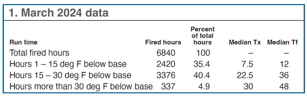
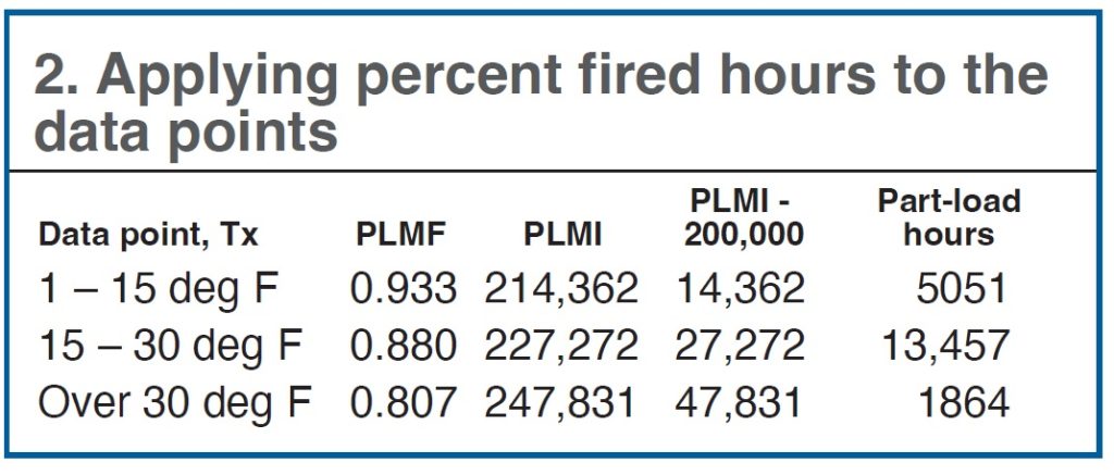
Next step: Calculate the part-load maintenance intervals (PLMI) using the actual median firing temperatures (right-hand column in Table 1). For the 1 – 15 deg F case (first line in Table 1) with a Tf of 12, Eq 3 reveals:
0.667 + [(1 – 0.667) × (100 – (12 ÷ 100))] = 0.667 + (0.333 × 0.88) = 0.667 + 0.266 = 0.933.
Thus, the PLMI = 200,000 ÷ 0.933 = 214,362 fired hours.
For a Tf of 36 (second line in Table 1), the part-load maintenance factor (PLMF) is 0.880 and the PLMI, 227,272 hours.
For a Tf of 48 (third line in Table 1) the PLMF is 0.807 the PLMI, 247,831 hours.
Applying the percentage of fired hours to the three data points:
The original data collected in 2022 estimated a part-load rotor maintenance interval of 239,952 fired hours. The actual data collected in 2024, considered more accurate, produced an interval of 220,372 fired hours, or 18,580 hours less than estimated two years earlier.
As noted above, GER-3620 Revision L, says that an increase in maintenance interval could be expected from part-load operation. Plant experience confirms that operation at less than baseload or peak load extends the on-condition maintenance of gas turbines. Baseload units that operate at less than the base rating also have shown extended life. The OEM could be approached to allow an increase in part-load maintenance intervals.
Plus, the part-load data can be applied to other maintenance intervals—such as combustion, HGP, and major inspections. The basic calculation of maintenance interval as given in GER-3620P, February 2021, is the following:
Maintenance interval = Baseline combustion inspection ÷ Maintenance factor.
Further, Maintenance factor = Factored hours ÷ Actual hours, and factored hours equals K × Af × Ap × ti, where K is the injection factor, Af the fuel factor, Ap the load factor, and ti the operating hours at load.
Important for users tending legacy GE engines:
- K normally is 1.0 for most non-DLN1 units, which generally are not injected.
- Af is 1.0 for gas fuel.
- Ap and ti are made up of part load, baseload, and peak.
Note that peak hours are recorded by a peak-load timer in Speedtronic control systems; DLN1 units typically are not peak-rated.
K, Injection Factor, normally is 1.0 for most Non-DLN I units. DLN I units are generally not injected.
Af, Fuel Factor, is 1.0 for gas fuel.
Ap Load Factor and ti, Operating Hours, is made up of part load, base, and peak.
Peak- and part-load hours are recorded by dedicated timers installed in Speedtronic control systems. Recall that DLN1-equipped units normally are not peak rated. The calculation procedure above for part-load operation could be applied to the calculation of part-load Ap.
Here’s a sample calculation for a 12,000-hr combustion inspection, following the same procedure as for the rotor-life calculation earlier:
PLMF = [(Combustion inspection hours ÷ Maintenance factor) – CI hours] × % Tx hours. For the part-load 1 -15 Tx deg F portion of the calculation, [(12,000 ÷ 0.933) – 12,000] × 0.354 = 305 hours.
Using the same methodology for part-load calculations of 15 -30 Tx deg F and over 30, the part-load hours for this combustion inspection would total 14,441. The ability to run more hours between combustion inspections than recommended by the OEM—in this case, 2441—may offer significant financial and operational benefits.