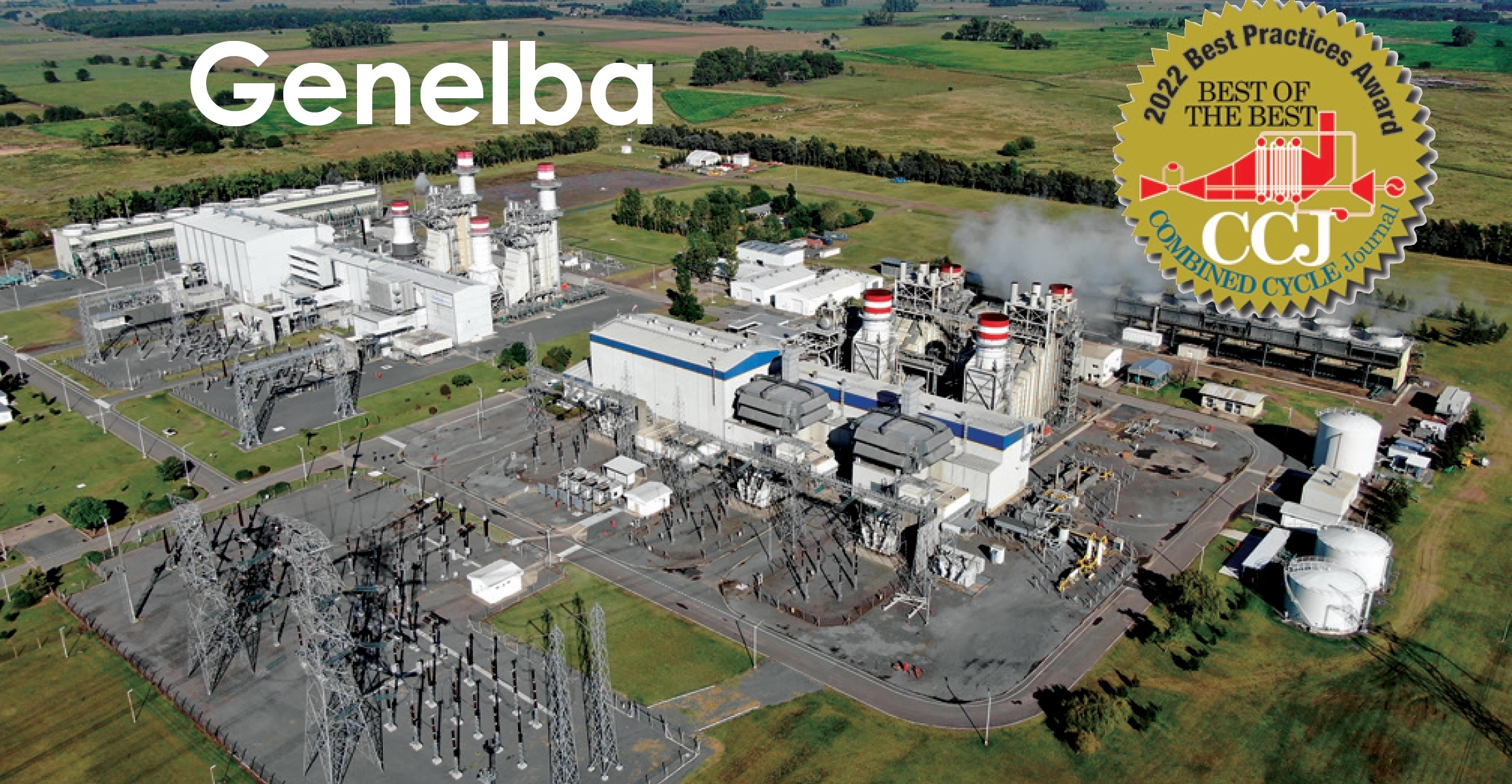
The first combined cycle began operating in 1999. It was repowered in October 2020 and today the gas turbines are rated 223 MW each, the steam turbine 238 MW. The second combined cycle is comprised of a 182-MW gas turbine called Genelba Plus, installed in 2009 and repowered in June 2019, and a 188-MW gas turbine installed in 2019. The 199-MW steam turbine was commissioned in July 2020.
The plant’s challenge was to develop a means for monitoring critical equipment to maintain Genelba’s availability and reliability at the facility’s traditional high levels.
The solution required creating and implementing a methodology for gathering information from multiple online and offline sources, developing key performance indicators (KPIs), and analyzing them under different boundary conditions as illustrated in Fig 1.
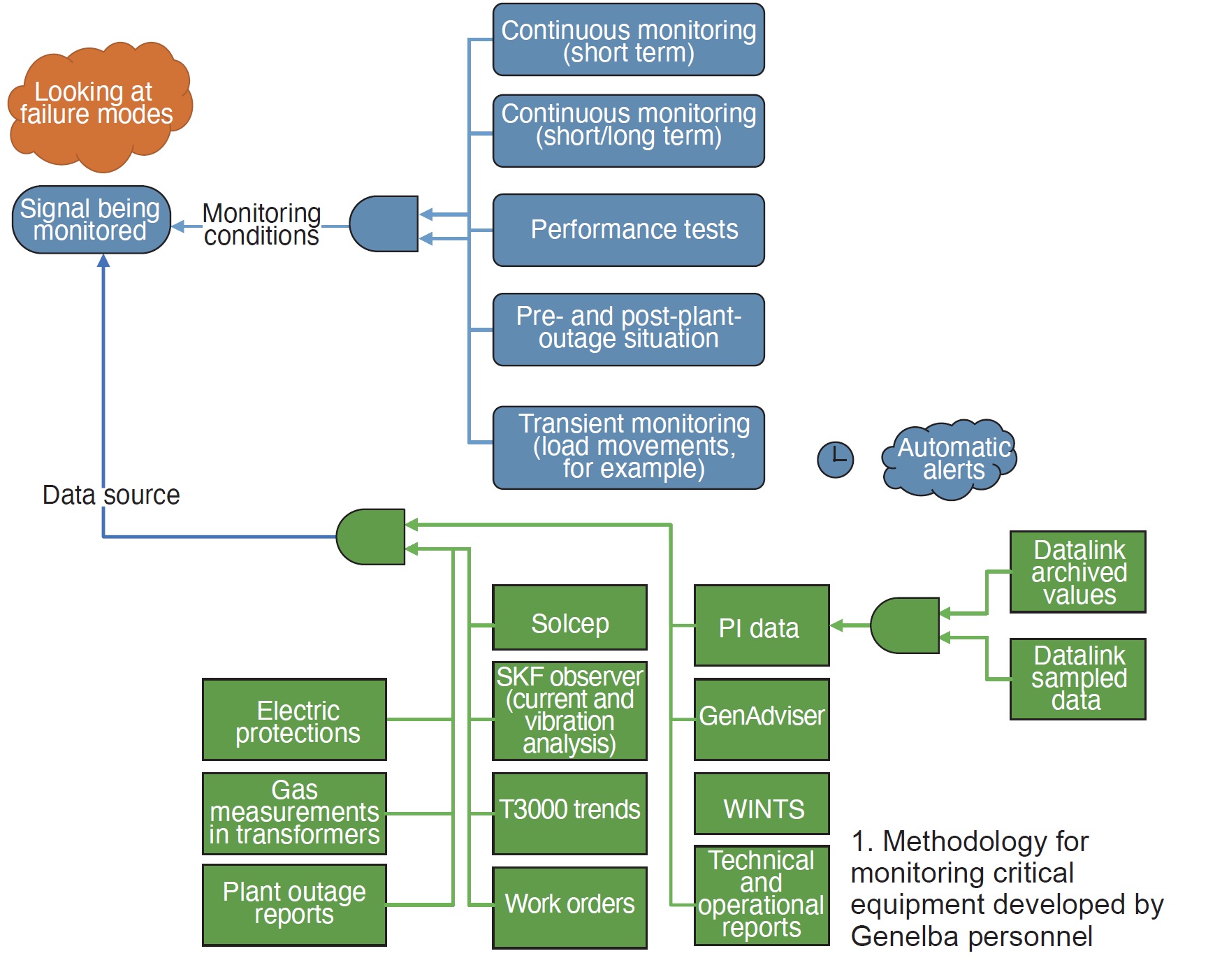
After identifying the available information resources, a process was developed and executed to answer the following questions, which were then programmed in an automatic execution algorithm in PI:
- Is the instrumentation proper and in good working order? Are additional sensors needed to monitor other equipment failure modes?
- Baseline definition (normal behavior).
- Does the signal change over time?
- Are there alarm signals coming from that system?
- What were the equivalent operating hours at the time of analysis?
- Is there a correlation with other variables?
- What consequences does the abnormality have?
- How are the measurements on the other machines?
- Is the system showing signs of failure—for example, is there an increase in the number of work orders?
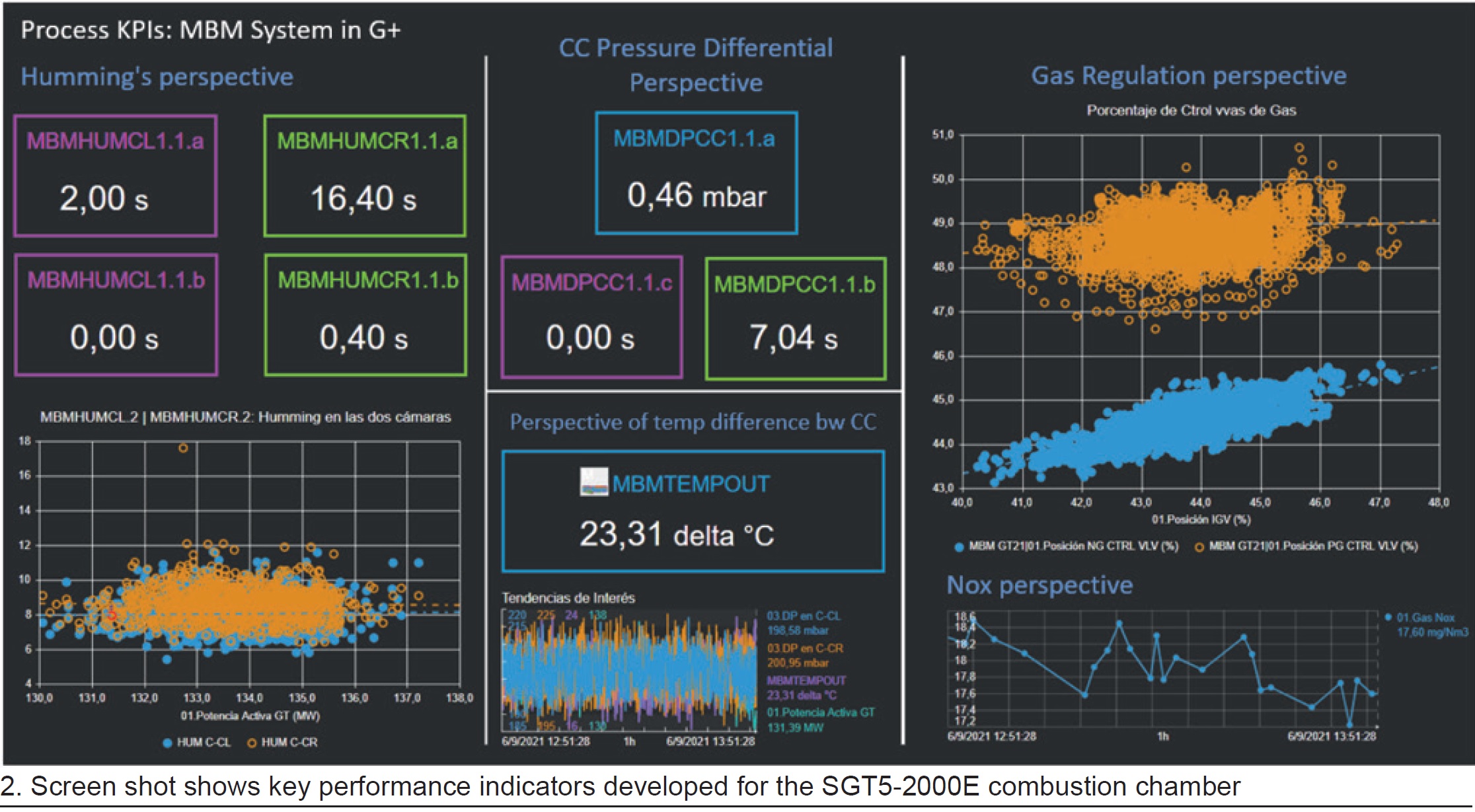
Genelba’s Best Practices entry form offered the following example of how the plant’s program works using the KPI MBMHUM1.1. Four binary signals from the control system are activated when the humming exceeds 20 and 30 mbar. (Recall that the plant’s SGT5-2000E gas turbines each have two combustion chambers.) The indicator counts the total time that both cameras were exposed to humming greater than 20 mbar and greater than 30 mbar in the last 15 days.
Presenting the information in this manner allows staff to analyze, for example, whether the machine was exposed to higher levels of humming after an inspection (where pilot valve control could be intervened). It also affords a comparison between both combustion chambers.
Fig 2 shows the KPI dashboard developed in OSIsoft’s PI Vision for the continuous monitoring of the combustion chambers. Using the methodology illustrated, and keeping in mind equipment failure modes, the plant’s technical experts are able to determine if it’s necessary to add more instrumentation to detect important failures early.
Continuing with the combustion-chamber example, staff found that addition of accelerometers could possibly identify conditions conducive to impending burner malfunction—such as the possible loosening of burner hold-down bolts. Fig 3 shows one of the sensors attached to a base that had to be welded to each burner to dissipate heat so the sensor would work within specifications.
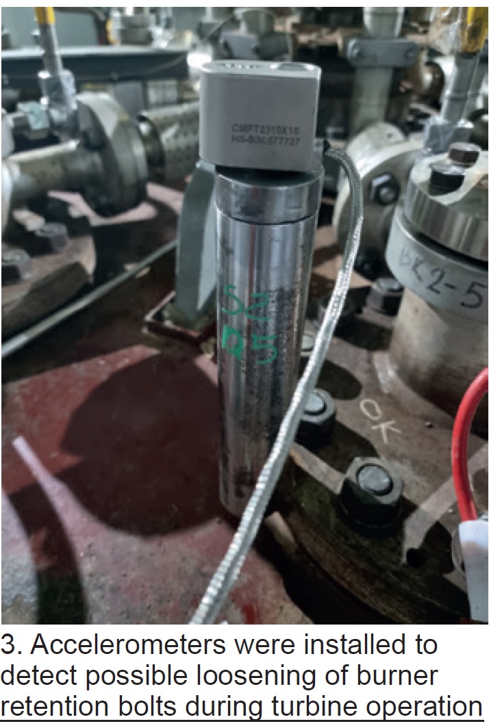
The accelerometer is wired to a high-frequency processor box that transmits the information via the plant’s industrial WiFi network to the processing server.
In sum, 18 accelerometers were installed on each engine. Information is sent to the PI system, from which a comparative dashboard was developed by sensor, camera, and gas turbine, with the goal of characterizing the cameras and determining abnormal behavior—because personnel did not have reference limits for these new measurements.
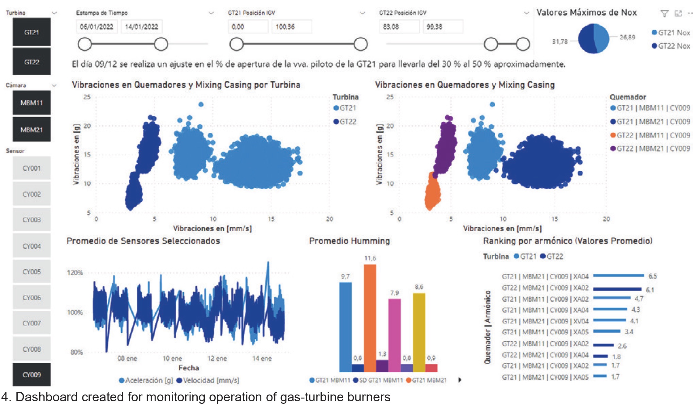
Fig 4 shows the board developed in Microsoft’s Power BI, an interactive data visualization software product, for tracking acceleration measurements. The graph at the upper left shows information from all the selected sensors discriminated by turbine; that at the upper right from selected sensors discriminated by turbine and sensor. The lower graphs show trend values, humming values, and vibrations per harmonic, respectively.
Here’s an example of how the development effort described above works: One of the indicators monitored—it infers thermal balance between combustion chambers—detected a deviation in GT22 of more than 15 deg C with respect to the allowed maximum. Staff analysis determined that fuel flows to one of the combustion chambers required correction.
Technical experts believed the anomaly might have been caused by a deformation in the right combustion chamber of GT22 that allows air to bypass the compressor, cooling it. Such a thermal imbalance over time can stress the first row of rotating blades, with the risk of fracture of some, and consequent damage in later stages.
The temporary fix implemented was to replace a gas orifice plate to redirect more flow to the combustion chamber experiencing deformation, thereby thermally compensating the effect. A permanent repair was planned for the next GT minor inspection.
The benefits of having the intel and implementing a temporary fix included the following:
- Staff could detect wear on the camera and plan resources and work in advance of the next planned inspection. Without such preparation, personnel believed an outage of at least five days would have been required to correct the problem, at an estimated cost of about $250k/day.
- Modifying the orifice plate in the gas pipe avoided progressive damage to GT22 airfoils and mitigated the risk of catastrophic failure.
- The possibility of improving instrumentation to measure humming values associated with GT protection more precisely was identified based on another of the developed indicators.
Experience the technical leadership of Bearings Plus.
Expert Repairs, Replacements and Upgrades
For Fluid Film Bearings and Seals
Return equipment to peak performance with expert rebabbitting and refurbishment of your bearings. Improve stability, control vibrations and accommodate rerates with custom upgrades.
Background: Legacy Turbine Users Group
The Legacy Turbine Users Group (LTUG), formed by Power Users earlier this year to facilitate the transfer of knowledge among members of the Frame 5, 6B, and 7EA Users Groups, greatly benefits owner/operators of these engines. With the number of experienced O&M personnel in decline because of staff reductions and retirements, it makes good sense to aggregate the talent on both the user and supplier sides for all to share—especially given that these GE engines have “common” elements.
LTUG’s first annual meeting was conducted as part of Power User’s Mega Event, Aug 29 – Sept 1, 2022, at the San Antonio Marriott Rivercenter, which attracted more than 350 owner/operators. Several reports on that conference are forthcoming. Here the editors review the backgrounds of the Frame 5 and Frame 6B organizations and salute BASF Geismar for its work in increasing the reliability of boiler drum-level controls. The 7EA Users Group, serving owner/operators of 7B-EA gas turbines, will be featured in the next issue of CCJ ONsite and include recent best practices from that fleet.
The GE Frame 5 is likely the most popular gas turbine ever produced for power and industrial applications. The first unit in this model series shipped 65 years ago from the OEM’s Schenectady (NY) shops and Frame 5s are still being built today—albeit by manufacturing associates abroad and at ratings about two and a half times those of the 12-MW models installed in the late 1950s and early 1960s.
Although more than 3000 of these machines have been sold over the years, the editors cannot find records of any formal user group meeting conducted since the millennium with the Frame 5 as its focus. Power Users believes this engine has value as a critical peaking asset and supported the launch of the Frame 5 Users Group as part of its 2022 Mega Event.
|
Frame 5 Users Group Steering committee, 2022 Josh Edlinger, Eastern Generation |
Frame 5s are, in a manner of speaking, “beasts,” and many don’t run very often. But that doesn’t mean they are immune to the problems found in more advanced machines that operate regularly and at higher temperatures.
Mike Hoogsteden, director of field services for Advanced Turbine Support, an industry leader in the conduct of borescope inspections to determine the condition of gas turbines and other assets, told the editors that a large majority of Frame 5 operators don’t perform semi-annual inspections, as do the large gas turbines running regularly. Depending on the run profile, a full compressor/combustion/turbine borescope inspection every one to two years probably makes best sense for many of these units.
Also recommended, and depending on unit designation, is an eddy-current inspection of all IGVs (fixed and variable) and the stage S0 or S1 stator vanes (first row of vanes). The EC scan would identify any cracks in the vanes.
Another location for a careful inspection is at the ninth-stage hook-fit, where component separation can be an issue. Recall that the thin ligament at the 10th-stage extraction slot forms the hook that holds one side of the ninth-stage stator vanes in place. It is susceptible to cracking that could allow one or more vanes to work free and go downstream causing major compressor damage (Fig 1).
If you are unfamiliar with how best to prepare for a Frame 5 borescope/EC inspection, contact your service provider. A couple of things Hoogsteden recommends: (1) For the combustion section inspections, provide access to every other one of the 10 cans via removal of the fuel nozzles; (2) gain access to the second row of turbine blades by availing access into the stack.
Hoogsteden then provided a flavor of what might be found with a borescope by sharing findings from three recent Frame 5 inspections. Engine A was a Model M, B a Model P, and C a Model N.
Engine A. The inlet section was found in relatively good condition, but there was rust and debris on the inlet floor. Inspector’s recommendation was to prep the floor for a two-part epoxy coating capable of withstanding regular water immersion.
The compressor section, accessed through the inlet bellmouth initially and later through the removed upper case, revealed partial liberation of the IGV tip shroud, causing significant downstream damage (Figs 2 and 3). An engineering review was recommended before repairing and restarting the unit.
The combustion section was in good condition; water wash residue was visible on the hardware. Combustion liners were accessed through the fuel nozzles in cans 3 and 7.
The turbine section, accessed via the combustion liners, also was in good condition. The exhaust section was not inspected.
Engine B. Rust and debris was found on the inlet floor of this unit as it was in Engine A. Inspectors accessed the compressor section through the inlet bellmouth, finding two stage S0 stator vanes had liberated at the 6 o’clock position (Fig 4) along with one R9 rotor blade (Fig 5). Result: Extensive damage throughout the compressor.
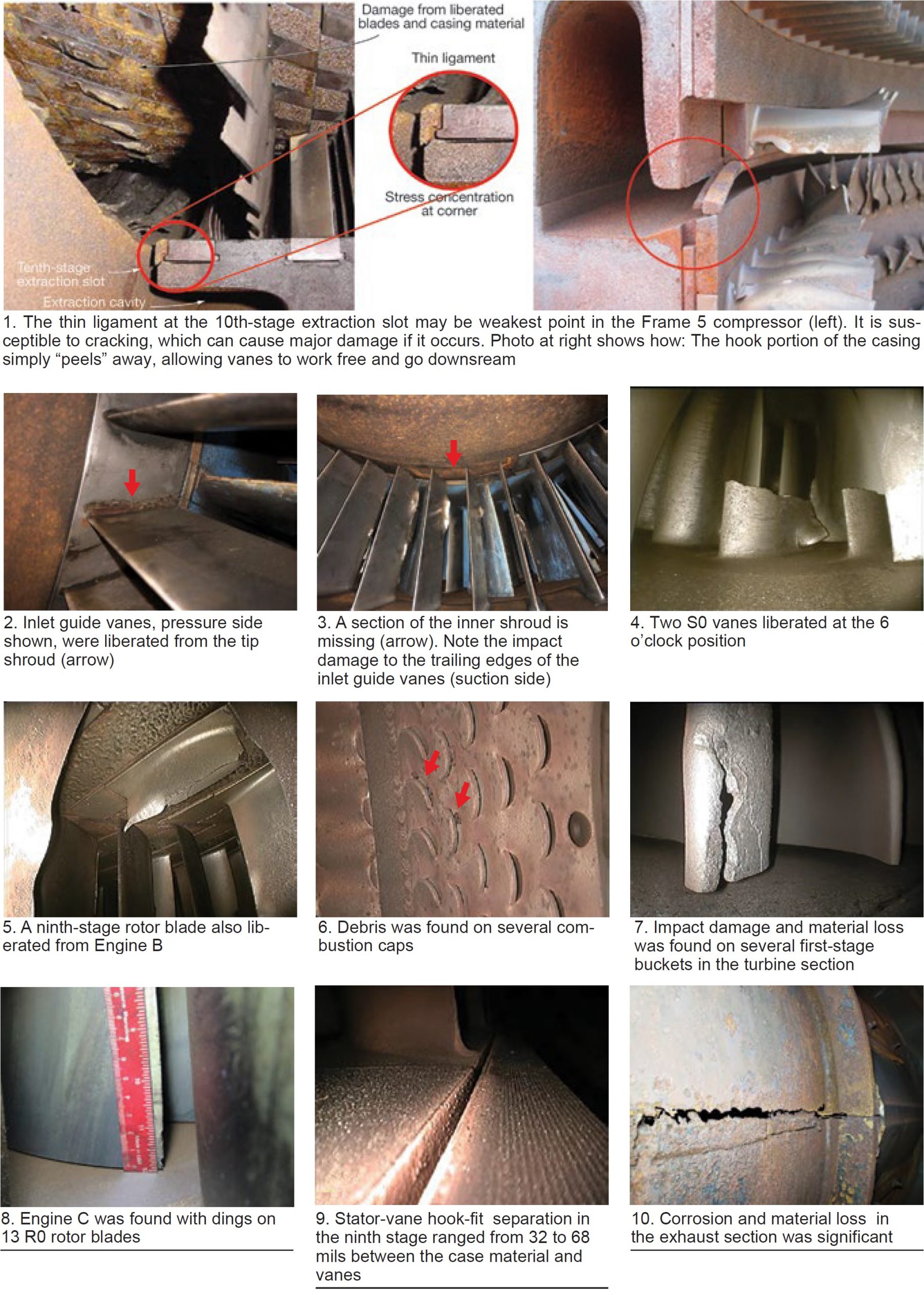
Combustion liners were accessed through the fuel nozzles, the turbine section via the liners and exhaust section. The combustion section was found in good condition except for some debris found in the combustion-cap air slots (Fig 6). Impact damage and material loss was suffered by a majority of the first-stage turbine buckets (Fig 7). Condition of the exhaust section was “good.”
Engine C. Access (1) to the compressor section was through the inlet bellmouth and the ninth-stage air extraction, (2) to the combustion liners via fuel nozzles and crossfire tubes, and (3) to the turbine section by way of the combustion liners and exhaust section.
Impact damage was found at the leading edges of 13 R0 rotor blades (Fig 8), the debris causing minor damage throughout the compressor. Stator-vane hook-fit separation was evident in stage 9, where the gap between the case material and stator vanes ranged from 32 to 68 mils (Fig 9).
The combustion and turbine sections were in good condition; however, there was inner-barrel corrosion with material loss and cracking in the exhaust-section diffuser vanes (Fig 10).
Background: Legacy Turbine Users Group
The Legacy Turbine Users Group (LTUG), formed by Power Users earlier this year to facilitate the transfer of knowledge among members of the Frame 5, 6B, and 7EA Users Groups, greatly benefits owner/operators of these engines. With the number of experienced O&M personnel in decline because of staff reductions and retirements, it makes good sense to aggregate the talent on both the user and supplier sides for all to share—especially given that these GE engines have “common” elements.
LTUG’s first annual meeting was conducted as part of Power User’s Mega Event, Aug 29 – Sept 1, 2022, at the San Antonio Marriott Rivercenter, which attracted more than 350 owner/operators. Several reports on that conference are forthcoming. Here the editors review the backgrounds of the Frame 5 and Frame 6B organizations and salute BASF Geismar for its work in increasing the reliability of boiler drum-level controls. The 7EA Users Group, serving owner/operators of 7B-EA gas turbines, will be featured in the next issue of CCJ ONsite and include recent best practices from that fleet.
The 6B is a familiar GE gas turbine in cogeneration systems at process plants where staff typically is challenged to keep legacy assets operating on a low O&M budget, often without the support of a corporate engineering staff. The presentations and discussions at annual meetings of this users group provide know-how and proven solutions to help owner/operators achieve that goal.
These engines also are found in simple- and combined-cycle arrangements for electricity production only. In fact, the first Frame 6 (Model A, which preceded the 6B) was commissioned July 15, 1979 at Montana Dakota Utilities Co’s Glendive Power Plant. The 41-MW, dual-fuel-capable, simple-cycle unit was still in service about a year ago.
2021 conference in review. No formal user presentations were on the 2021 virtual conference agenda. Rather, owner/operators shared their experiences via four roundtable discussion forums: compressor, I&C, combustion, and turbine, each chaired by a member of the steering committee. Copies of the slide decks and an unedited recording of each discussion are available to registered users in the Frame 6B section of the Power Users website. Click on the “Conference Archives” tab. These are valuable training aids for O&M personnel, both experienced hands who might benefit from a refresher as well as newcomers.
| Steering committee, 2022
Michael Adix, Motiva Enterprises Steering committee advisers: Jeff Gillis, ExxonMobil retired |
Highlights of the compressor roundtable include the value of hydrophobic HEPA filters to engine performance, the need know the nature of blade deposits and before you water-wash to avoid pitting corrosion, and when to/when not to fog.
A highlight of the I&C presentation was what to know before you consider upgrading from a Mark IV to Mark VIe control system. It’s a big undertaking, despite what you may have heard to the contrary. Space constraints may be a challenge difficult to overcome.
Support documentation focusing on O&M safety available from the OEM is highlighted in the sidebar.
Two vendor presentations also are available on the Power Users website in the Frame 6B section, both concerning generators:
- “Generator cycling concerns,” W Howard Moudy, National Electric Coil. Presentation’s primary intent is to develop awareness of cycling-related concerns and affected components. It covers speed cycling, which involves taking the unit from standstill or turning-gear speed to full speed and back (one speed cycle), and load cycling, the fluctuating generator output required to follow demand. Also covered are the opportunities for monitoring, maintaining, and solving problems.
- “When a robot won’t fit,” Jamie Clark, AGT Services Inc. Focus is on generator minor inspection techniques and their limitations.
The third leg of the Frame 6B conference stool, conducted by the OEM on the second day of the meeting, consisted of four sessions, each running about 30 minutes. The subjects: Covid experience, condition-based parts management, decarbonization, and compressor and hot-gas-path Q&A.
To dig deeper, access the presentations on the GE Power Customer Portal (formerly MyDashboard). The new user interface features enhanced navigation to keep users informed on the disposition of TILs, provide the ability to follow your outage from planning to closeout, track parts orders, and retain reports and other documentation of importance—such as O&M manuals—in one location. Register for access at https://Registration.gepower.com/registration. To log in, go to https://mydashboard.gepower.com/dashboard.
Safety TILs affecting 6B gas turbines
TIL-2101, Modification of manual lever hoist for safe rotor removal.
2044, Dry flame sensor false flame indication while turbine is offline.
2028, Control settings for GE Reuter Stokes flame sensors.
2025, GE Reuter Stokes FTD325 dry flame sensors, false flame indication.
1986, Braid-lined flexible metal-hose failures.
1918, 6B Riverhawk load-coupling hardware and tooling safety concern.
1838, Environmentally induced catalytic-bead gas-leak sensor degradation.
1793, Arsenic and heavy-metal material handling guidelines.
1713, 6B, 6FA, 6FA+E, and 9E false-start drain system recommendations.
1709, 6B load-coupling recommendations.
1707, Outer-crossfire-tube packing-ring upgrade.
1700, Potential gas-leak hazard during offline water washes.
1633, Load-coupling pressure during disassembly.
1628, E- and B-class gas-turbine shell inspection.
1612, Temperature degradation of turbine-compartment light fixtures.
1585-R1, Proper use and care of flexible metal hoses.
1577, Precautions for air-inlet filter-house ladder hatches.
1576-R1, Gas-turbine rotor inspections.
1574, 6B standard combustion fuel-nozzle body cracking.
1573, Fire-protection-system wiring verification.
1566-R2, Hazardous-gas detection system recommendations.
1565, Safety precautions to follow while working on VGVs.
1557, Temperature-regulation valves containing methylene chloride.
1556, Security measures against logic forcing.
1554, Signage requirements for enclosures protected by CO2 fire protection.
1537-1, High gas flow at startup—Lratiohy logic sequence.
1522-R1, Fire-protection-system upgrades for select gas turbines.
1520-1, High hydrogen purge recommendations.
1429-R1, Accessory and fuel-gas-module compression-fitting oil leaks.
1368-2, Recommended fire-prevention measures for air-inlet filter houses.
1275-1R2, Excessive fuel flow at startup.
1159-2, Precautions for working in or near the turbine compartment or fuel handling system of an operating gas turbine.
Most drum-level control systems employ 3-element logic, with feedback to the controller on drum level, steam outlet flow, and feedwater inlet flow. Data provided by pressure and temperature transmitters are used to enhance the accuracy of the steam-flow value. To illustrate: If the drum-level instrument is a dP-style level transmitter, a pressure transmitter is installed on the drum to provide the data necessary to make the density correction needed for accurate level calculations.
Thus, the term “3-element control” is somewhat misleading because it involves a minimum of six instruments—boiler feedwater (BFW) flow, steam flow, steam temperature, steam pressure, drum level, and drum pressure—for controlling the drum level.
And it is likely that more than one drum-level instrument is used. Many boilers have two drum-level instruments and control using the average value of the two. However, if one instrument goes bad the average value will be inaccurate. With two conflicting readings, how does one know which is the more accurate?
If any instrument fails, particularly one of the main instruments (steam flow, BFW flow, drum level), the control system will not work. If any one of the supporting instruments fails (drum pressure, steam pressure, steam temperature), the control system may still work but it will be compromised.
Occasionally, Geismar’s steam flowmeter would fail. If it failed high, the signal sent to the drum-level controller would result in too much BFW flow, leading to carryover. If it failed low, there was a risk of BFW flow being reduced to the point of tripping the boiler on low drum level.
Similarly, if the BFW flow transmitter failed high or low, this inevitably would lead to high drum level and carryover or a low-drum-level trip.
Depending on your specific programming logic, some instrument failure scenarios will default the drum-level controller to manual. Geismar boilers had two level transmitters. If they disagreed by more than 4 in., the level controller would default to manual. This usually would occur when the level control valve already was open or closed too much, leading either to a carryover event or trip because of low drum level. The operator then would have to control the drum level manually and not have the option of returning the control to automatic.
During an unusually cold period one recent winter, the drum pressure transmitter froze and its milliamp signal went so high it caused an instrument input/output (I/O) error; the level control system defaulted to manual. Even if the drum pressure transmitter were wildly inaccurate, it generally would result in a drum-level measurement error of only a few inches, which is preferred over a default to manual. When the system defaulted to manual the drum level likely would get out of control and the unit would trip.
Given the drum-level measurement challenges, a third independent level instrument was installed—one using guided-wave radar technology. Having three level measurements available, control was changed from using the average of two level-instrument values to using the median value of all three instruments. If one went bad, the control system would continue without a hiccup; only if two instruments failed simultaneously would the level reading be impacted.
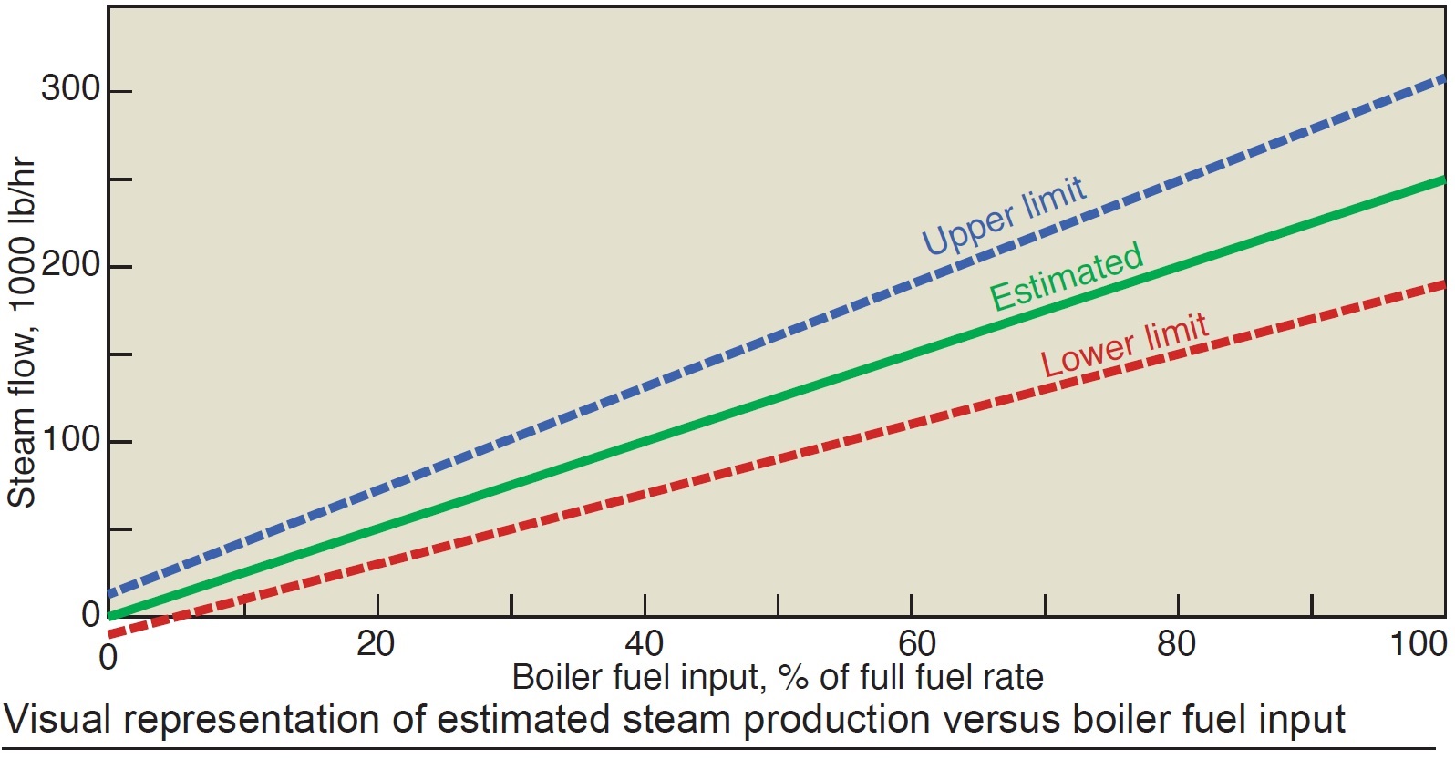
Regarding steam-flow measurement, Geismar uses a verification system to check reading accuracy. By modeling steam flow versus other operating parameters, staff can predict accurately what the steam flow should be. If measured steam flow varies from the predicted value by too much, the drum-level control system alarms and the predicted steam-flow value is used in place of the measured value.
For the plant’s conventional fired boilers, steam flow can be predicted accurately using fuel flow (figure). For the cogen unit with the unfired HRSG, steam flow is predicted based on gas-turbine output (megawatts), and for the cogen unit with the fired HRSG, on a combination of gas-turbine output and fuel flow to the duct burner.
All of these calculations are made by the DCS. So, it makes no difference if the steam-flow measurement is the result of a problem with the flow, pressure, or temperature transmitter because the predicted steam-flow value is close enough for the system to continue accurately controlling drum level.
Regarding the BFW flowmeter, this instrument is the most critical in the drum-level control scheme because the drum-level control is actually feedwater control used to regulate drum level indirectly. Geismar installed logic that monitors the difference between the measured feedwater flow and the feedwater flow setpoint. This difference normally is very small. A large difference indicates a problem (either measurement error or feedwater valve issue) and the control scheme would transition from a 3-element arrangement to single-element (drum level), thereby removing the faulty feedwater reading from the control scheme altogether.
For the drum pressure transmitter, staff removed the “default-to-manual” logic that occurred when an I/O error was received, defaulting the drum-pressure reading to a constant value typically seen during normal operations.
Results. The site lost all six of its steam producers (two cogen units and four conventional boilers) during a very hard freeze in January 2018. Reason: Low drum levels caused by a combination of the failure scenarios described above—inaccurate steam-flow measurement, inaccurate BFW flow measurement, and controller default to manual attributed to failed instruments.
Following the freeze event, the changes noted above were made and deficiencies in the heat-trace system were corrected. Since that time, the boilers have successfully weathered instrument failures on the steam-flow reading, drum-pressure measurement, and drum-level measurement.
A few instruments were affected during the hard-freeze event in February 2021, but the improvements made were sufficiently robust to keep all steam producers in service.
Shared by David Lucier, founder and GM, PAL Turbine Services LLC
Use correct names of gas-turbine components to avoid confusion
Components and auxiliary systems for GE gas turbines have specific names. It is important to use correct names when communicating with the manufacturer or service companies to be sure you’re understood. For some, it may be like learning to speak a new language, which can be called “GE-ology.”
In 1961, GE introduced the gas-turbine Packaged Power Plant. The company’s first PPP was the MS5001—a/k/a Frame 5. When introduced, the engine was designed to produce 12 MW, a rating that prevailed throughout the first half of the sixties. During the second half of the decade, demand for emergency power was unprecedented, with investor-owned electric utilities and municipalities placing orders for dozens of PPPs.
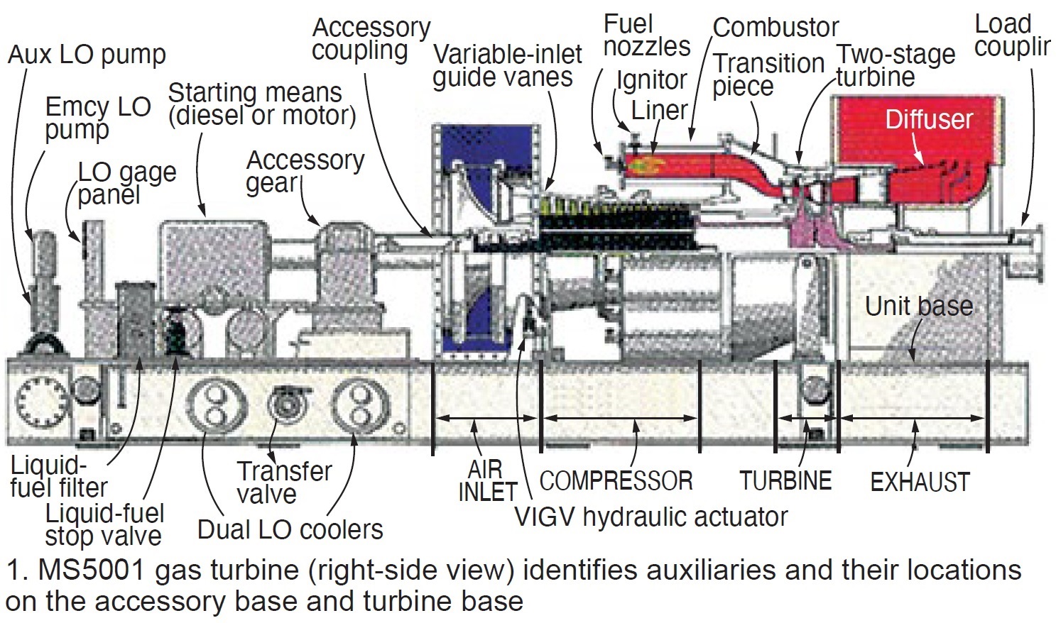
The PPP design had most of the auxiliary fluid systems located on the accessory base with the goal of minimizing installation and startup times. It included the following:
- Accessory gear with water, oil, and fuel pumps, and atomizing air compressor.
- Lube-oil (LO) tank integral to the I-beam base with oil pumps, coolers, filters, pressure regulators, etc, inside the base or above it.
- Hydraulic supply system using lube oil to provide high-pressure fluid for operating servo valves and the ratchet rotor-turning device, and for enabling clutch engagement. Earlier systems for clutch operation, diesel actuation, and ratchet engagement relied on high-pressure air.
- Fuel system components also atop the base included the following:
- Liquid-fuel pump and flow divider.
- Gas-fuel stop and flow-control valve.
- Cooling water system installed in the roof with radiators and fin-fan drive.
- Starting device (diesel engine or cranking motor) was on-base with jaw clutch.
Fig 1 presents the right-side view of a gas turbine showing its auxiliaries and their locations on the accessory and turbine base. Fig 2 provides an isometric view. Most everything needed to operate the turbine is tagged. Some of the components not visible in Figs 1 and 2 include the fuel pump, 12-position fuel pressure selector valve and gage for each combustor, and liquid-fuel flow divider. Other devices that would be installed on the gas turbine include two compressor bleed valves, two igniters (a/k/a sparkplugs), and ultraviolet flame detectors.
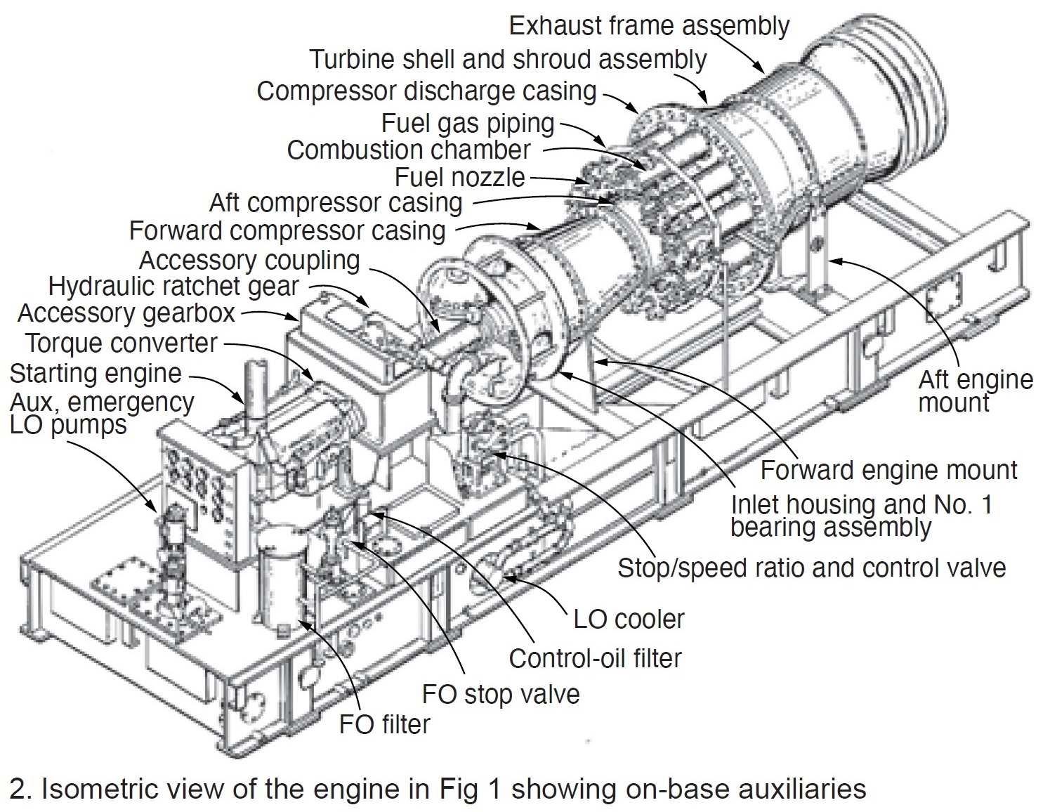
Given the availability of a cured concrete foundation onsite, PPP installation typically took less than two months. Bear in mind that this was the first time the gas turbine was “introduced” to its generator, load gear, control cab, generator breaker, and protective devices—all manufactured at GE facilities in other cities.
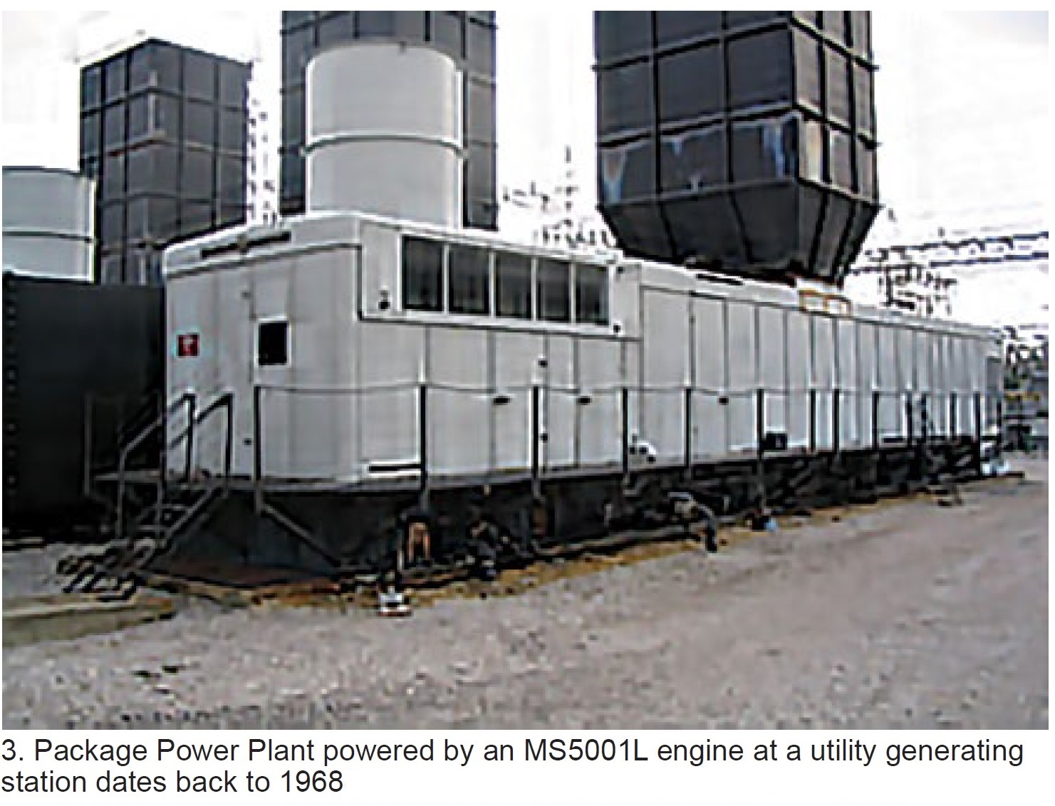
A typical PPP (Fig 3) shows the accessory base (left), gas turbine and exhaust (center), and generator (far right). This configuration of major components prevailed for over 50 years in the design of most GE Frame 5 and 6 gas turbines—even those installed inside buildings.
A simple way to check gas-turbine performance
GE gas turbines installed in electric generating plants from the mid-1960s to the late 1980s operate infrequently today—typically confined to peaking and emergency service—given the availability of more-efficient machines for mid-range and baseload duty. However, when your legacy engines do run it is good to know if they are operating “up to snuff.”
There’s an easy way to do this knowing compressor discharge pressure and exhaust temperature, calculating the pressure ratio, and plotting this information on the OEM’s performance graph provided in the plant’s Control Specifications.
Below are the steps involved, using the MS5001L gas turbine to illustrate the process. These so-called 5L turbines were designed with NEMA (National Electrical Manufacturers Assn) ratings of approximately 15 MW for a compressor inlet temperature of 80F and site elevation of 1000 ft (14.17 psia).
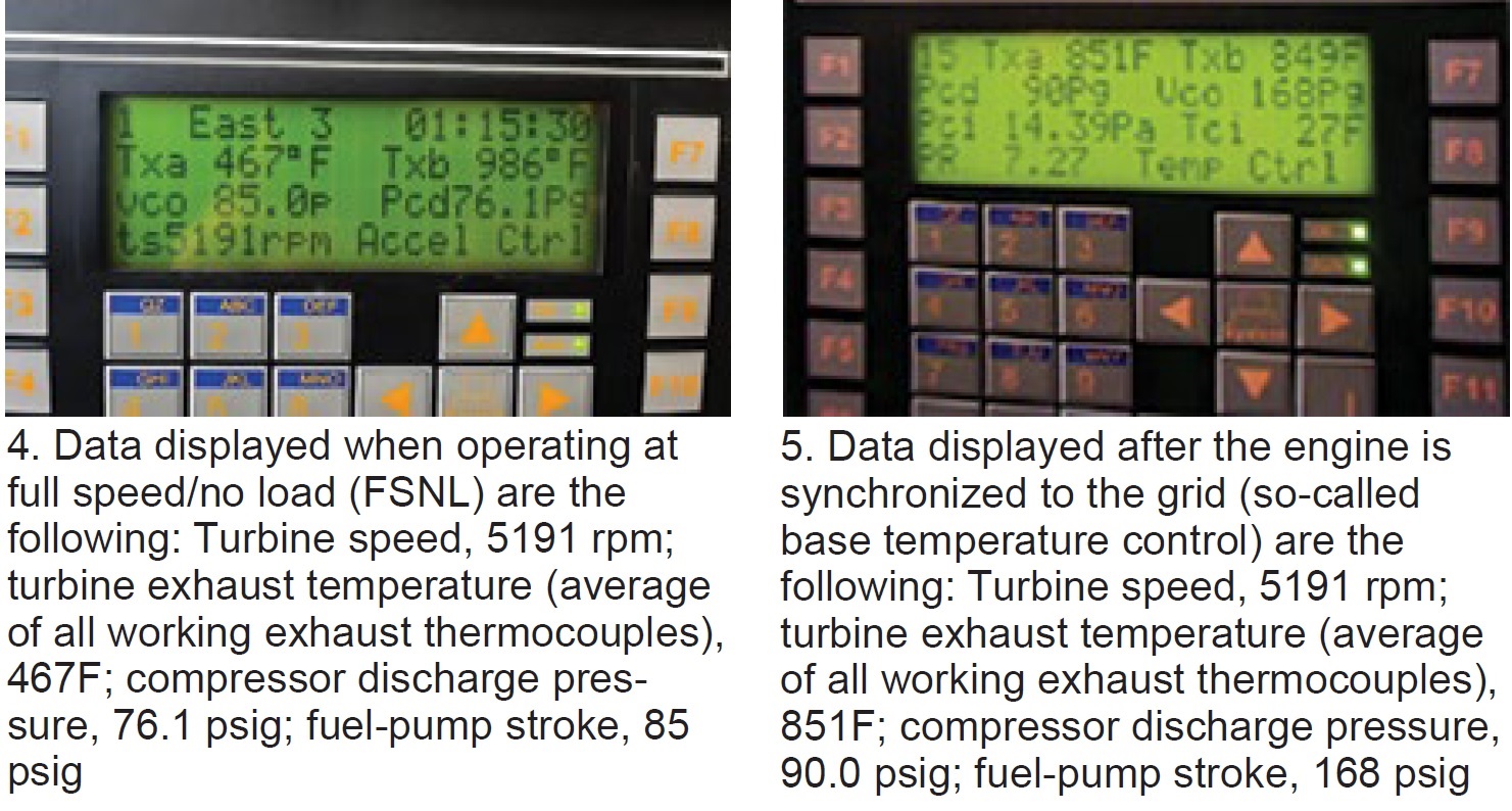
First, access the following information from the control system display (Fig 4) at full speed/no load (FSNL):
- Turbine exhaust temperature (TXA).
- Compressor discharge pressure (PCD).
- Fuel-pump stroke reference (VCO).
The data are repeated in the caption to facilitate readability. Given the compressor inlet pressure is 14.39 psia from site data (if not available, use the standard 14.7 as its impact will be minimal, especially for legacy turbines), the pressure ratio (CPR) can be calculated as follows:
CPR = [76.1 (PCD) + 14.39] ÷ 14.39 = 6.29.
Since speed is constant at FSNL, in preparation for the generator to supply power to the grid, consider that a new operating “plateau” has been reached: synchronous speed. Thereafter, the data of interest increase in direct relation to fuel flow to the combustors (Fig 5).
Again, the data are repeated in the caption to facilitate readability. As for the previous calculation, the compressor inlet pressure is 14.39 from site data and the pressure ratio at baseload is the following: CPR = [90 (PCD) + 14.39] ÷ 14.39 = 7.25.
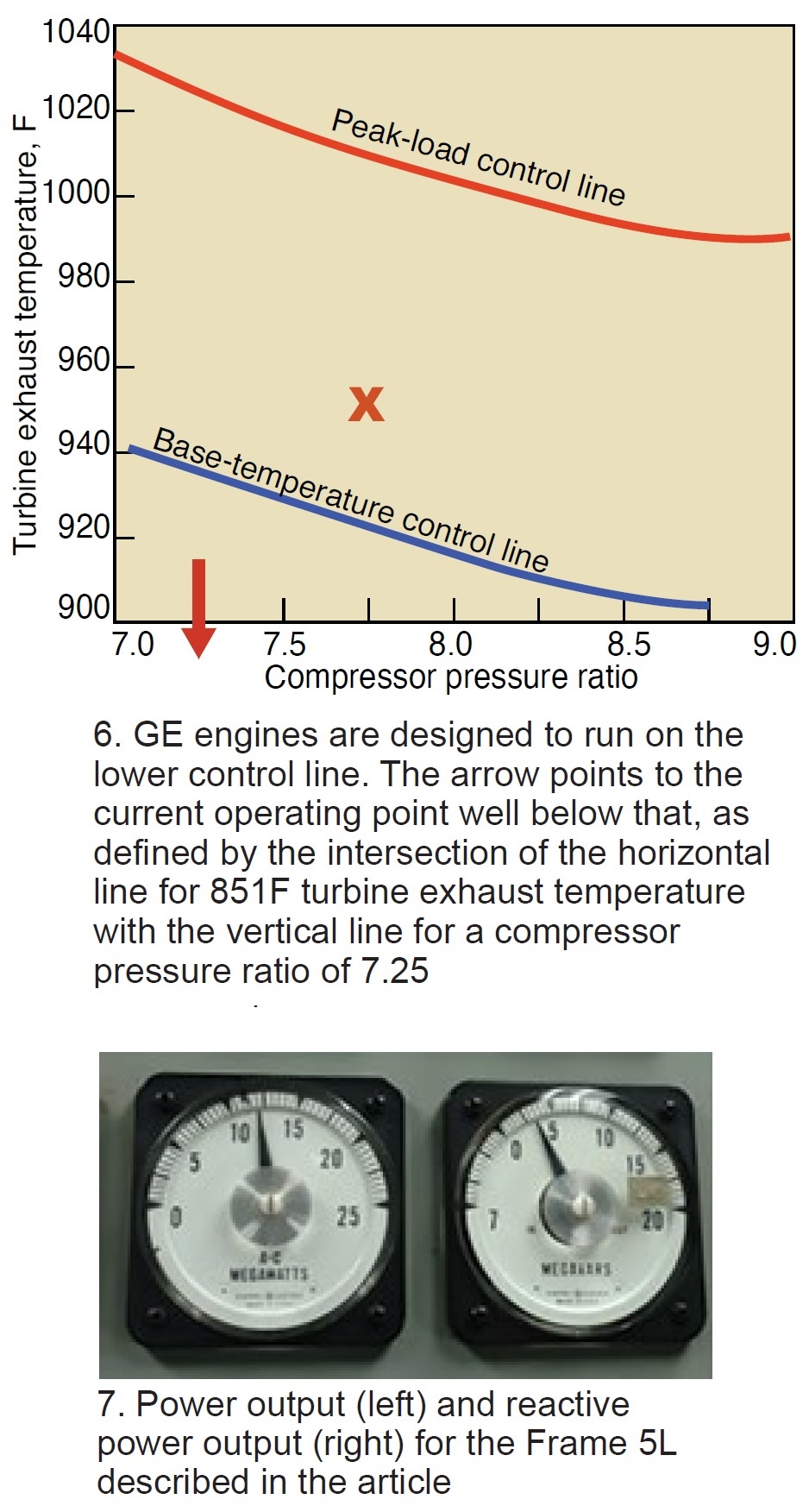 Next, go to Fig 6 and plot the average exhaust temperature at full load (851F from Fig 5) against the compressor pressure ratio of 7.25 at baseload. That point occurs well below the base temperature control line, as the arrow indicates. Important to note that GE engines are designed to run on the lower control line. When operating below this line, the unit is under-firing—that is, performing below the design rating. Fig 7 illustrates this with a power output of 12 MW, lower than expected with 3.5 MVAr of reactive power.
Of course, you might choose to operate slightly below the engine’s design rating to maintain its reliability and minimize wear and tear, given the unit’s age. You can do this by adjusting the fuel regulator to reduce exhaust temperature.
Performance analysis. For the Frame 5L example, power production increases from 0 MW at FSNL to 12 MW, because fuel flow to the compressor increases during the ramp up in output. During this transition, compressor discharge pressure goes from 76.1 to 90 psig—a rise of only 13.9 psi, which is considered low and indicative of something being wrong. Here’s what to check:
- Fouled compressor, typically caused by poor-quality ambient air. Examples: Soot deposits are common in gas turbines downstream from a refinery or chemical processing plant, salt deposits in units located within five miles or so of an ocean or other body of saltwater. Action to consider:
- At FSNL, inject Carbo Blast or equivalent for dynamic cleaning of compressor blades. Veterans may recall walnut shells being used for this purpose back in the 1960s and 1970s.
- Partially opened compressor bleed valves. During startup, CBVs should be fully closed at about 75% of rated speed and never leak. Action to consider if your CBVs leak: Disassemble, inspect, clean, and lap sealing surfaces as required.
- Leakage at the compressor discharge—such as missing transition-piece side seals or at another unwanted opening causing a pressure loss. Action to consider: Bring in a qualified borescope inspection team to look for passages for leakage.
- Cracking or erosion of one or more first-stage nozzles. If the trailing edges of nozzle partitions are worn or eroded, the backpressure on turbine buckets will drop, reducing power output. Action to consider: Conduct a borescope inspection of first-stage trailing-edge partitions.
Finally, consider the case where power output increases from FSNL to the 15 MW designers intended for the Frame 5L. For these conditions, the expected average turbine exhaust temperature would be approximately 950F. Also, compressor discharge pressure should increase by nearly 20 psi—from 76.1 psig (refer back to Fig 4) to the 95 psig expected based on the NEMA rating for this machine with a clean compressor. The compressor ratio for the Frame 5L at NEMA conditions and using the same calculation presented earlier, would be 7.72.
Final step: Plot the 950F exhaust temperature and 7.72 pressure ratio on the Fig 6 chart (X marks the spot), noting that it is above the control line. This means the unit is over-firing and the exhaust temperature should be reduced by 20 deg F or so to minimize the wear and tear on first-stage nozzles.
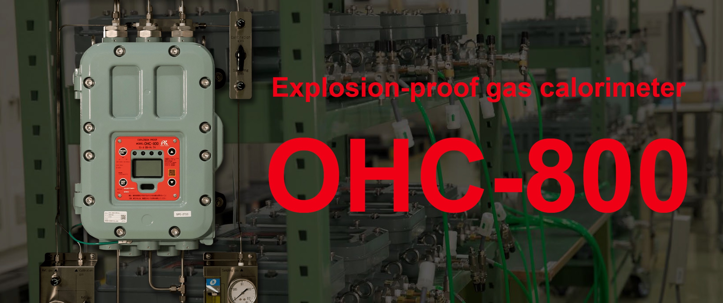
All in one explosion-proof gas calorimeter which features Continuous measurement, High accuracy & High-speed response.
Continuous measurement
By combining an optical sensor and a sound velocity sensor to perform unique calculations, the system is not affected by interference from gases that do not have heat content, such as N2, CO2, and O2. OIML R140 Class A equivalent (currently under application)
High accuracy
Measurement data can be updated every 0.25 seconds, a feature which is not possible with gas chromatography. Robust design for all measurement environments eliminates the risk of measurement outages.
High-speed response
T90 Fast response time of less than 5 seconds. Responding to sudden changes in calorific value.
| View more information |
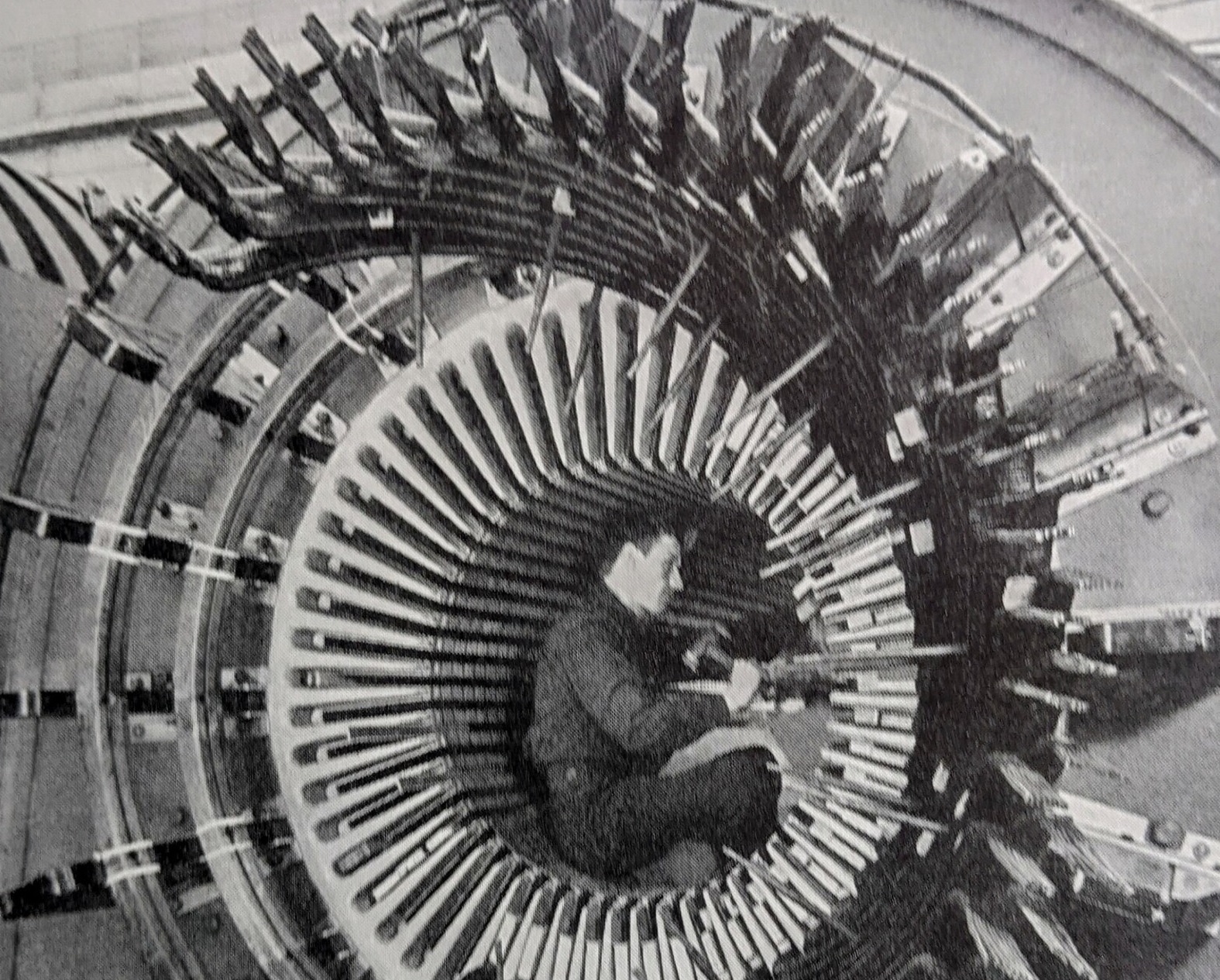
By Clyde V Maughan, Maughan Generator Consultants (retired)
This historical perspective on turbine-driven generators, in four parts, is based on Clyde Maughan’s recollections from a 72-year career in turbine/generator design, manufacturing, and service—half that time with General Electric Co, the remainder as an independent consultant.
 Having joined GE in 1950, and having worked closely with the “old timers” of that day, his direct knowledge base goes back into the teen years of the 1900s—a span of over a century. No guarantee is offered that all the information is exactly correct, but the essence should be acceptably close to give a general understanding of the difficult evolution to the present designs of generators.
Because the major OEMs of the day kept pretty close (informal) watch on each other, the industry was generally well informed on the designs, and troubles, of each. Thus, the information here on non-GE machines should be reasonably accurate.
The focus of this article is on the materials and structural configurations, and associated service issues, of generators installed from about 1960 onward, with little insight provided as to why specific materials were selected or why the configurations were needed.
This information should be of particular value to owner/operators of GE Frame 5, 6B, and 7B-EA gas turbines, some of which date back to the late 1950s, as well as to users at combined cycles equipped with steam turbines repowered from mid-century coal-fired powerplants.
Summaries of recent presentations by owner/operators and vendors at meetings of the Generator Users Group, as well as of the Steam Turbine Users Group, the Combined Cycle Users Group, and the organizations serving the legacy Frame 5, 6B, and 7B-EA GE gas turbines are only a mouse click away in CCJ No. 71.
Generators Table of Contents
Intro: Generators, a brief history
Part 1: Electrical insulation systems
Part 2: Winding support systems
Part 3: Generator cooling methods
Stator windings
Groundwall insulation. Before the turn into the 20th century, insulating materials were natural products: shellac, cotton, paper. The rudimentary stator-winding designs were at low voltage and low temperatures, and apparently functioned fairly well as long as duties were kept sufficiently low. With inevitable trends to larger generators, with higher voltages and higher thermal and mechanical duties, much better materials were required.
Somewhere around this time, mica flake was discovered to have remarkable electrical and thermal properties. But still with shellac, cotton, and other relatively primitive materials
incorporated in the systems, troubles continued. By the mid-teen years (1915) it was discovered that by using a vacuum-pressure cycle, mica/cotton tapes could be impregnated with a hot asphalt compound to obtain a major electrical duty improvement. Asphalt/mica systems served the industry well for 35 years.
About 1950, Westinghouse developed the first “hard” groundwall system—Thermalastic, a polyester resin system. This was a remarkable accomplishment, particularly in view of the relatively primitive resins available at that time.
Shortly thereafter, all OEMs developed hard groundwall systems, including the following: Micapal (a polyester-like epoxy), Micapal II (a true epoxy), Thermalastic-Epoxy (a true epoxy), and Micadur.
All these insulation systems rely on mica because of its remarkable partial-discharge (PD) resistance properties. (No man-made product begins to have the incredible PD resistance of mica. Bear in mind that PD is inevitable in the rectangular configurations of stator bars.)
But mica brings with it poor mechanical properties—brittle, non-extensible, no mechanical strength whatever in cross-grain tension. Thus, stator groundwall insulation systems remain with limited mechanical properties, and when subject to bending stress—short-circuit forces, for example—fracture about like glass.
In the 1990s, a global vacuum pressure system for the stator winding was introduced by Siemens. The GVPI system has major cost advantages and is used extensively on indirect cooled designs. Many of those stators have been produced and quality has been good. But if failure occurs, rewind is difficult.
Groundwall voltage stress levels. The stress on the groundwall has a dramatically important impact on electrically related problems associated with stator windings. The significance of this impact is better understood by realizing that duties associated with stress have been found to be in the range of a seventh- to 11th-power function of the stress level. For example, if the design stress is increased by 20%, the duty increases by 1.2 to the ninth power, or about 500%. Recognizing this attribute, design engineers have increased stress relatively slowly over the years.
By 1950, the stress level on the asphalt-insulation systems was about 45 volts/mil (vpm). With the advent of hard (polyester-type) systems, the stress level was increased to around 54 vpm. By the mid-1960s, improved (epoxy) systems were being used, and the stress levels increased to the low 60s. Today, stress levels exceeding 90 vpm are being used. The magnitude of 90/60 to the ninth power is about 3800%, an increase hard to contemplate. Expect electrical groundwall failures to become more common in the future.
Problems associated with groundwall voltage stress. The predominant problem associated with groundwall stress, PD, sometimes is incorrectly called “corona.” The stress gradient within the groundwall results in electrical breakdown in the tiny voids in the groundwall. These mini-arcs tend to eat through any insulation system without the PD resistance of mica.
If the outside surface of the groundwall is not adequately grounded, there will be discharges of much higher energy. This, in turn, can result in surface PD. This condition, captured in Fig 1, appears very serious, but careful examination and scraping with a thumbnail would find little or no penetration into the mica groundwall.
Nevertheless, it cannot be ignored, especially in air-cooled generators, where ozone generation will be significant. Also, there is no assurance that penetration of the mica may not eventually begin.
Furthermore, the increased capacitive energy increases the duties on endwinding grading systems—for example, at the junction between end-arm grading and slot grounding paints (Fig 2).

The damage at this junction is often regarded as PD but is actually burning because of an inadequate interconnection to carry the capacitive current from the end-arm grading system.
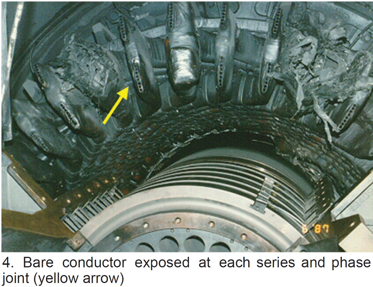 Where non-mica insulation has been used in endwindings, reliability sometimes has been seriously compromised. Example: Fig 3, where phase joints were insulated with non-mica potting compound and Nomex.
A large number of generators rely on physical spacing to hold the voltage stress. So long as the surfaces are clean, operation is satisfactory. But when surface contamination occurs, massive arcing can occur (Fig 4).
A final observation: Stator-winding electrical-arc damage normally accompanies stator-winding failure, but the actual root cause is usually mechanical—for example, vibration, fracture, foreign object, and contaminants. To this point in time, generator failures caused by purely electrical duties are uncommon.
Bare bar stranding. Because eddy-current losses would immediately melt a stator bar made of solid copper, a stranded design has always been required. On coil windings, no special transposition is needed—that is, the top and bottom bars of a coil automatically tend to cancel out the voltage difference between the top and bottom strands in the half-coils. (In this article, the term “bar” is used to define a half coil. For convenience the term “bar” is used almost exclusively.)
On bar windings where it is usual to solidly connect all strands at each end of the bar, this cancelation of radial flux difference in the slots does not occur. Very early (in 1912) a Swiss engineer, Louis Roebeled, invented an elegantly simple way to construct this transposition on bars.
His invention, the Roebel bar, was no great scientific discovery, but rather a remarkably simple way to accomplish a very difficult task—construct the transposition. It is so manufacturing friendly the Roebel transposition system is universally used by all OEMs, with the exception of those few who have manufactured smaller bar windings without consolidating the strands at the ends of the bars.
The standard Roebel transposition effectively compensates the radial flux-density gradient in the slot portion of the winding. But on larger generators of non-coil design, the radial flux gradient in the endwindings becomes sufficiently large to cause problems—a concern automatically eliminated in coil windings.
Several approaches have been used here. The simplest is that of a 540-deg Roebel rotation in the slot. (Note that Roebeled’s invention was single 360-deg rotation.) The somewhat complicated 540-deg rotation performs a correct compensation in the slot while inverting the strands at the two endwindings beyond the core.
Another approach for endwinding radial-flux compensation has been to sub-group the bar strands into bundles of strands; bundles may range from as few as one strand to as many as 14, or more. These “bundles” are maintained throughout the entire phase belt. Bundle design greatly complicates the winding manufacturing process and has been accompanied by numerous service problems (Fig 5).
Strand insulation. A small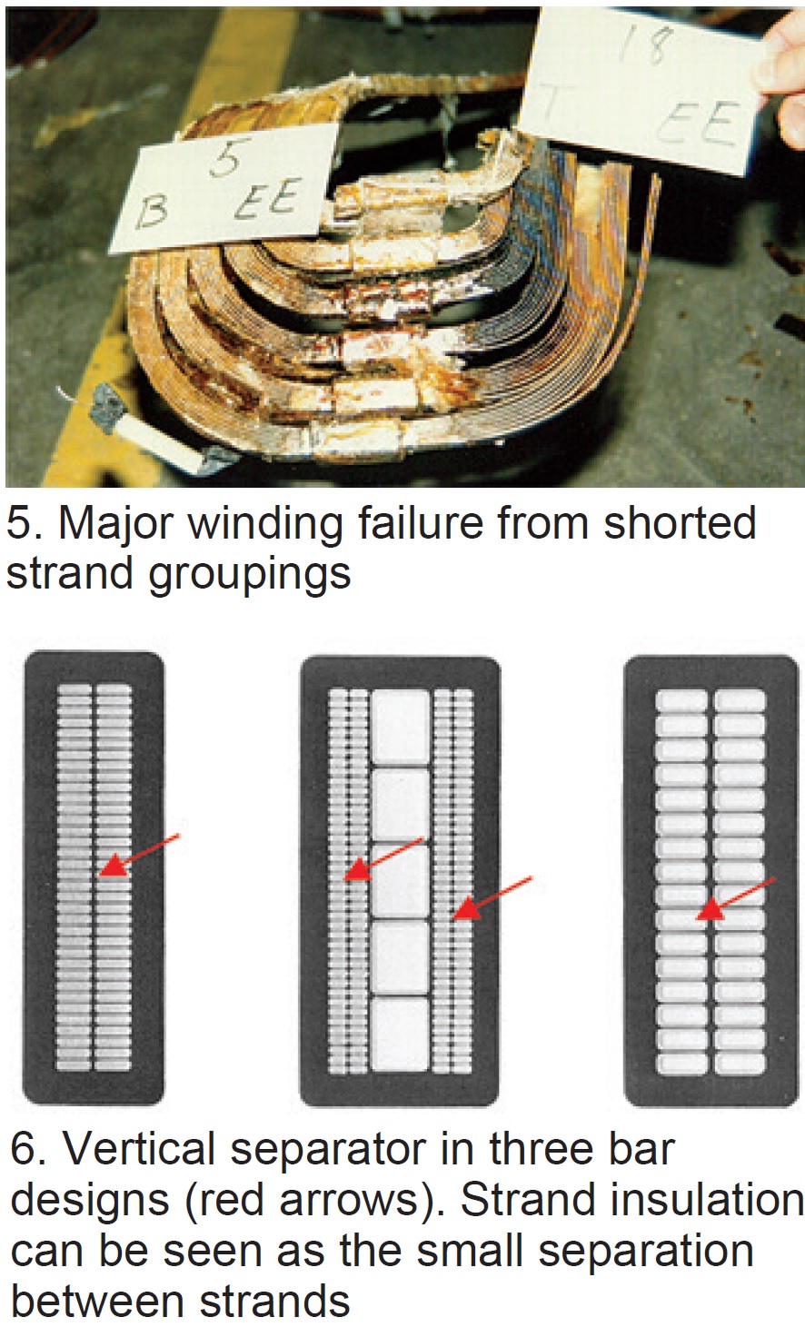 voltage exists between adjacent strands, probably always less than 1 volt, and the strands must be individually insulated. Originally, cotton would have been used, then glass, and now commonly Dacron-glass. The last material is thin, typically 1 to 3 mils/side.
A higher voltage exists between tiers of strands. Here a “vertical separator” is inserted between tiers. The stress may be as high as 15 volts and the thickness may be about 15 mils (Fig 6).
Voltage grounding and grading. If the outside surface of the groundwall is not tied electrically to ground, PD will exist between the bar surface and ground. Consequently, a semi-conducting (low resistance) paint is applied to the outside surface of the slot portion of the bar (and usually about 2 in. beyond the slot at each end). If properly applied, and of good quality, this paint will eliminate the PD by grounding the outside surface of the bar insulation to the slot iron.
More complicated is the necessity to “grade” the voltage of the grounding paint at each end of the slot (Fig 7).
The engineering principles here are complex, but the mechanics are relatively simple. Originally, asbestos tape was applied for a distance of perhaps 7 to 12 in. beyond the end of the slot grading paint, depending on winding voltage. In the 1960s, the industry went universally to silicon carbide—both to eliminate the hazard of asbestos, but because silicon carbide offers a more effective approach to grading.
Series/phase joint insulation. It is common to insulate these joints with mica tapes. Beginning about 1970, some designs used synthetic resins inside a non-metallic box. This is a marginally acceptable method at the phase connections because the voltages here are high.
Physical spacing also has been used by some OEMs. This design approach is safe—providing the creepage paths remain uncontaminated, and providing there is not a conductive plasma resulting from arcing of a failing electrical connection. In the event the insulating capacity is violated, a “ring of fire” can result (refer back to Fig 4).
Field windings
The duty differences between stator and field insulation systems could hardly be more different. On stator windings, the voltages are high but the mechanical stresses are low. On fields, the voltages are low, less than 700 Vdc, but the mechanical duties very high, in the order of thousands of psi.
Because of the low voltages, and the need for direct contact between cooling gas and winding copper, isolation using electrical creepage surfaces is common. So long as the insulation remains in place and does not become contaminated with conductive materials, the systems tend to perform well. But because the mechanical duties are high, problems can occur. They typically result from fracture, cut-through, and shifting of location of the insulation components. Result: Service problems relating to insulation failure are common on fields.
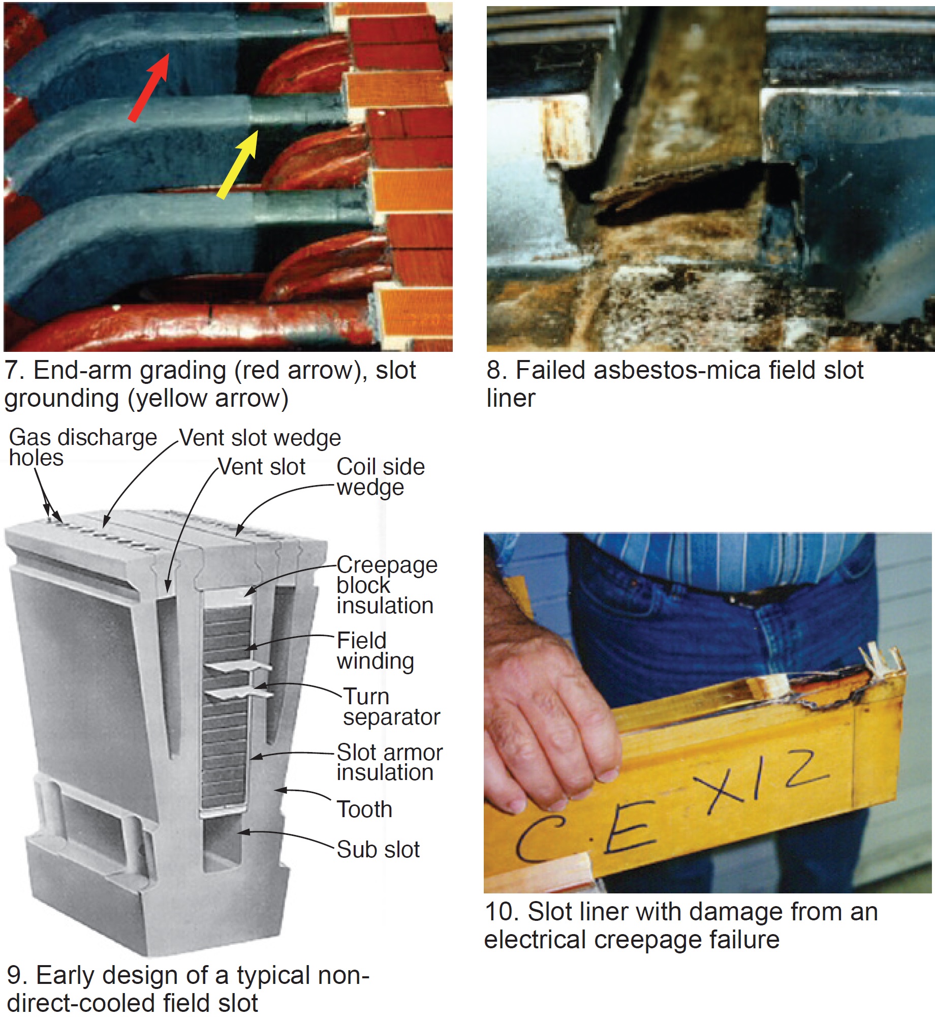
Slot liners (ground insulation). Until about 1960, ground insulation for coils consisted of enclosing the coil with cotton or asbestos cloth for mechanical stability and mica flake for insulating properties (Fig 8).
This composite structure served adequately because of the low-voltage stresses. More recently, Nomex, glass/epoxy fabric, and composites of glass/epoxy and Nomex have become popular. Generally, this ground insulation is in a U-shape, closed at the top by a creepage block (Fig 9). These ground insulation systems have been subject to failure primarily because of contamination, fracture, migration, and cut-through (Fig 10).
Turn insulation. The voltage between turns is low, typically 1 to 5 volts. Historically, mica tape was used, but since about 1960, thin glass/epoxy laminate has been in common use for turn insulation. So long as physical spacing is maintained, turn shorts are unlikely. However, the integrity of the space can be violated by fracture or migration of the material, or by conductive contaminants bridging the spacing. Failure of turn insulation is relatively common.
Endwinding insulation. Under the retaining rings, sheet laminate of heavy-weave asbestos cloth and mica was the historic insulation system. Again, around 1960 transition was made to a laminate structure of heavy glass cloth and epoxy resin. The laminate is degraded somewhat when the 300C retaining ring shrinks down onto the epoxy glass; however, the materials used are sufficiently thick and thermally stable that the electrical strength remains adequate for single use.
Insulating-block material is used to hold coil shape and to insulate the axial locations of the endwindings, as shown later in Fig 15.
Generators Table of Contents
Intro: Generators, a brief history
Part 1: Electrical insulation systems
Part 2: Winding support systems
Part 3: Generator cooling methods
Stator windings
Slot support systems. From the beginning, stator bars were held in the slots by wedges of treated paper or hardwood. The electromagnetic forces were low (almost non-existent), the groundwall insulation was soft, and bars had little cause to vibrate. The wedges held the bars in the slots and kept them from falling out of the slots in service, and perhaps kept the bars from being thrown out of the slot in the event of a sudden short circuit.
The wood materials used during the industry’s first 50 years were satisfactory. But wood inevitably shrinks, and the resulting looseness of wedges was a concern. With the advent of man-made resins, in the 1950s transition was made to resin/cotton, resin/asbestos, and then resin/glass materials.
But when hard groundwall systems were introduced in the 1950s, a shocking condition surfaced—bar vibration. (You could walk by the generator and hear the noise from the impact of the bars in the bottom of the slots.) Needless to say, windings failed relatively fast, from mechanical wear and impact, and from vibration sparking. An immediate fix was implemented: Wedging with tight downward pressure on the bars.
This electromagnetic force (EMF) essentially is all radially downward in the slot, but if radial clearance existed in the slot, the bars would bounce off the bottom of the slot and vibrate vigorously. Also, if excessive side clearance existed, the bars would rattle in the slot.
Relatively simple wedging systems were satisfactory on indirect-cooled windings, but the slot EMF on the direct-cooled windings was much higher, and vibration recurred. GE solved this situation by adding side pressure springs (Fig 11).
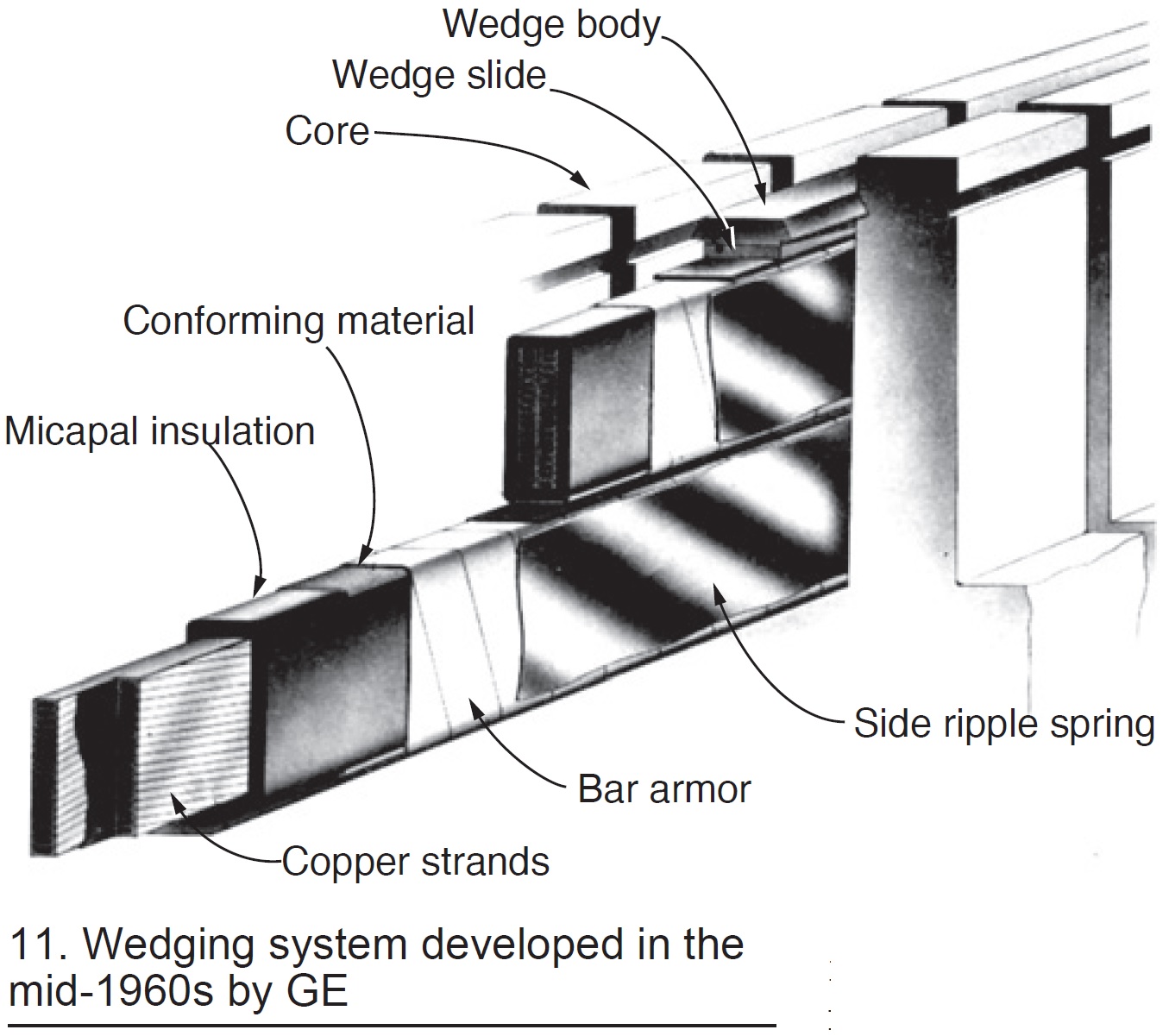
But most other manufacturers continued to rely on side packing and tight wedges. Finally, the industry added the radial pressure spring almost universally on large generators.
Slot bar vibration incidents continue to occur. But, in general, if the wedging system remains tight vertically, if clearance does not exist under the bottom bar, and if excessive side clearance is not permitted, problems are unlikely.
Endwinding support systems. In the early years, the endwinding EMF was so low that almost anything was going to be alright. The top and bottom bars in the endwinding, if tied together, form a rather strong mechanical structure. It remained primarily to support the bars (or coils) during installation.
The parameters relative to slot wedging and endwinding support have little in common. The endwinding EMF is lower but still substantial—roughly one-third to one-half that of the slot forces. Because the opportunities for supporting the bars in the endwinding are minimal, endwinding vibration has been more difficult to successfully address than slot vibration.
 Also, until recently there has not been available instrumentation to safely and accurately measure magnitudes of in-service endwinding vibration. Design engineers have not had tools to directly assess the success (or failure) of their new designs. Thus, engineers have had to rely on intuition and best judgment in producing new designs, and await accumulation of service experience to determine if the design change was successful.
However, as generators increased in size, the EMF became so great that endwinding vibration became ubiquitous. Starting about 1960, OEMs went into major development programs, spending millions of dollars developing designs that would hold the extremely high sudden short-circuit forces as well as the significant normal operation forces.
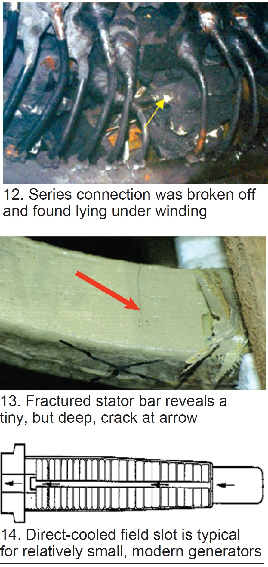
In spite of these huge OEM expenditures, endwinding support remains an ongoing problem. Parts become loose and wear holes in groundwall insulation. Connections become resonant and break off or fracture the bar (Fig 12).
Sudden short circuits can crack bars. It is doubtful that any design today can experience a worst-case short circuit without damage to the bars in the endwindings (Fig 13).
Stator endwinding concerns will remain into the future, particularly from local or general loosening of the systems allowing component wear to occur and resonances to develop. However, it can be expected that with the new capability to safely and accurately measure endwinding vibration, the designs will improve and reliability will increase.
Field windings
The mechanical forces on field windings are extremely high—resulting from up to 8000 g of centrifugal force acting radially at the tops of the slots. Metallic wedges can hold copper coils in the slots, and there are stable insulating materials that generally can function acceptably against these steady-state radial forces. It is the cycling duties resulting from start/stop and load changes that are the primary source of problems.
Winding copper is a main contributor to service issues. Copper has poor mechanical properties, even at room temperature. Yield strength is low, fatigue properties poor. At elevated temperature—above about 130C—these marginal properties begin to fall off. Unlike steel, copper only can be work-hardened; it cannot be hardened by quenching. With such poor mechanical properties, and high mechanical duties, engineers have been challenged to design support systems that successfully restrain copper coil dimensions and prevent their movement in position.
An indirectly cooled slot support design was shown earlier in Fig 9. In this design, heat losses must pass through insulation and forging iron to be removed by the flow of cooling gas. These indirect-cooled designs were used until direct cooling was required for higher generator outputs, starting around 1960. A typical direct-cooled slot is shown in Fig 14.
Electrical isolation in all field designs relies on “creepage” (voltage tracking over an insulated surface) and on “puncture” (voltage penetrating directly through an insulating material). Creepage isolation is used much more on the directly cooled windings, which makes them more vulnerable to contamination.
The radial blocking (red arrow) attempts to prevent both coil distortion and axial movement (Fig 15). Axial blocking (yellow arrow) primarily attempts to prevent coil distortion. But because the coils are not blocked continuously (to allow for cooling gas flow), and because of copper’s poor mechanical properties, distortion is common (Fig 16).
Because of the poor high-temperature properties of copper, significant over-temperature can result in fatal changes in coil dimensions. The result will be an immediate forced outage.
As windings lose position, the insulating materials tend to wear and crack. Grounds and shorted turns/coils result from damaged and contaminated insulation (Fig 17).
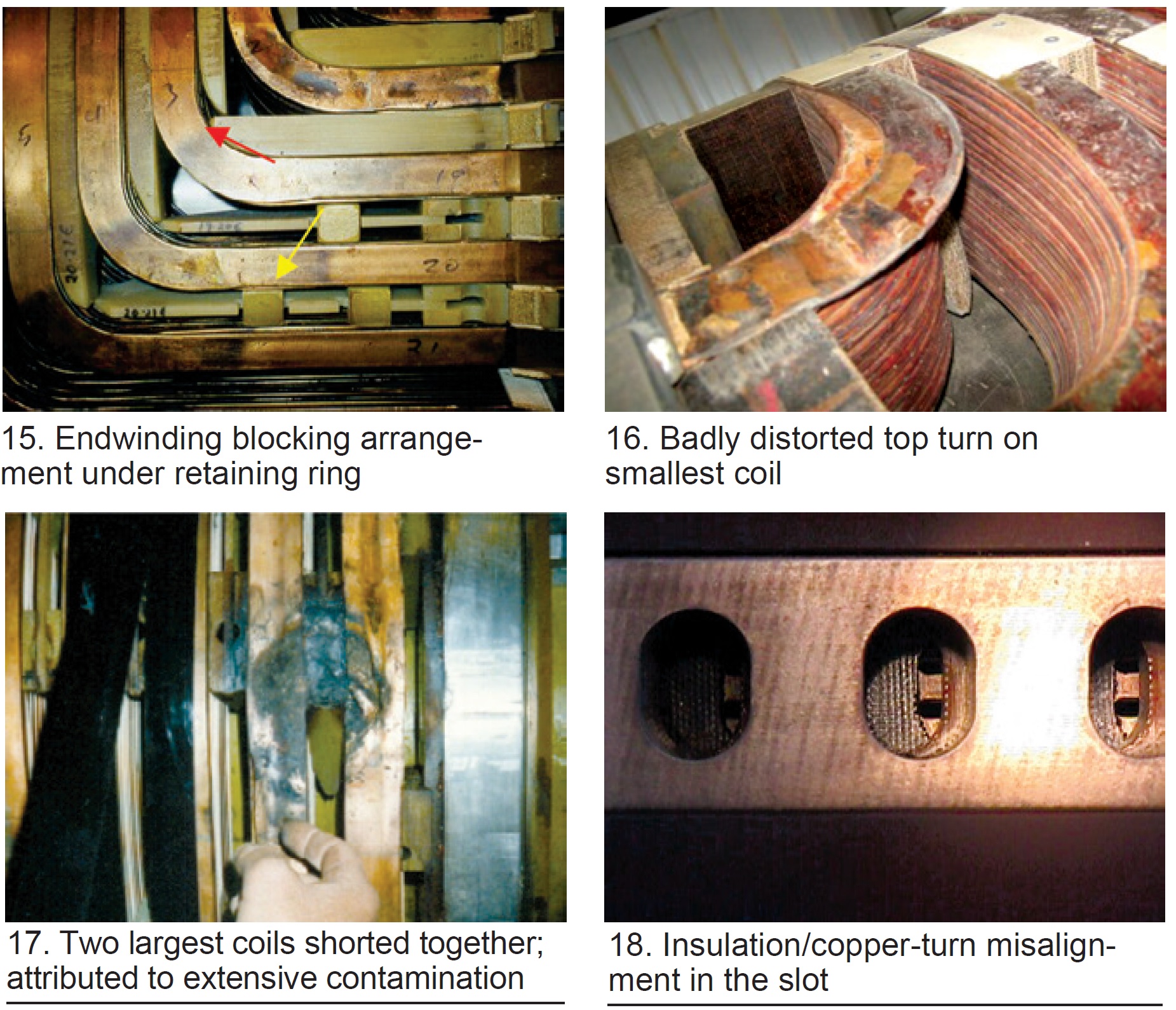
Further complicating reliable field operation is the need for uniform cooling of the coils in the rotor body. In Fig 18, the turn insulation and/or top creepage block have/has shifted axially out of correct location. This partial blockage of some slots and not others will result in bowing of the field (acting as a bimetallic strip). The resulting bow will cause a “thermal unbalance vector,” and as it grows over time, may force attempts to rebalance the field. If the conditions continue to deteriorate, eventually a field repair or rewind will become necessary.
Generators Table of Contents
Intro: Generators, a brief history
Part 1: Electrical insulation systems
Part 2: Winding support systems
Part 3: Generator cooling methods


