![]()
Background: Legacy Turbine Users Group
The Legacy Turbine Users Group (LTUG), formed by Power Users earlier this year to facilitate the transfer of knowledge among members of the Frame 5, 6B, and 7EA Users Groups, greatly benefits owner/operators of these engines. With the number of experienced O&M personnel in decline because of staff reductions and retirements, it makes good sense to aggregate the talent on both the user and supplier sides for all to share—especially given that these GE engines have “common” elements.
LTUG’s first annual meeting was conducted as part of Power User’s Mega Event, Aug 29 – Sept 1, 2022, at the San Antonio Marriott Rivercenter, which attracted more than 350 owner/operators. Several reports on that conference are forthcoming. Here the editors review the backgrounds of the Frame 5 and Frame 6B organizations and salute BASF Geismar for its work in increasing the reliability of boiler drum-level controls. The 7EA Users Group, serving owner/operators of 7B-EA gas turbines, will be featured in the next issue of CCJ ONsite and include recent best practices from that fleet.
The GE Frame 5 is likely the most popular gas turbine ever produced for power and industrial applications. The first unit in this model series shipped 65 years ago from the OEM’s Schenectady (NY) shops and Frame 5s are still being built today—albeit by manufacturing associates abroad and at ratings about two and a half times those of the 12-MW models installed in the late 1950s and early 1960s.
Although more than 3000 of these machines have been sold over the years, the editors cannot find records of any formal user group meeting conducted since the millennium with the Frame 5 as its focus. Power Users believes this engine has value as a critical peaking asset and supported the launch of the Frame 5 Users Group as part of its 2022 Mega Event.
|
Frame 5 Users Group Steering committee, 2022 Josh Edlinger, Eastern Generation |
Frame 5s are, in a manner of speaking, “beasts,” and many don’t run very often. But that doesn’t mean they are immune to the problems found in more advanced machines that operate regularly and at higher temperatures.
Mike Hoogsteden, director of field services for Advanced Turbine Support, an industry leader in the conduct of borescope inspections to determine the condition of gas turbines and other assets, told the editors that a large majority of Frame 5 operators don’t perform semi-annual inspections, as do the large gas turbines running regularly. Depending on the run profile, a full compressor/combustion/turbine borescope inspection every one to two years probably makes best sense for many of these units.
Also recommended, and depending on unit designation, is an eddy-current inspection of all IGVs (fixed and variable) and the stage S0 or S1 stator vanes (first row of vanes). The EC scan would identify any cracks in the vanes.
Another location for a careful inspection is at the ninth-stage hook-fit, where component separation can be an issue. Recall that the thin ligament at the 10th-stage extraction slot forms the hook that holds one side of the ninth-stage stator vanes in place. It is susceptible to cracking that could allow one or more vanes to work free and go downstream causing major compressor damage (Fig 1).
If you are unfamiliar with how best to prepare for a Frame 5 borescope/EC inspection, contact your service provider. A couple of things Hoogsteden recommends: (1) For the combustion section inspections, provide access to every other one of the 10 cans via removal of the fuel nozzles; (2) gain access to the second row of turbine blades by availing access into the stack.
Hoogsteden then provided a flavor of what might be found with a borescope by sharing findings from three recent Frame 5 inspections. Engine A was a Model M, B a Model P, and C a Model N.
Engine A. The inlet section was found in relatively good condition, but there was rust and debris on the inlet floor. Inspector’s recommendation was to prep the floor for a two-part epoxy coating capable of withstanding regular water immersion.
The compressor section, accessed through the inlet bellmouth initially and later through the removed upper case, revealed partial liberation of the IGV tip shroud, causing significant downstream damage (Figs 2 and 3). An engineering review was recommended before repairing and restarting the unit.
The combustion section was in good condition; water wash residue was visible on the hardware. Combustion liners were accessed through the fuel nozzles in cans 3 and 7.
The turbine section, accessed via the combustion liners, also was in good condition. The exhaust section was not inspected.
Engine B. Rust and debris was found on the inlet floor of this unit as it was in Engine A. Inspectors accessed the compressor section through the inlet bellmouth, finding two stage S0 stator vanes had liberated at the 6 o’clock position (Fig 4) along with one R9 rotor blade (Fig 5). Result: Extensive damage throughout the compressor.
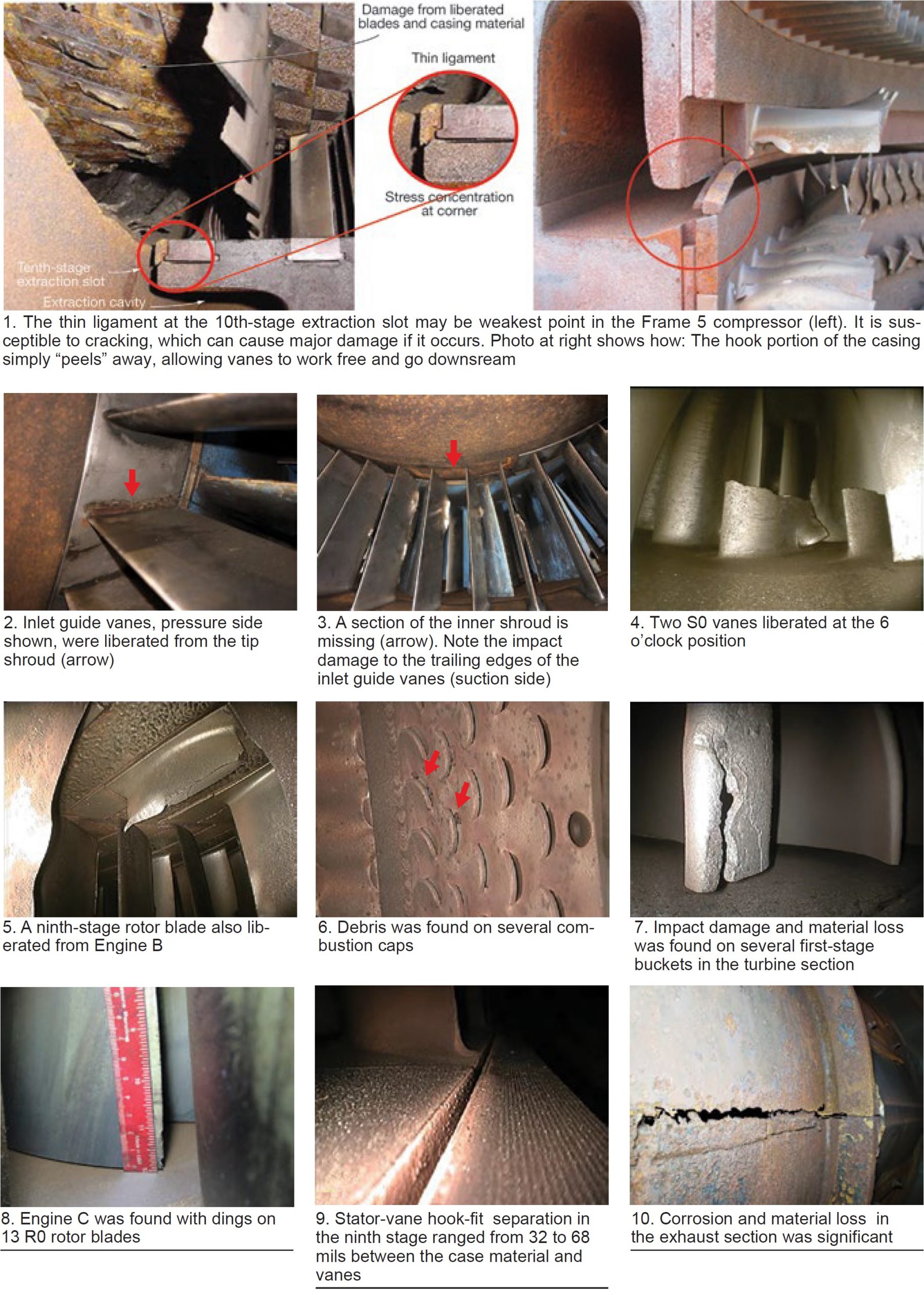
Combustion liners were accessed through the fuel nozzles, the turbine section via the liners and exhaust section. The combustion section was found in good condition except for some debris found in the combustion-cap air slots (Fig 6). Impact damage and material loss was suffered by a majority of the first-stage turbine buckets (Fig 7). Condition of the exhaust section was “good.”
Engine C. Access (1) to the compressor section was through the inlet bellmouth and the ninth-stage air extraction, (2) to the combustion liners via fuel nozzles and crossfire tubes, and (3) to the turbine section by way of the combustion liners and exhaust section.
Impact damage was found at the leading edges of 13 R0 rotor blades (Fig 8), the debris causing minor damage throughout the compressor. Stator-vane hook-fit separation was evident in stage 9, where the gap between the case material and stator vanes ranged from 32 to 68 mils (Fig 9).
The combustion and turbine sections were in good condition; however, there was inner-barrel corrosion with material loss and cracking in the exhaust-section diffuser vanes (Fig 10).