Stator windings
Slot support systems. From the beginning, stator bars were held in the slots by wedges of treated paper or hardwood. The electromagnetic forces were low (almost non-existent), the groundwall insulation was soft, and bars had little cause to vibrate. The wedges held the bars in the slots and kept them from falling out of the slots in service, and perhaps kept the bars from being thrown out of the slot in the event of a sudden short circuit.
The wood materials used during the industry’s first 50 years were satisfactory. But wood inevitably shrinks, and the resulting looseness of wedges was a concern. With the advent of man-made resins, in the 1950s transition was made to resin/cotton, resin/asbestos, and then resin/glass materials.
But when hard groundwall systems were introduced in the 1950s, a shocking condition surfaced—bar vibration. (You could walk by the generator and hear the noise from the impact of the bars in the bottom of the slots.) Needless to say, windings failed relatively fast, from mechanical wear and impact, and from vibration sparking. An immediate fix was implemented: Wedging with tight downward pressure on the bars.
This electromagnetic force (EMF) essentially is all radially downward in the slot, but if radial clearance existed in the slot, the bars would bounce off the bottom of the slot and vibrate vigorously. Also, if excessive side clearance existed, the bars would rattle in the slot.
Relatively simple wedging systems were satisfactory on indirect-cooled windings, but the slot EMF on the direct-cooled windings was much higher, and vibration recurred. GE solved this situation by adding side pressure springs (Fig 11).
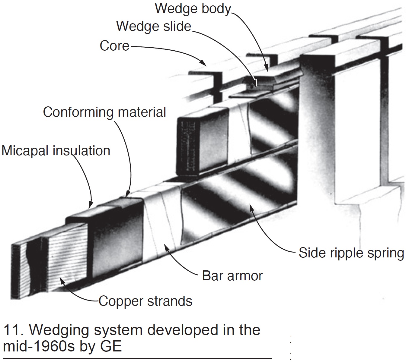
But most other manufacturers continued to rely on side packing and tight wedges. Finally, the industry added the radial pressure spring almost universally on large generators.
Slot bar vibration incidents continue to occur. But, in general, if the wedging system remains tight vertically, if clearance does not exist under the bottom bar, and if excessive side clearance is not permitted, problems are unlikely.
Endwinding support systems. In the early years, the endwinding EMF was so low that almost anything was going to be alright. The top and bottom bars in the endwinding, if tied together, form a rather strong mechanical structure. It remained primarily to support the bars (or coils) during installation.
The parameters relative to slot wedging and endwinding support have little in common. The endwinding EMF is lower but still substantial—roughly one-third to one-half that of the slot forces. Because the opportunities for supporting the bars in the endwinding are minimal, endwinding vibration has been more difficult to successfully address than slot vibration.
 Also, until recently there has not been available instrumentation to safely and accurately measure magnitudes of in-service endwinding vibration. Design engineers have not had tools to directly assess the success (or failure) of their new designs. Thus, engineers have had to rely on intuition and best judgment in producing new designs, and await accumulation of service experience to determine if the design change was successful.
However, as generators increased in size, the EMF became so great that endwinding vibration became ubiquitous. Starting about 1960, OEMs went into major development programs, spending millions of dollars developing designs that would hold the extremely high sudden short-circuit forces as well as the significant normal operation forces.
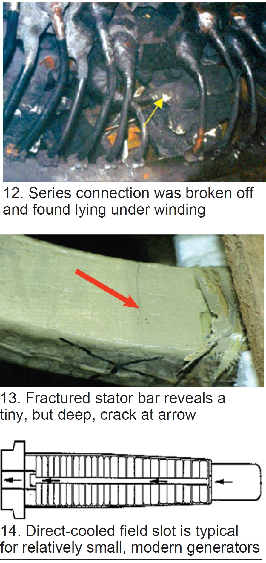
In spite of these huge OEM expenditures, endwinding support remains an ongoing problem. Parts become loose and wear holes in groundwall insulation. Connections become resonant and break off or fracture the bar (Fig 12).
Sudden short circuits can crack bars. It is doubtful that any design today can experience a worst-case short circuit without damage to the bars in the endwindings (Fig 13).
Stator endwinding concerns will remain into the future, particularly from local or general loosening of the systems allowing component wear to occur and resonances to develop. However, it can be expected that with the new capability to safely and accurately measure endwinding vibration, the designs will improve and reliability will increase.
Field windings
The mechanical forces on field windings are extremely high—resulting from up to 8000 g of centrifugal force acting radially at the tops of the slots. Metallic wedges can hold copper coils in the slots, and there are stable insulating materials that generally can function acceptably against these steady-state radial forces. It is the cycling duties resulting from start/stop and load changes that are the primary source of problems.
Winding copper is a main contributor to service issues. Copper has poor mechanical properties, even at room temperature. Yield strength is low, fatigue properties poor. At elevated temperature—above about 130C—these marginal properties begin to fall off. Unlike steel, copper only can be work-hardened; it cannot be hardened by quenching. With such poor mechanical properties, and high mechanical duties, engineers have been challenged to design support systems that successfully restrain copper coil dimensions and prevent their movement in position.
An indirectly cooled slot support design was shown earlier in Fig 9. In this design, heat losses must pass through insulation and forging iron to be removed by the flow of cooling gas. These indirect-cooled designs were used until direct cooling was required for higher generator outputs, starting around 1960. A typical direct-cooled slot is shown in Fig 14.
Electrical isolation in all field designs relies on “creepage” (voltage tracking over an insulated surface) and on “puncture” (voltage penetrating directly through an insulating material). Creepage isolation is used much more on the directly cooled windings, which makes them more vulnerable to contamination.
The radial blocking (red arrow) attempts to prevent both coil distortion and axial movement (Fig 15). Axial blocking (yellow arrow) primarily attempts to prevent coil distortion. But because the coils are not blocked continuously (to allow for cooling gas flow), and because of copper’s poor mechanical properties, distortion is common (Fig 16).
Because of the poor high-temperature properties of copper, significant over-temperature can result in fatal changes in coil dimensions. The result will be an immediate forced outage.
As windings lose position, the insulating materials tend to wear and crack. Grounds and shorted turns/coils result from damaged and contaminated insulation (Fig 17).
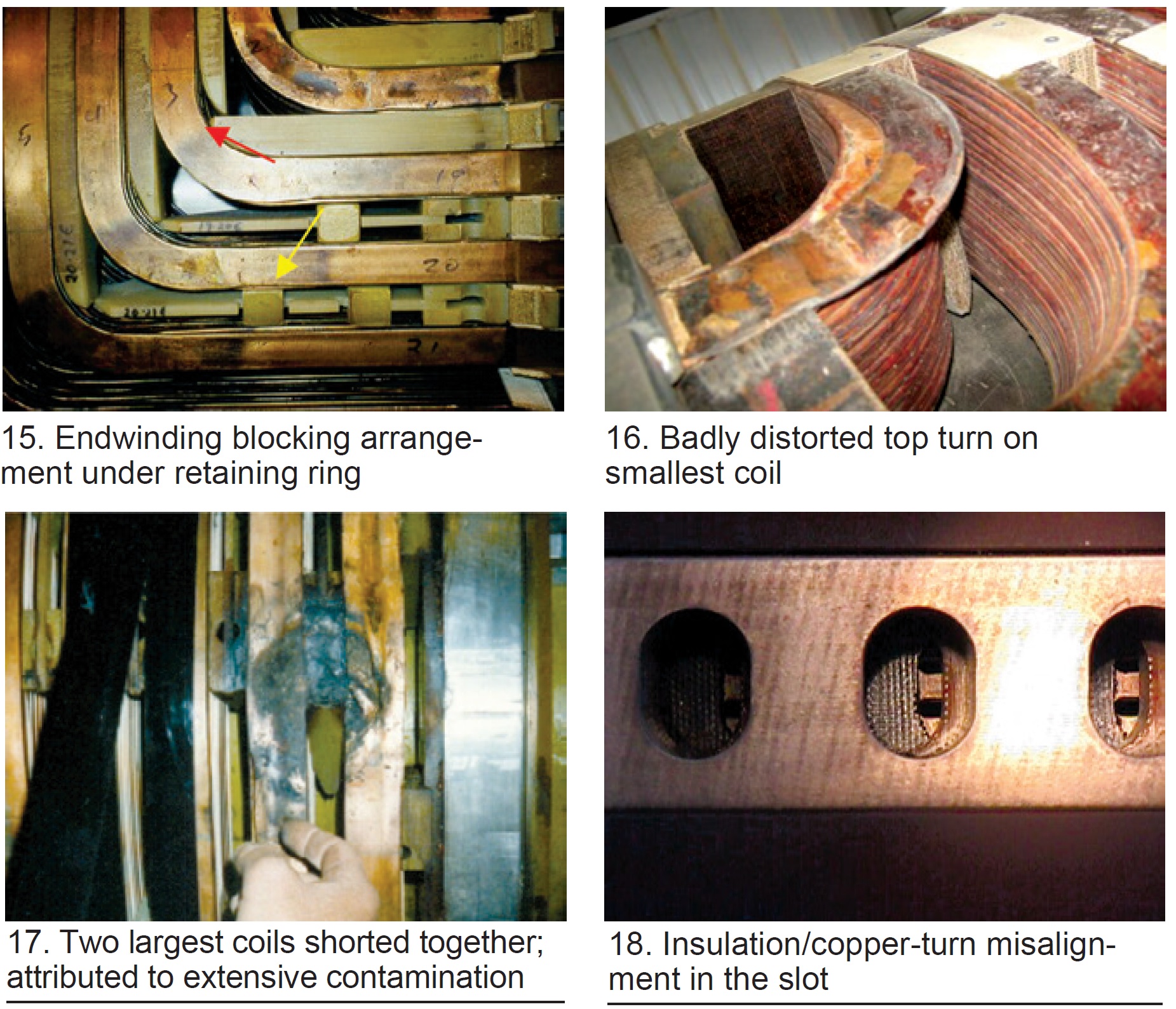
Further complicating reliable field operation is the need for uniform cooling of the coils in the rotor body. In Fig 18, the turn insulation and/or top creepage block have/has shifted axially out of correct location. This partial blockage of some slots and not others will result in bowing of the field (acting as a bimetallic strip). The resulting bow will cause a “thermal unbalance vector,” and as it grows over time, may force attempts to rebalance the field. If the conditions continue to deteriorate, eventually a field repair or rewind will become necessary.
Generators Table of Contents
Intro: Generators, a brief history
Part 1: Electrical insulation systems
Part 2: Winding support systems
Part 3: Generator cooling methods