The mechanical duties on rotor forgings are extremely demanding on the high-speed generators typically coupled to gas and steam turbines, and great effort has gone into development and optimum application of these forgings. Thus, a few words on this topic are in order here.
Rotor body forging
The main rotor body forgings reached a crisis point in the mid-1950s. During a factory high-speed balance, a body forging failed catastrophically in the OEM’s balance facility. Fortunately, the failure occurred during night shift and few workers were in the plant. But the two young test engineers operating the facility were both killed.
A few months later a field body forging failed in an operating power plant. Damage was considerable, but there were no casualties.
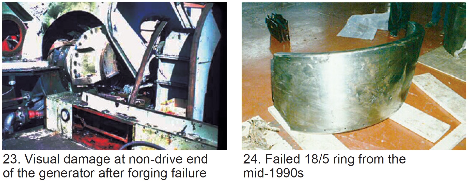
In 1956, a third rotor failed in an operating powerplant. (The writer would have been onsite at the time of failure had he been home to answer the phone.) This failure severely injured three or four persons and destroyed the turbine/generator (Fig 23).
The resulting investigations found that there were huge inclusions in the basic forgings—perhaps larger than 10 in. in diameter. These inclusions were inherent in the casting processes due to heavy contamination in the liquid metal. As the ingot cooled, the impurities percolated toward the ingot center and top.
Further contributing to forging vulnerability was that the materials had a Fracture Appearance Transition Temperature (FATT) of about 40C. This was totally unacceptable because it means that the material had poor ductility (behaved as a brittle material) below 40C, and was intolerant to fatigue stress cycles associated with start/stop duty.
Within a very short time the steel mills were able to produce forgings of much better quality and no further large-field forging failures occurred.
Retaining-ring forgings
Retaining-ring materials also went through a complex evolution. Originally rings were magnetic steel, but as size of generators increased a point was reached where rings of non-magnetic material would be highly beneficial. (This need is based on complicated electromagnetic design challenges related to excess end-of-core heating as load moved toward the leading-power-factor region.)
The most common of the non-magnetic rings was the 18/5 (18% manganese/5% chrome) material. It was found susceptible to stress corrosion cracking—that is, under high tensile load and in the presence of water, intergranular cracking occurred. This condition led to several ring failures (Fig 24). Needless to say, that stator winding damage was thorough.
Stress-corrosion damage progresses quickly. The ring in Fig 24 had been removed and given a full nondestructive test 18 months earlier and found trouble-free.
The problem with 18/5 material was recognized in the 1970s. Around about 1975, an OEM/steel-mill joint development program was initiated. From that effort the 18/18 (18% manganese-18% chrome) alloy was developed. The material, characterized by high and stable tensile strength, is highly specialized and can be produced only in relatively few facilities worldwide.
The 18/18 alloy is not nearly as vulnerable to the stress-corrosion phenomenon as the 18/5 alloy, and has been reliable in service since its introduction. It is now the industry standard material for this application.
Generators Table of Contents
Intro: Generators, a brief history
Part 1: Electrical insulation systems
Part 2: Winding support systems
Part 3: Generator cooling methods