Stator windings
Groundwall insulation. Before the turn into the 20th century, insulating materials were natural products: shellac, cotton, paper. The rudimentary stator-winding designs were at low voltage and low temperatures, and apparently functioned fairly well as long as duties were kept sufficiently low. With inevitable trends to larger generators, with higher voltages and higher thermal and mechanical duties, much better materials were required.
Somewhere around this time, mica flake was discovered to have remarkable electrical and thermal properties. But still with shellac, cotton, and other relatively primitive materials
incorporated in the systems, troubles continued. By the mid-teen years (1915) it was discovered that by using a vacuum-pressure cycle, mica/cotton tapes could be impregnated with a hot asphalt compound to obtain a major electrical duty improvement. Asphalt/mica systems served the industry well for 35 years.
About 1950, Westinghouse developed the first “hard” groundwall system—Thermalastic, a polyester resin system. This was a remarkable accomplishment, particularly in view of the relatively primitive resins available at that time.
Shortly thereafter, all OEMs developed hard groundwall systems, including the following: Micapal (a polyester-like epoxy), Micapal II (a true epoxy), Thermalastic-Epoxy (a true epoxy), and Micadur.
All these insulation systems rely on mica because of its remarkable partial-discharge (PD) resistance properties. (No man-made product begins to have the incredible PD resistance of mica. Bear in mind that PD is inevitable in the rectangular configurations of stator bars.)
But mica brings with it poor mechanical properties—brittle, non-extensible, no mechanical strength whatever in cross-grain tension. Thus, stator groundwall insulation systems remain with limited mechanical properties, and when subject to bending stress—short-circuit forces, for example—fracture about like glass.
In the 1990s, a global vacuum pressure system for the stator winding was introduced by Siemens. The GVPI system has major cost advantages and is used extensively on indirect cooled designs. Many of those stators have been produced and quality has been good. But if failure occurs, rewind is difficult.
Groundwall voltage stress levels. The stress on the groundwall has a dramatically important impact on electrically related problems associated with stator windings. The significance of this impact is better understood by realizing that duties associated with stress have been found to be in the range of a seventh- to 11th-power function of the stress level. For example, if the design stress is increased by 20%, the duty increases by 1.2 to the ninth power, or about 500%. Recognizing this attribute, design engineers have increased stress relatively slowly over the years.
By 1950, the stress level on the asphalt-insulation systems was about 45 volts/mil (vpm). With the advent of hard (polyester-type) systems, the stress level was increased to around 54 vpm. By the mid-1960s, improved (epoxy) systems were being used, and the stress levels increased to the low 60s. Today, stress levels exceeding 90 vpm are being used. The magnitude of 90/60 to the ninth power is about 3800%, an increase hard to contemplate. Expect electrical groundwall failures to become more common in the future.
Problems associated with groundwall voltage stress. The predominant problem associated with groundwall stress, PD, sometimes is incorrectly called “corona.” The stress gradient within the groundwall results in electrical breakdown in the tiny voids in the groundwall. These mini-arcs tend to eat through any insulation system without the PD resistance of mica.
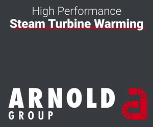
If the outside surface of the groundwall is not adequately grounded, there will be discharges of much higher energy. This, in turn, can result in surface PD. This condition, captured in Fig 1, appears very serious, but careful examination and scraping with a thumbnail would find little or no penetration into the mica groundwall.
Nevertheless, it cannot be ignored, especially in air-cooled generators, where ozone generation will be significant. Also, there is no assurance that penetration of the mica may not eventually begin.
Furthermore, the increased capacitive energy increases the duties on endwinding grading systems—for example, at the junction between end-arm grading and slot grounding paints (Fig 2).
The damage at this junction is often regarded as PD but is actually burning because of an inadequate interconnection to carry the capacitive current from the end-arm grading system.
 Where non-mica insulation has been used in endwindings, reliability sometimes has been seriously compromised. Example: Fig 3, where phase joints were insulated with non-mica potting compound and Nomex.
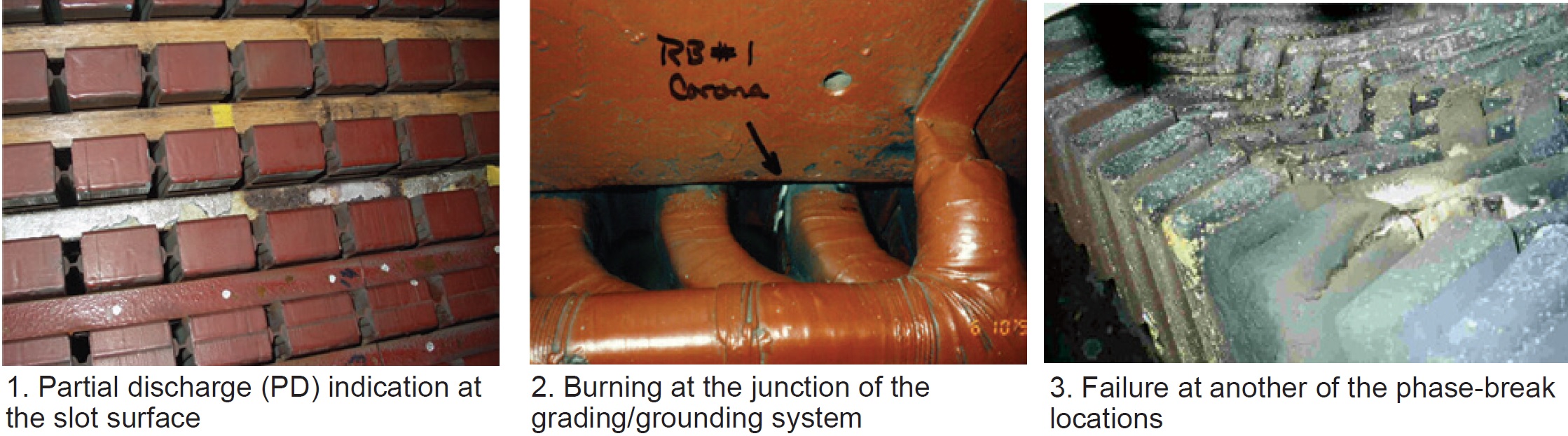
A large number of generators rely on physical spacing to hold the voltage stress. So long as the surfaces are clean, operation is satisfactory. But when surface contamination occurs, massive arcing can occur (Fig 4).
A final observation: Stator-winding electrical-arc damage normally accompanies stator-winding failure, but the actual root cause is usually mechanical—for example, vibration, fracture, foreign object, and contaminants. To this point in time, generator failures caused by purely electrical duties are uncommon.
Bare bar stranding. Because eddy-current losses would immediately melt a stator bar made of solid copper, a stranded design has always been required. On coil windings, no special transposition is needed—that is, the top and bottom bars of a coil automatically tend to cancel out the voltage difference between the top and bottom strands in the half-coils. (In this article, the term “bar” is used to define a half coil. For convenience the term “bar” is used almost exclusively.)
On bar windings where it is usual to solidly connect all strands at each end of the bar, this cancelation of radial flux difference in the slots does not occur. Very early (in 1912) a Swiss engineer, Louis Roebeled, invented an elegantly simple way to construct this transposition on bars.
His invention, the Roebel bar, was no great scientific discovery, but rather a remarkably simple way to accomplish a very difficult task—construct the transposition. It is so manufacturing friendly the Roebel transposition system is universally used by all OEMs, with the exception of those few who have manufactured smaller bar windings without consolidating the strands at the ends of the bars.
The standard Roebel transposition effectively compensates the radial flux-density gradient in the slot portion of the winding. But on larger generators of non-coil design, the radial flux gradient in the endwindings becomes sufficiently large to cause problems—a concern automatically eliminated in coil windings.
Several approaches have been used here. The simplest is that of a 540-deg Roebel rotation in the slot. (Note that Roebeled’s invention was single 360-deg rotation.) The somewhat complicated 540-deg rotation performs a correct compensation in the slot while inverting the strands at the two endwindings beyond the core.
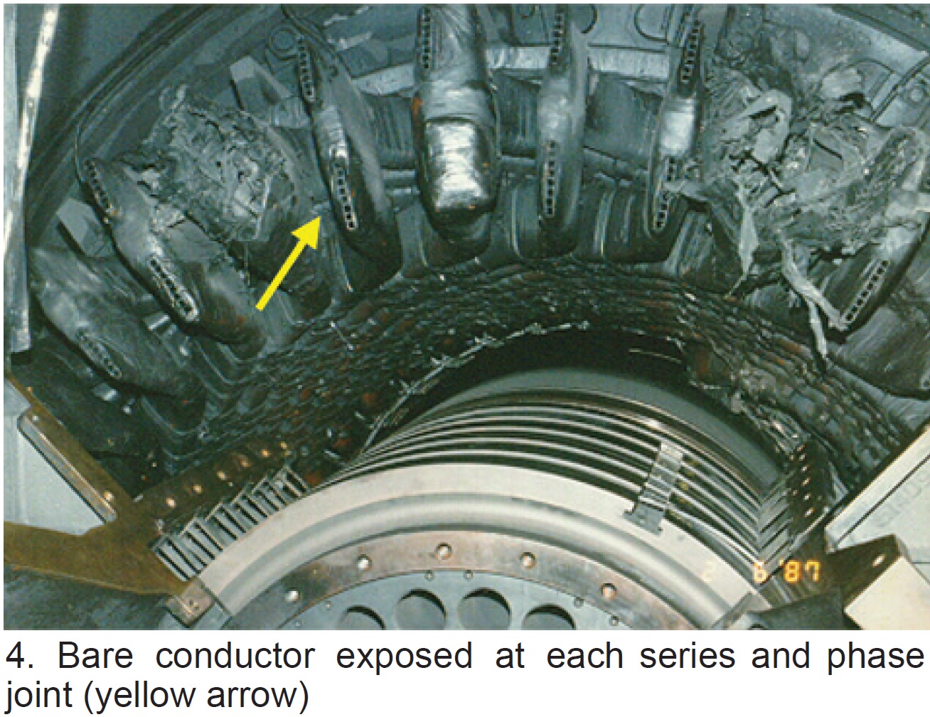
Another approach for endwinding radial-flux compensation has been to sub-group the bar strands into bundles of strands; bundles may range from as few as one strand to as many as 14, or more. These “bundles” are maintained throughout the entire phase belt. Bundle design greatly complicates the winding manufacturing process and has been accompanied by numerous service problems (Fig 5).
Strand insulation. A small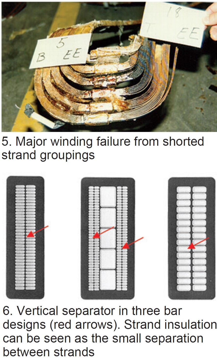 voltage exists between adjacent strands, probably always less than 1 volt, and the strands must be individually insulated. Originally, cotton would have been used, then glass, and now commonly Dacron-glass. The last material is thin, typically 1 to 3 mils/side.
A higher voltage exists between tiers of strands. Here a “vertical separator” is inserted between tiers. The stress may be as high as 15 volts and the thickness may be about 15 mils (Fig 6).
Voltage grounding and grading. If the outside surface of the groundwall is not tied electrically to ground, PD will exist between the bar surface and ground. Consequently, a semi-conducting (low resistance) paint is applied to the outside surface of the slot portion of the bar (and usually about 2 in. beyond the slot at each end). If properly applied, and of good quality, this paint will eliminate the PD by grounding the outside surface of the bar insulation to the slot iron.
More complicated is the necessity to “grade” the voltage of the grounding paint at each end of the slot (Fig 7).
The engineering principles here are complex, but the mechanics are relatively simple. Originally, asbestos tape was applied for a distance of perhaps 7 to 12 in. beyond the end of the slot grading paint, depending on winding voltage. In the 1960s, the industry went universally to silicon carbide—both to eliminate the hazard of asbestos, but because silicon carbide offers a more effective approach to grading.
Series/phase joint insulation. It is common to insulate these joints with mica tapes. Beginning about 1970, some designs used synthetic resins inside a non-metallic box. This is a marginally acceptable method at the phase connections because the voltages here are high.
Physical spacing also has been used by some OEMs. This design approach is safe—providing the creepage paths remain uncontaminated, and providing there is not a conductive plasma resulting from arcing of a failing electrical connection. In the event the insulating capacity is violated, a “ring of fire” can result (refer back to Fig 4).
Field windings
The duty differences between stator and field insulation systems could hardly be more different. On stator windings, the voltages are high but the mechanical stresses are low. On fields, the voltages are low, less than 700 Vdc, but the mechanical duties very high, in the order of thousands of psi.
Because of the low voltages, and the need for direct contact between cooling gas and winding copper, isolation using electrical creepage surfaces is common. So long as the insulation remains in place and does not become contaminated with conductive materials, the systems tend to perform well. But because the mechanical duties are high, problems can occur. They typically result from fracture, cut-through, and shifting of location of the insulation components. Result: Service problems relating to insulation failure are common on fields.
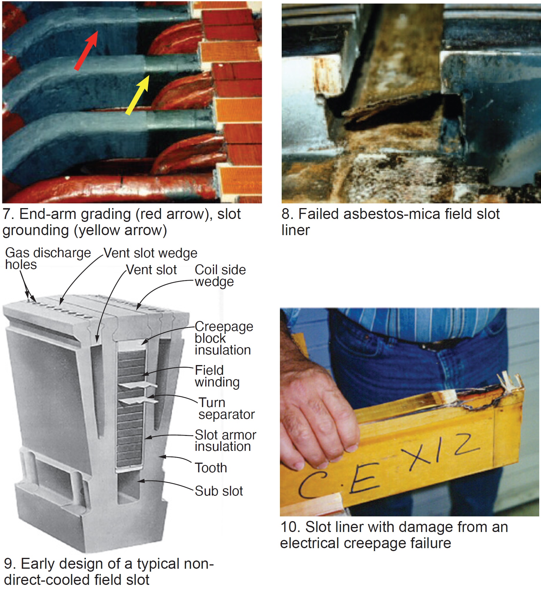
Slot liners (ground insulation). Until about 1960, ground insulation for coils consisted of enclosing the coil with cotton or asbestos cloth for mechanical stability and mica flake for insulating properties (Fig 8).
This composite structure served adequately because of the low-voltage stresses. More recently, Nomex, glass/epoxy fabric, and composites of glass/epoxy and Nomex have become popular. Generally, this ground insulation is in a U-shape, closed at the top by a creepage block (Fig 9). These ground insulation systems have been subject to failure primarily because of contamination, fracture, migration, and cut-through (Fig 10).
Turn insulation. The voltage between turns is low, typically 1 to 5 volts. Historically, mica tape was used, but since about 1960, thin glass/epoxy laminate has been in common use for turn insulation. So long as physical spacing is maintained, turn shorts are unlikely. However, the integrity of the space can be violated by fracture or migration of the material, or by conductive contaminants bridging the spacing. Failure of turn insulation is relatively common.
Endwinding insulation. Under the retaining rings, sheet laminate of heavy-weave asbestos cloth and mica was the historic insulation system. Again, around 1960 transition was made to a laminate structure of heavy glass cloth and epoxy resin. The laminate is degraded somewhat when the 300C retaining ring shrinks down onto the epoxy glass; however, the materials used are sufficiently thick and thermally stable that the electrical strength remains adequate for single use.
Insulating-block material is used to hold coil shape and to insulate the axial locations of the endwindings, as shown later in Fig 15.
Generators Table of Contents
Intro: Generators, a brief history
Part 1: Electrical insulation systems
Part 2: Winding support systems
Part 3: Generator cooling methods