Originally, generators were cooled by once-through open air flow. Contamination problems led to closed ventilation systems, with water-to-air heat exchangers to remove the thermal losses—the TEWAC cooling system (Totally Enclosed Water-to-Air Cooling). This type of system is still very popular for small generators.
But by the 1930s, ratings were reaching a size where the ability of cooling with air was limiting further increase in rating. Engineers recognized that use of hydrogen gas as the atmosphere had important advantages: low density, high specific heat, and the high thermal conductivity. In particular, windage losses were reduced to about one-fourteenth that of air. Also recognized: hydrogen gas is highly explosive, unless hydrogen purity (freedom from oxygen) was kept out of the range between about 4% to 94% oxygen, by volume.
A high-level development program produced the necessary hydrogen shaft seals and system controls to permit the first hydrogen-cooled generator to enter service in the USA in 1937. By coincidence, this was the year of the Hindenburg hydrogen-filled airship disaster. But there was no OSHA at that time, and hydrogen cooling came into common usage for large generators.
 Over the years there have been a few hydrogen accidents involving serious plant damage, and personnel injury and death. The nature of a hydrogen fire is such that damage can be dramatic—that is, hydrogen tends to detonate and produce a high-pressure wave that can blow the siding off an entire building and bend a steel door.
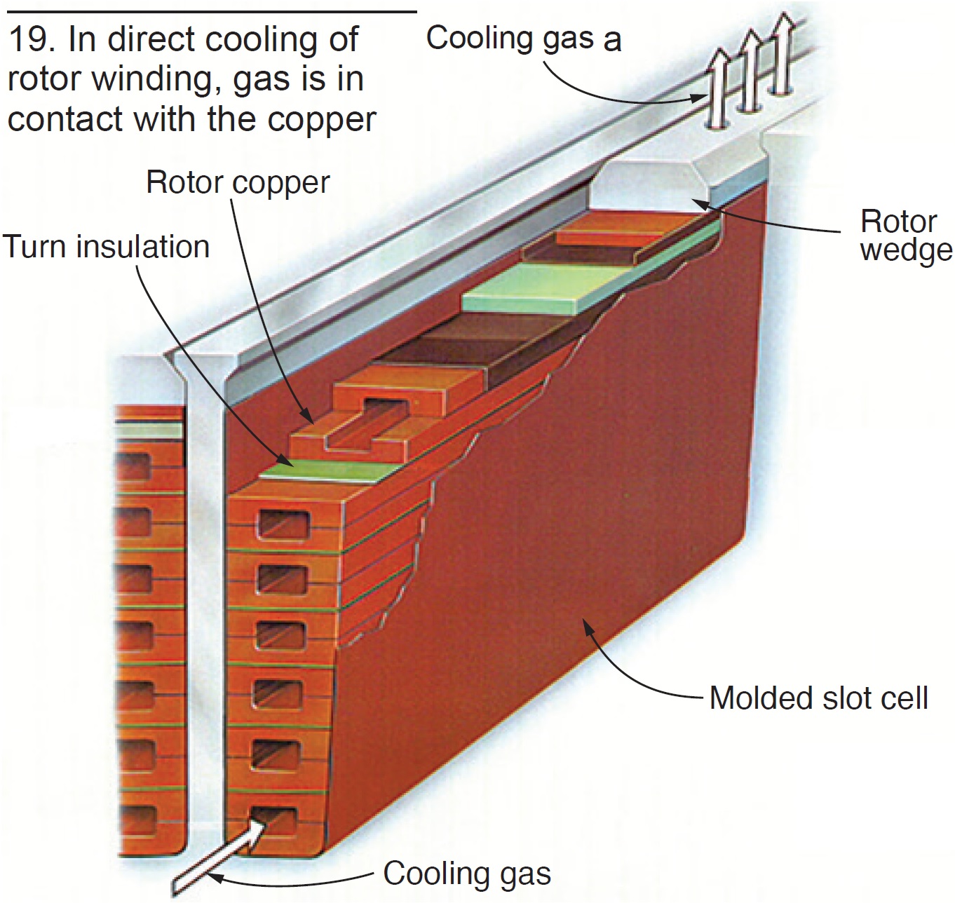
Size limitation came again at around 200 MW in the mid-1950s and manufacturers began development of “direct-cooling” methods—that is, the cooling media in direct contact with the copper electrical conductors of the stator and rotor.
In rotor-winding indirect cooling, gas flows in passages within the forging, thus cooling the forging. The cooled forging then cools the copper by conduction. With direct cooling, the gas is in direct contact with the copper (Fig 19).
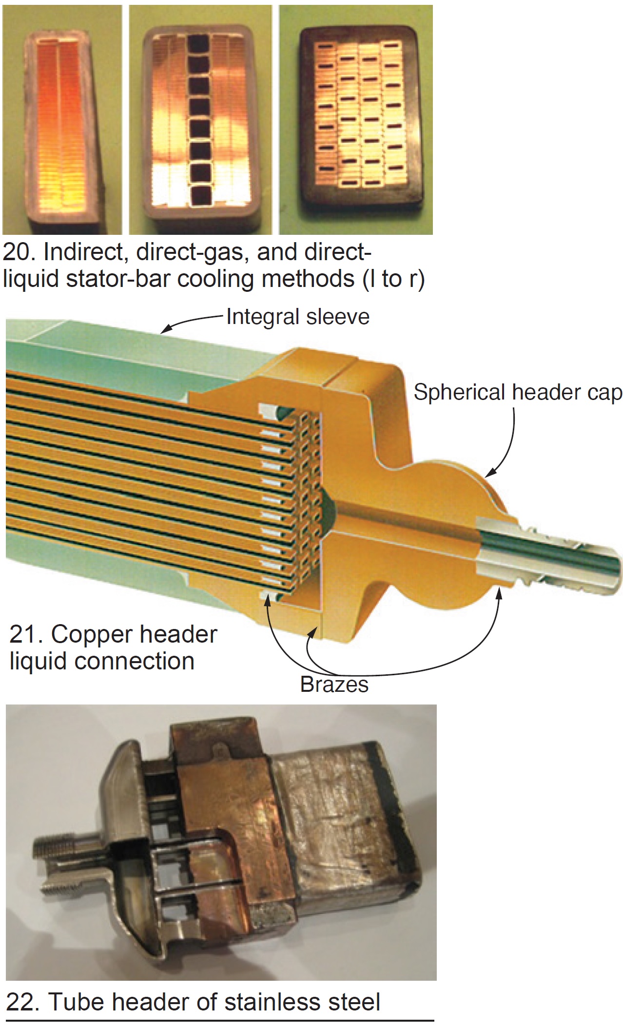 Stator windings until about 1960 were cooled indirectly (Fig 20 left). Two types of direct cooling were developed during the late 1950s and are in present usage, center and right bars in Fig 20.
With indirect cooling, all thermal losses must traverse the thickness of the ground insulation. Given that electrical insulation is an excellent thermal barrier, there was incentive to pursue direct cooling methods.
With direct gas cooling, only the strand and tube insulation must be traversed. These barriers are thin and offer little thermal resistance. The bar mechanical structure becomes rather complex in this type of cooling, but a very large number of direct-gas-cooled generators are in service and the design has generally has performed well.
With the common method of direct liquid cooling, the coolant is in direct contact with the heat-generating copper. Usually, a mix of hollow and solid strands is used with all strands brazed as a unit into a copper alloy strand header (Fig 21).
Less common is the use of stainless-steel tubes individually welded into a stainless header separate from the copper strand connection (Fig 22).
The direct-liquid-cooled designs have had OEM-specific service problems, but in general have performed well.
Generators Table of Contents
Intro: Generators, a brief history
Part 1: Electrical insulation systems
Part 2: Winding support systems
Part 3: Generator cooling methods