To some, here’s the distinction between reliability and resiliency: Reliability is avoiding a punch; Resiliency is recovering as quickly as possible from a punch. Aging assets, such as those with older turbine models, are likely going to take more punches than they avoid because the resources to avoid the punch are devoted to newer, more critical assets.
The third annual Legacy Turbine Users Group (LTUG), held in The Woodlands (Houston area), Texas, July 15-18, 2024, once again brought together under one roof owner/operators of Frame 5, 6B, and 7EA machines. With more users hesitant (for good reason) to propagate their machine experiences beyond trusted members of their own community, it’s becoming more and more difficult to gain much material benefit from the LTUG “after the fact”. So, if you are an end user of this equipment, consider attending the 2025 conference from June 16-19 in Minneapolis.
The value of attending extended beyond the hallways and breakout sessions of the hotel. LTUG 2024 hosted a full suite of shop tours, taking advantage of the conference’s proximity to Houston, the global epicenter of gas turbine repair. Users were treated to behind-the-scenes looks at the growing, impressive capabilities of Allied Power Group, Baker Hughes, Doosan Turbomachinery Services, and Sulzer Turbo Services.
Most slide decks for the 7EA and Frame 5 and just a few for 6B are posted at www.powerusers.org, where the three organizations reside online. More time is being allotted for roundtable discussions, less for formal user presentations. GE day slide decks are not posted.
Finally, vendor-led presentations are displacing user-driven ones. The real-time discussions are where the action is, and, like most things in life, you get out of them what you are willing to put into them.
However, there were several outstanding user presentations, one a post-mortem and root cause analysis (RCA) around a control system backup battery charger failure, a second describing an alternative to a diesel motor starter, and a third an RCA of a 7EA compressor failure. All three illustrate how these plants recovered quickly from the punch. A fourth covered the upgrade and overhaul of a 1970s-vintage peaking plant.
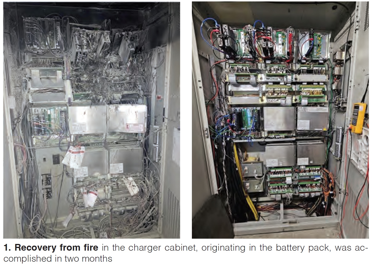
Fire in the cabinet!
Moral of this story is to assess old control system battery pack chargers, especially if you are migrating from Mark V to Mark VIe and you’ve retained the old chargers and I/O. Or just take some time to assess them period, including your fire suppression system.
A user with five dual fuel, standard combustion, 7EA machines commissioned in 1994 experienced a fire (dubbed an “unplanned combustion incident”) in the battery pack and charger cabinet (Fig 1) in February last year while the unit was in outage for a major inspection (MI). The plant had upgraded to the MKVIe MMV in 2016, but left the original battery charger in place. Batteries had been replaced in 2010. Photos reveal the extent of the smoke during the fire, and substantial damage to the cabinet.
Subsequent RCA revealed a flood of diagnostics and alarms from the subsystem, beginning in November the previous year, which would clear in milliseconds while the unit was off-line. This happened for “days and days when the unit was off-line.” It had “probably been years” since the unit was operated at its high voltage shutdown (HVSD) threshold of 150 VDC.
Lead theory of cause was that the charger was not charging the batteries and the DC voltage was cycling between low and high, which could lead to high heat conditions. An alternate theory, however, that could not be ruled out was that AC had gotten into the DC circuits via the failing battery charger or external source in the field.
Other RCA findings were that a planned maintenance (PM) strategy didn’t exist for the MKVIe MMV hardware and I/O, the only DC power to the MKVIe MMV was the batteries (no DC-to-AC converter, or DACA, also known as the transformer assembly, existed, which was “uncommon” according to the OEM and AP4 Group, who was assisting the plant)), and the wrong kind of fire extinguishers were stationed (not Class C CO2) in the area for this type of fire.
After evaluating options, the plant’s post-incident actions included correcting the gaps in PM and fire suppression, replacing original battery chargers, adding high/low DC voltage and other alarms, and establish voltage monitoring in PI and graphics in the MKVIe MMV.
AP4 agreed to rebuild the cabinet in two months while others, including the OEM, proposed schedules up to eight months. The slide deck includes photos of the cabinet rebuild and rewiring (during which the “sins of the past” were fixed), schedule, and ancillary tasks. Aside from a ground fault in the DC system and a damaged exciter card, which was inspected, cleaned, and returned to service, there had been no other incidents of note, nor any failed starts or trips.
An audience member noted that his plant had found oscillating charger voltages months before an “event” and that the chargers were “acting weird.” A second suggested that these components should be on a monthly NERC PM check. Best practice noted in the room: Make sure you have properly refurbished control cards on the shelf.
Hydraulic motor starter saves day
A facility with Frame 5 units in far north Plains country (i.e., really cold in winter) lost its aged diesel starting motor at the beginning of 2023. The unit had to be on-line by June 1, it was impossible to get parts for this Cummins machine. Multiple service vendors would not engage with the project because of “difficulty dealing with this particular starter package.” Thus, the owner/operator opted for a replacement skid consisting of a large electric motor plus a variable displacement piston pump (Fig 2).
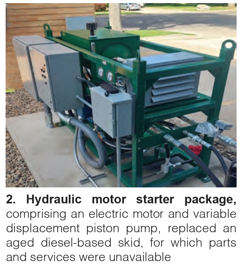
Focal points for the presentation were (1) the need to “weld in and weld out” to extract the diesel motor from inside the gas turbine housing in two pieces through the roof, without pulling the top off of the turbine, and (2) making sure new equipment in the gearbox room (designed for “someone four-foot tall”) was compatible with the components which were reused, such as the clutch.
Regarding the second, a repurposed carrier bearing was added inside the torque converter to the middle of the shaft. A stub shaft was also added to make a 2-in rotor on the motor side compatible with the 3 in rotor on the clutch side. Both affected the weight and structural design parameters. The new clutch “spins freely in one direction, engages in the other.”
Cold weather design points are particularly salient here. The facility required an insulated housing. Hoses had to be wrapped with heat tape. A separate start sequence had to be programmed into the controls, during which the pump motor is first run in neutral to warm the lube oil while limiting amp draw to maximize torque. When the pump hits full stroke, it is closed to light off the turbine.
The vendors involved with the project, ST Cotter Turbine Services and HPI Energy Services, reported that they rescued the facility “with a luxury yacht instead of a tug.” While they’ve completed hundreds of starters for FT4s, FT8s, and other machines, this was the first frame 5. Cummins is now said to be recommending the duo to customers in similar situations.
Other issues to consider:
- You need a specialist for the controls.
- Make sure the concrete pad for the skid can handle potentially higher vibration levels, which may also affect complying with sound level limits.
- Local codes for black start may require a soft start or variable frequency drive (VFD) set up.
- Motors up to 400 hp have been used, although this site required a 300-hp unit. Larger motors come with a larger footprint.
- Make sure you have enough fuel for multiple starts during commissioning.
The project schedule for the new starter was four months from finalizing paperwork to a fully commissioned skid. Actual installation took 7-10 days. At conference time, the unit successfully handled 21 starts. Plant is looking at obtaining additional hardware (larger valves, for one) so that two GTs can be started with the one unit.
Slide deck includes a more detailed description of the machine train and clutch assembly, an excellent series of project photos and a handy list of considerations for those contemplating a similar project.
Inlet bell mouth bolt ‘bolts’
A 1981-vintage, 7001E dual-fuel peaking unit at a Pacific Northwest coastal site, with almost 30,000 fired hours, close to 1500 manual starts, and 161 emergency trips, was down for a planned outage at the beginning of October 2023 when staff observed significant inlet guide vane (IGV) and compressor blade damage and missing split line bolt head. See the slides for photos showing details. Bolt piece was later recovered in the 5th stage extraction port of the compressor lower section.
The RCA concluded that the #3 right-side bolt on the air inlet fractured at the head radius and entered the compressor, causing domestic object damage to the blades, mostly the first four rows. Failure mechanism was that hydrogen-induced cracking caused long-term corrosion combined with elevated material hardness level.
Although 43 years of continuous exposure to the coastal environment and normal aging were likely responsible, overtorqueing during installation could possibly have played a role.
Compressor, turbine, and rotor were sent to APG’s shop in Texas, where the unit was destacked, inspected, repaired, rebucketed and rebladed, rebalanced, tested, and returned service by January 5.
That 70s show
Oil-fired frame 5 peaking units in the Midwest, commissioned in 1976, were overhauled and upgraded with project deliverables of 98% start reliability, 98% availability, and remote operation. The control system upgrade gives an even better idea of the vintage: from Mark II to Ovation.
Slides, in outline form, review scope items and division of responsibility, multi-contract approach, as-found plant description, and other project aspects. Among the challenges faced were lead times for the control system, inflation (budget was from 2019), and no-bids received from some service firms because of market demand.
Added scope items may be revealing to those with similar vintage units and upgrade ambitions: Inactive thrust bearing mod (TILs 533, 1019 and 1038), bearing and oil deflectors, starting motors, torque converters, exhaust casing, casing alignment and dowlings, stage 9 hook fit (TIL1304), and miscellaneous parts.
Troubleshooting refresher
Cutting across the 7EA and Frame 5 sessions was Dan Melsheimer, GT-DLM LLC, an industry veteran who delivered a refresher on troubleshooting. Those new to the industry should find the deck invaluable. What may seem to veterans like common sense items are, sadly, easily forgotten, especially when in the throes of trying to recover from an incident.
Learning the origin of the word “troubleshooting” alone is worth checking out the slides. If that doesn’t grab you, the photo of a fuel regulator trend graph (Fig 3) made with video data from three different iPhones should!

Melsheimer points out the technology gap with today’s technicians. Why? Most of today’s technicians were in high school when legacy machines were designed and installed. New technicians have trouble sorting through the notes on the original drawings.
While alarms are the key to tracking down issues, “you need your mind more than the alarms.” Causes of trips are often hidden in the drawings. On the other side of the equation, owners outsourcing maintenance lose control over the skills necessary.
Approaches to troubleshooting fall into three buckets:
- Shoot from the hip. Fix the first thing that comes to mind, which can be up to 95% effective if the people involved have experience.
- Shot gun – fix everything you can think of which might have gone wrong, even if it doesn’t identify the root cause and can induce other problems.
- Step by step – the preferred approach, of course, which involves lots of documentation and can be guided by forms and methods you can create. A sample is provided in the slide deck.
Being prepared for incidents before troubleshooting is critical. Have all drawings and documentation for the machine organized and easily accessible in one place. Set up files to record trends in the control and monitoring system. Make sure technicians are trained on the OEM drawing system, analog data collection, and devices you can use for analog data collection.
One user noted that their operators on shift are required to follow an RCA procedure sheet and email it to everyone regardless of shift. Another responded that if an incident can’t be fixed within four hours (which usually is the case), then a team-based step-by-step methodology is put into action.
Controls on main stage
Across the three parallel user group sessions, controls sucked up a good deal of the oxygen in the rooms, including the lead presentation in this summary. Here are others.
John Downing, AP4, made the rather startling observation in the 7EA track that life extension to 2065 is now being discussed. It takes little imagination to understand the impact of that on a facility’s control system. Digital control technology is arguably the fastest evolving area of plant components. Yet some plants have 30-40 year old thermocouples and pressure and temperature transmitters.
Downing suggested that plants create a book of all instrumentation and associated components, along with their calibration procedures. Dozens of parameters measured by these aged sensors are the basis for the automated instructions for the GT, such as raising and lowering speed and load. A dry low NOx combustor tuning sheet has 50+ data points. The reference temperature estimator at the inlet to the first stage nozzle is used to make all DLN operating changes. This is a calculation based on measured parameters.
In other words, there are critical control parameters and their associated measurements and information-only measurements. Downing recommends calibrating all instrumentation at least one a year and instruments involved in critical parameters twice a year. Also, there are “dozens of little gremlins addressed by the Technical Information Letters (TILs).
Emerson’s David Cicconi offered plenty of tips to the Frame 5 attendees on how to plan and manage a turbine controls upgrade. Slides run through scope definition which may include enhanced turbine control features; solving combustion system issues like unit turndown, trip system performance, flame detectors, and generator metering; and upgraded auxiliaries like fuel valves, generator controls, and speed measurement.
One point of emphasis was what to do with existing drawings, which are often inaccurate at best, non-existent at worst. When the OEM’s control system is replaced, other drawings are affected. You should consider a pre-outage audit to investigate discrepancies in drawings and other documentation, or at least add time to the schedule for field checks to drawings.
Cicconi noted a best practice to match existing wire numbers and signal names in the upgraded system using digital editing, i.e., colored lines, to clearly define scope and responsibility at contract stage, and to avoid replacing existing cables and devices and retain wiring loops.
Expect 12 months from purchase order to equipment shipment, and up to four weeks for site work.
Users responded during the Q&A with issues to be aware of, such as fire protection system integration into the upgraded controls and voltages compatibility with the new excitation system.
Young and Franklin presented on fuel gas electric valve upgrades for a Frame 5 unit. Y&F has been in the business over a century as a job shop to GE. In 2006, they began developing their own electric valve design to replace hydraulic models which leak and develop varnish. A typical Frame 5 has 10-12 of these valves, while a 7F could have close to 300.
Each valve comes with a digital motor controller (DMC), the “brains,” and is said to require minimal logic changes. Diagnostics from the DMC and USB connectivity ease troubleshooting and provide real time data to ascertain valve health. In response to a user question, the Y&F speaker noted that junction boxes could be mounted as far as 200 ft but with an arrangement where the junction box is “in the middle,” distance could be extended beyond 300 ft.
Users speak out on I&C. The following bullet points were gleaned from the 6B I&C roundtable discussion session:
- There is no Mark VII control platform in the OEM’s planning cycle
- No one responded when asked by the facilitator whether they’ve had negative experiences with the VIe platform.
- Some firms will rebuild valves otherwise thought to be not serviceable – including gas control, inlet guide vane, and safety relief.
- “Everyone” has issues with servo valves – keeping varnish quantities low is critical. One tip: let oil circulate for a couple of days after an outage to flush out debris. They are difficult to service, so are generally just replaced.
- Compressor bleed valve solenoids are a “perennial problem” because they pull in 700F air if you have a leak.
- Needle valve on the fill/drain torque converter is often incorrectly set.
- If you have a diode failure in the brushless excitation system, replace it as soon as possible. Make sure exciter diode replacements weigh the same as the old ones, shave off some copper if necessary, or make sure they come from the same supply source. The OEM gets them from different suppliers.
Maintenance strategies: peakers
Being old is one thing. Being an old peaking unit requires a different type of maintenance strategy. Attendees were treated to a roundtable discussion on this topic for Frame 5. Keep in mind that these users are commenting from different perspectives – island locations, unmanned units, remote locations, etc.– and different machine vintages.
Users reported different schedules for starting the units as a checkout. One said they started every 4-6 weeks, two users said once a month unless the unit was called to run, a third said startup to crank speed once a month, and to breaker speed every quarter (minimum, no load). Operator “rounds” are conducted every week, said multiple attendees, in one case by rotating technicians.
Ratcheting got good airtime. Schedules vary from once a day for eight hours to once a day for fifteen seconds. A user with 1970s-vintage units said they experience “no problem with the turbines themselves.” User, mentioning their Ovation system, said their units ratchet once a day, and an alarm sounds it if doesn’t. Another said that operators trend and verify pressures and timing, and take the unit to maximum ratchet pressure during the weekly rounds.
Others noted that the oil system stays on 24/7 to be ready for startup, lots of issues crop up with starting systems, the turbine compartment is kept at 95F to prevent condensation-driven corrosion of blades (which did occur over several years), and peakers are running more in winter than summer. Upgrades mentioned include switching to modern relays and adding instrumentation to the starting motor.
A user asked if anyone had removed the liquid fuel atomizing air blower for duel-fuel units. They tend to fail, this user noted, questioning what they contribute, and are costly to maintain. Others cautioned that the unit could “smoke” without the atomizer, or lead to coking on the crossfire tubes. Lots of condensation passes the atomizer during startups, warned another.
Inlet guide vanes are borescoped (BS) annually by a service firm, said a user, to check for bushing clearances (among other things) and eddy-current-inspect row 1 (looking for oil leaks). They have to pull four nozzles because the BS plugs are “useless.”
Other experiences include a fire in an unmanned unit when hot gas from a small leak in the exhaust contacted leaking oil dripping on debris left from some inappropriate contractor work involving sound cladding and grout. Staff didn’t know the unit was on fire until the fire department called. Users noted that raccoons often nest in remote units and pigeons get in the mufflers of the diesel starters.
Finally, a user conceded that the maintenance strategy is driven by “what bit them last time,” which led to a discussion of corrosion issues with lube-oil coolers (fins breaking off, among them), and replacing shell and tube heat exchangers.
Buckets and casings
Here are the more salient points emanating from the 6B turbine discussion:
- Dozens of users will be lining up for new casings
- Non-OEM casings are not yet available; there’s not enough demand
- One user reported their casings have been patched up four or five times already
- Is there a good abradable casing coating that can last a major operating cycle? No, said one user. Some don’t last a year. You have to remove the coating every repair cycle. One user applied titanium paste to casing cracks; they’ve lasted a year and a half so far.
- Take care of the rotor and the casing at the same time; it’s more expensive to buy them separately.
- 1st stage bucket rock was solved by coating the area on either side of the cooling passage. One user was “in favor” of thermal barrier coating on the 1st stage nozzles, but not for buckets, suggesting they be discarded because the cost of refurbishment is so high.
- General rule of thumb: When you run parts longer, you repair more after.
- Make sure water or air is run through cooling holes of new or repaired buckets and send someone to the repair shop to make sure work is done correctly.
- One user favors x-ray inspection of 2nd and 3rd stage buckets.
- User reported that “angel tip wings” on 3rd stage shroud block wore out after 30K hours.
Vendor presentations
Extending service life of 7EA components
MD&A
Jose Quinones
Every option for replacing 7EA components poses risk, whether new or repaired from the OEM, repaired by a non-OEM service provider, or obtained from another user. Consider this: Sometimes, 50% of repaired components are scrapped because they were damaged during repair! MD&A manufactures parts with improved alloys that can significantly enhance operating life and going-forward economics. Numerous examples of damage mechanisms, testing procedures, repair techniques, and advanced alloys are included for 2nd and 3rd stage blades and 1st stage nozzles (Fig 4).
Rotor life extension management – User case trends and recommendations
GE Vernova
Taylor Williams
Some 6B machines have been “out there” for 45 years. Users were cautioned that the 200,000 factored fired hours or 5000 factored starts limits (signaling end of rotor life) are “not conservative values.” To drive home the risk of continued operation, presenter cautioned that the “blast zone” for throwing a wheel is two miles because the casing is not strong enough to contain wheel liberation. Presenter reviewed TILs1049, 1382, 1576, GER3620, and PSSB20240307A and recent updates.
Compressor stator vane looseness
CTTS
Rich Armstrong
There have been multiple crashes across all legacy (and current) turbine models with square-based stator vanes. Message here is that the OEM’s “big foot” solution for loose stator vanes “doesn’t work,” and that an optional solution, applied to four units (at conference time) this year alone (and dozens of units over two decades), is available. Slides review evidence of shim and vane damage and fretting, tip rock, measuring vane looseness, explanation of the phenomenon, and details of the vane-pinning alternative.
Air filtration and extreme weather
Donaldson Filtration Solutions
Bob Reinhardt
Bulleted options are listed for these extreme weather events: snow and ice, wildfire smoke, extreme heat, and high humidity and coastal locations, along with preventive maintenance tasks.
EOP-012-2 extreme cold weather preparation for GOs and GOPs
Entrust Solutions Group
Rachel Williams
Slides cover basics you’ll want to know about (1) new requirements issued by the North American Electric Reliability Council (NERC) in EOP-012-2 (update from EOP-012-1), cold weather preparation standard, and (2) being able to demonstrate that you can operate at the extreme cold weather temperature (ECWT) conditions. Now you have to calculate your unit’s ECWT, and document critical components, specific freeze protection measures, and cold weather constraints, as well as develop and implement a corrective action plan (CAP) to address deficiencies. If you need an incentive, the penalties are as high as $1-million per day per violation.
Impacts of increased cycling on critical components
EthosEnergy
Ravi Annigeri
Greater cycling significantly affects turbine operation, performance, and life of components. Ethos has solutions to address turbine bucket rocking, a primary impact of cycling. Its EcoMax Combustion Tuning system can optimize performance during starts and load cycling. Digital Twin model, fined tuned with field reports and data, serves as a basis to analyze rotor components and address known issues and failure modes, improve stress/life, and maintain interchangeability and compatibility.
Torque converters in starting packages: Long term wear and failure modes
Powerflow Engineering Inc
John Baciak
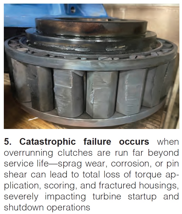
Slides outlines fundamentals of torque converter (TC) design and operation and reviews primary damage and failure modes such as piston wear, external oil leaks, worm/gear shaft failures points, anti-friction bearing failures, thrust and journal bearing wear, overrunning clutch wear and failure, cavitation erosion, and others (Fig 5). Among best practices noted: If you have multiple units, have no spare TC, and don’t know the condition of the TCs you have, overhaul one to determine the likely condition of the others.
Technology and applications of turbine coatings
Liburdi Turbine Services
Doug Nagy
Extensive primer covers cold and hot-side turbine components and the coatings used to protect their surfaces, coating deposition and application processes, selection criteria, types of coatings for various locations, compositions and microstructures, as well as advanced technologies, including nano-structured materials, suspension plasma sprays, cold sprays, low conductivity thermal barrier coatings (TBC), and degradation mechanisms.
Decarbonizing the Gas Turbine Fleet: Update of Current Combustion Offerings
PSM Thomassen Energy
Mark Kooister
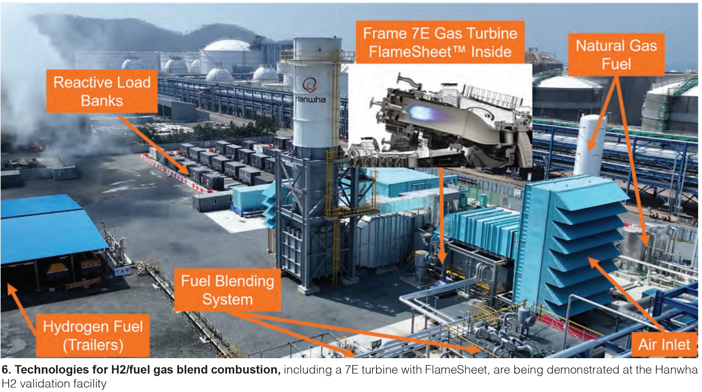
Slides review PSM Thomassen’s global footprint in services and units, it’s strategic plan in providing technology and options for decarbonization, 6B product line, Frame 5 upgrades, waste gas and high-hydrogen combustion technologies (Fig 6), FlameSheet retrofit platform, commercial adoption of H2 retrofits, and scaling challenges with a Frame 5 FlameSheet, among other topics. A 100% H2-fired Frame 5 demo is due to start operating in 2026.