


Replacing GT insulation promotes safety, speeds maintenance
Insulation can wear out faster than you think, particularly that installed on gas turbines with issues dictating frequent removal of their upper casings. If your unit was purchased during the bubble of 1999 to 2004 and still has the original turbine insulation, consider conducting a thermal survey to evaluate its effectiveness.
Benefits to replacement typically include less heat loss, a reduction in insulation removal/replacement time during outages, greater flexibility in maintenance scheduling, and longer lifetimes for in-package equipment—especially heat-sensitive motors, wiring, and instrumentation sometimes associated with unit trips.
Last spring, the editors were invited to a 2 × 1 501F-powered combined-cycle facility to see first-hand what’s involved in a re-insulation project. A follow-up conference call with plant personnel two weeks ago confirmed the near-term benefits expected. Obviously, questions regarding insulation durability will go unanswered for several years.
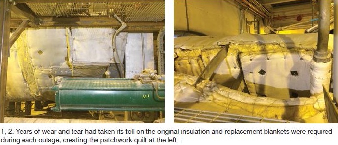
The project objective was to replace insulation on one GT and use the second machine with the original insulation for comparison purposes. Based on results thus far, plans are to re-insulate the second unit during the first planned outage after budget approval. Plant personnel said the original insulation, installed in 2000, had deteriorated to the point where about 15% of it had to be replaced during each outage, at significant expense (Fig 1).
Also mentioned was blankets normally last three to five off/on cycles and that, after an outage, it can be difficult to reinstall them properly, especially where they overlap. This is particularly true, it was said, when the blankets are held in place by pins welded to the casing. Pins occasionally are viewed as a field-service safety issue and if removed during maintenance and not replaced there’s little chance of getting blankets tight (Fig 2).
Several other concerns of plant personnel regarding marginally designed and ageing insulation systems include these:
- Insufficient protection for thermocouples, borescope inspection ports, and instrumentation.
- Maintenance activities that require walking on insulation can move blankets out of position and/or release fibers—a possible health issue.
- Sagging of insulation can cause uneven thermal expansion of the casing.
- Higher temperatures in the enclosure and operator safety concerns.
- Higher noise levels.
Looking to avoid problems sometimes associated with insulation offered on a low-first-cost basis, plant management selected a system supplied by Arnold Group based on life-cycle cost. To be fair, personnel acknowledged that the original insulation was subjected to very harsh conditions during the plant’s first 10 years of operation.
Project scope included re-insulation of the compressor, combustion, turbine, and exhaust-cylinder sections up to the first flanges, as well as of the exhaust-bearing tunnel.
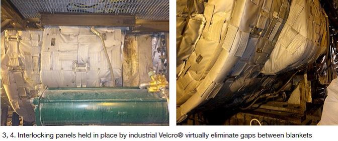
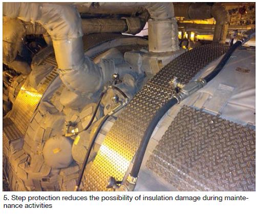
What plant personnel said they liked about the Arnold product was its varying thickness to maintain a consistent temperature across the entire machine and its interlocking panels, held in place by industrial Velcro®, which eliminated gaps between blankets (Figs 3, 4). In addition, the retention hardware attached to the turbine casing enables insulation attachment by studs and nuts, promoting tight fit up without the safety concerns associated with pins. Step protection supports safe maintenance practices and protects blankets from wear and tear (Fig 5).
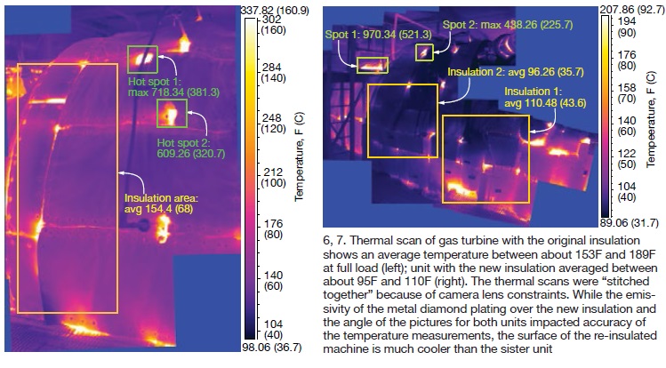
The plant benefited financially from the cooler package and lower insulation surface temperature provided by the new insulation (Figs 6, 7). To illustrate: (1) Change out of witches’ hat strainers was accomplished in less than half the time it took with the old insulation. (2) The pulling of gas lines on baskets at the bottom of the unit was done after an overnight cool-down—much faster than previously. Plus staff was happy not to suffer “hot foot” from walking on the top of the turbine. Regarding thermal performance, engineers said the heat-rate benefits would be difficult to calculate given the number of variables requiring consideration, and likely would be small in any event.
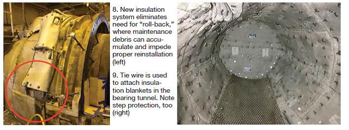
The new single-layer insulation system is relatively complex, requiring about 450 blankets for a 501FD2. The maintenance manager said he believed a technical advisor (TA) might be required if a given task required removal of a large number of blankets—just to save time. However, he added, only about one-third of the insulation must be removed to lift the upper casing. This would eliminate the “peel-back” issue that was an annoyance with the original insulation. That’s where waste material from maintenance activities would collect between the insulation and casing, impeding a proper replacement (Fig 8).
A benefit cited for having hundreds of individual blankets—all numbered to simplify ordering of replacement pads—is easy access to critical instrumentation, borescope holes, etc, for inspection, maintenance, or replacement without impacting dispatch availability, which had been a problem in the past.
The new insulation system for this 501FD2 took 21 days to install—in large part because of the retention brackets and studs requiring attachment to the turbine case. Payback for this effort is faster removal and replacement of insulation during outages when time is critical. The maintenance manager said preparations for a cover lift today should not take more than a shift.
Insulation in the bearing tunnel also was replaced as part of this project. In Fig 9, note that tie wire (not pins) fastened to support brackets is used to attach insulation blankets on internal surfaces rather than the Velcro used on external surfaces. Also, wear-resistant aluminum plating protects the bottom of the tunnel.
Insulation replacemen t: Key steps. The success of any engineering project depends on rigorous planning. Pierre Ansmann, a member of Arnold’s management team, told the editors at the company’s booth during the vendor fair for CTOTF’s 2014 Fall Turbine Users Conference that a good first step for an insulation replacement project is a photo session with the candidate turbine. The laser scan allows the company’s design and manufacturing personnel to adjust existing shop patterns for a particular engine model to the unit being re-insulated. Bear in mind that in-package piping and equipment arrangements vary.
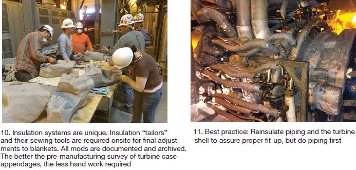
Adjustments to the manufactured blankets may be required in the field to accommodate such things as flange sizes, thermocouples, borescope inspection ports, etc. This work is done by experienced technicians—think of them as tailors—equipped with the proper sewing hardware (Fig 10). The most economic scheduling for insulation replacement is about 20 single-shift weekdays with one TA and six local insulators. Calendar time can be reduced, of course, by working weekends, increasing the number of TAs, and running double shifts.
Work begins when the turbine is cold and proper scaffolding is installed, if necessary. Insulation is removed by a local contractor, typically in a day and a half, and plant I&E technicians remove all instrumentation. About another two days is required to cut off all pins installed to accommodate the original insulation system, grind the pin stubs smooth with the casing, and brush/vacuum the unit and package clean. Respiratory protection is highly recommended during this work. It’s also a good idea to have a health and safety engineer to measure the concentration of dust in the package to assure safe working conditions.
Installing the retention brackets and studs required to position and attach the new insulation is the next step. If the casing is forged steel, these components can be welded to the casing; if cast, drilling and tapping are required. Both procedures are done in accordance with the OEM’s procedures. At this point, may be a good idea to laser scan the unit again to pin-point the location of all attachments, just in case.
Final steps: Install the new insulation system, have I&E techs replace instrumentation removed previously, and remove any temporary scaffolding. CCJ