


Coordinate generator, engine overhauls, upgrades
By Paul Heikkinen and Phil Karwowski, TurboCare Group (now EthosEnergyGroup)
(click to enlarge photos)
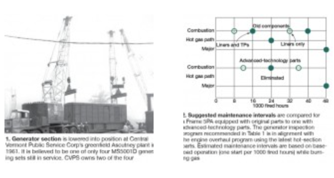
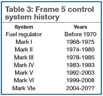
The Frame 5 gas turbine originally was manufactured by General Electric Co and subsequently produced by GE and its licensees—including Bharat Heavy Electricals Ltd, John Brown Engineering Gas Turbines Ltd, Hitachi Ltd, Alstom Power, and Nuovo Pignone SpA (later acquired by GE). Introductory Frame 5s were rated at 10,750 kW (Fig 1), with current versions up to 26,800 kW in single-shaft configuration and 31,100 kW in the twin spool arrangement (see previous article for gas turbine details).
Generators from many manufacturers have been coupled to the Frame 5. In addition to the engine suppliers listed above, one may also find generators manufactured by Brush Electrical Machines Ltd, Meidensha Corp, AEG-Kanis Turbinenfabrik GmbH (later acquired by Siemens AG), and others. The majority of these generators are air-cooled, employing either OAC (open air cooled) or TEWAC (totally enclosed water to air cooled) variations; however, some applications may use hydrogen cooling. Typical voltage is 13.8 kV at 60 Hz and 11 kV at 50 Hz, although it is not uncommon to find voltages from 4.16 through 15 kV.
Inspection, testing
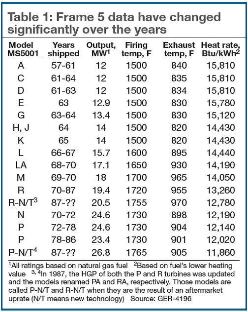
Hot-section component improvements have allowed users to extend their gas-turbine inspection intervals well beyond those that had been recommended by the OEM up until only a few years ago. Fig 2 compares yesterday’s intervals with today’s for the Frame 5PA.
 Important to note is that insurance-industry experts have advised against conducting ac high-potential testing as part of regular inspection and maintenance activities because these tests can be destructive. Industry trends suggest that a controlled dc over-voltage test—such as stepped-voltage testing and ramped-voltage testing—are more appropriate for maintenance assessments.The inspection schedule for advanced technology parts fits well with what generator experts recommend for their equipment, making it both logical and good operating sense to align generator and GT maintenance activities. For backup units that run infrequently, owner/operators might consider inspecting their generators at three-year intervals aligned with the scope recommended in Table 1 for “rotor-in” testing.
Issues identified at lower voltages can be corrected before proceeding to rated voltage multiplied by a factor for conversion to ac. However, ac high-potential testing is appropriate for proof-testing a generator that has been rewound either in the factory or the field.
During a combustion or a hot-gas-path (HGP) inspection, when the generator rotor remains in the stator, it is always good practice to measure and record stator and rotor electrical data—such as insulation resistance (IR), winding resistance, and Polarization Index (PI). Also, check to insure that resistance temperature detectors (RTDs) and thermocouples are functioning.
Historical records should be established and trended to provide a foundation for decision-making. For example, if the IR value of one phase is lower than the other two phases, and it does not change over time, then the likelihood of a developing maintenance issue is reduced.
Electric generators naturally operate best when clean and dry, so pay close attention during inspections to enclosure sealing, oil-seal clearances, resistance-heater operation, and paths of moisture ingress. These small steps can help extend the operating life of the insulation systems. Test heaters and their attendant control systems during planned maintenance.
Stator cleaning can be accomplished with CO2 blasting, solvent cleaning, hand cleaning, or a combination of these methods. Rotor cleaning is best done in a qualified shop. In all cases, be certain to test for lead paint and asbestos before initiating any cleaning or repair activities. If the generator tests positive for hazardous materials, remediation should be performed only by trained abatement specialists.
When planning a GT major inspection, it’s a good idea to consider cleaning and pressure-testing the generator air cooler. Factor the cooling-water source into your thinking.
CLICK HERE TO READ “REBUILDING A CLASSIC IN 15 STEPS”
Generally, all stator maintenance and repair work can be accomplished in the field— from testing and cleaning, through stator recore and full rewinds. A complete stator re-wedge can usually be done in a few days, which is well within the outage windows allotted for the gas turbine.
If insulation distress is apparent, keep in mind that with today’s reverse engineering capabilities and fast manufacturing cycles, it is possible to do a complete in-place stator rewind in about 45 days—that is, from initial identification of a winding issue, to stripping the unit, to final high-pot testing and turnover for mechanical assembly. These schedules are supported by pre-defined insulated copper, resin-rich mica tape insulation systems, and flexible-coil former technology.
For loose cores, tightening is often performed in the field without adverse effects. Pre-tightening and post tightening El CID testing can verify core integrity during this process.
If stator-iron damage is identified, repair or replacement of the core depends on the extent of damage. In the past, core replacement was almost always performed with the stator positioned vertically. However, in some plants, the cost of stator removal for re-core is prohibitive. Horizontal stacking methods have been used frequently to repair cores in-situ, saving the cost of a heavy lift and also reducing the critical-path schedule.
 Maximizing productivity
A typical Frame 5 generator has an expected lifetime of 30 to 40 years; some machines last longer, others fail sooner. Timely upgrades can boost productivity and help your unit achieve a long and productive life. Enhancements are available for minimizing the chances of an expensive failure, reducing the cost of maintenance, boosting output, etc. It basically comes down to economics: Is the payback worth the cost of the upgrade and the peace of mind that comes with it?
What follows are some upgrades and maintenance best practices for you to consider:
Stator rewind. Your vintage generator may still have its original asphalt mica folium stator windings, complete with hardwood wedges, string-tied end windings, and circuit ring cabling (Fig 3). With regard to return-on-investment, a stator rewind, whereby the windings are wound back to zero-hour, is perhaps the most beneficial upgrade of all. Another benefit: You generally can expect a 10% to 15% improvement in kilowatt-hour production with the switch from Class B to Class F insulation materials.
Rotor rewind. The original rotor winding insulation system in your classic Frame 5 probably consists of large flake mica and Class B-rated binders. Anticipate that your original end-winding blocking contains asbestos. Again, abatement, performed by a hazardous material specialist is important.
The original main field winding may or may not be suitable for reuse. Determining factors include tensile strength, yield strength, amount of physical distortion, etc. A complete rotor rewind, using an all-new Class F-rated insulation system would provide benefit in extended service life and uprate potential (Fig 4).
 Retaining-ring replacement. Retaining rings arguably are the most critically stressed components within a generator. The stresses in the rings (especially at the fit areas) alternate between compressive load at standstill, and tensile load at speed. Your vintage generator may still have its original rings.
Replacement rings are forged from 18Cr18Mn alloy and can be of the ventilated or non-ventilated designs (Fig 5). This modern material is mechanically superior and much more corrosion-resistant than steels used in early Frame 5s. The 18-18 material typically is in stock, so if an issue arises suddenly, new rings can be manufactured without affecting the rotor rewind and/or recondition critical path.
Retaining-ring insulation. Current practice is to manufacture new retaining- ring insulation from a single piece of spun-wound epoxy-glass. The multiple layers of insulation and epoxy used previously are less forgiving to process variations. During rewind operations, modern insulation can be manufactured to give a precise fit, preventing looseness and gaps which can allow the end arms to expand radially outward (Fig 6).
Collector-ring replacement. Collector rings can be remanufactured and replaced during rotor rewinds and/or reconditioning activities (Fig 7). This area often is overlooked. When replacing collector rings, new and improved insulation is added between the collector hub and the rings. The axial and radial lead insulation systems often are replaced during a rotor rewind. A word of caution after replacing the collector rings on the rotor: Make sure the brush rigging is realigned concentrically with the restored diameters to prevent rubs.
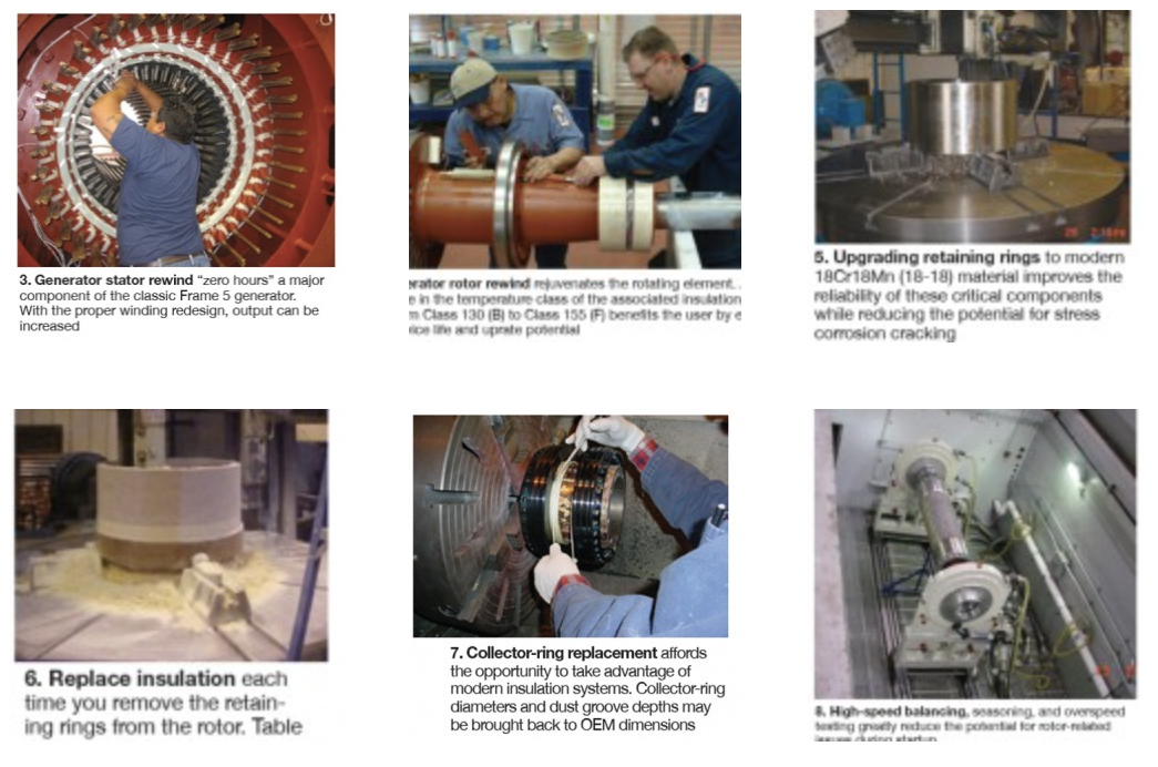 Various examinations are conducted at standstill, as well as at operating speed and temperature, to insure that shorts and grounds do not develop. More expeditious and less expensive corrections are possible, since they are found before the generator is reassembled. The time requirement for field balancing is often eliminated or reduced to only a touch-up balance move. TIRs recorded before and after balancing insure mechanical fixity of all rotor components.High-speed balancing, seasoning, overspeed testing. Although rotors can be rewound in the field, the inability to high-speed balance and conduct sophisticated electrical tests after the work is done increases the risk of startup issues (Fig 8). For example, during high-speed balancing, it is possible to test for shorted turns using the RSO (recurrent surge oscillograph) process, flux probe testing, and/or ac impedance testing. The rotor also can be tested for a running ground by performing an at-speed IR test.
Overspeed confirmation (at either 110% or 120% of rated speed) insures the mechanical integrity of all components. After fully reconditioning a rotor, coupling faces and diameters should be restored to design conditions.
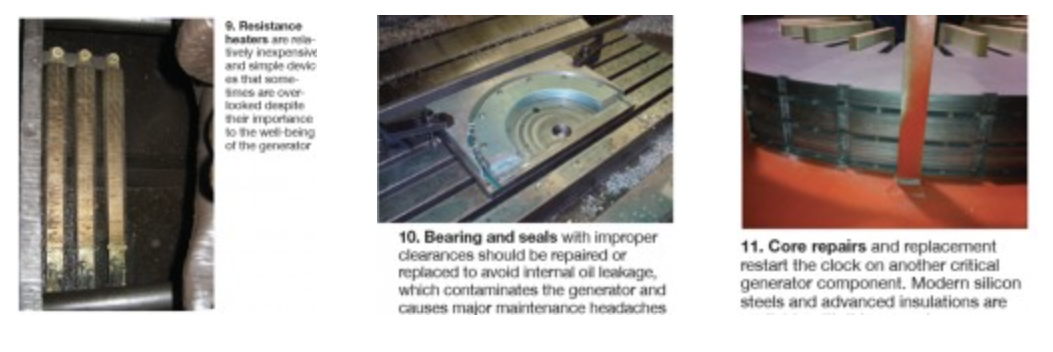
Resistance heaters. The operation of resistance heaters should be verified (Fig 9). If the generator stator temperature is maintained above the dew point, condensation is prevented. RTDs and heaters should be tested and replaced when not functioning properly.
Bearings and seals. It is always good practice to ultrasonically inspect the bearing babbitt for proper bonding to the shell and to check bearing clearances. Seals should be tight to keep moisture out of the bearing system, and prevent oil leakage into the generator stator (Fig 10).
Core repairs and replacement. Your vintage generator probably still contains the original stator iron. Stator cores can be completely replaced in the field (Fig 11). In the past, stator laminations were punched using large dies. Today, laminations can be cut precisely and quickly using laser technology. Modern silicon steels also are much more efficient and reduce core losses. Plus, the latest inter-laminar insulation coatings are electrically superior and mechanically tougher than those of yesteryear.
 Wrap-upThe new iron can be installed with the stator positioned vertically, or horizontally using spider-like fixtures and blocks of hardwood to align the new laminations during stacking. The iron is compressed using hydraulic jacks as the core is built out. A new stator core will provide associated renewed service life, as well as a degree of uprate potential.
Your vintage generator may be a classic—between 20 and 40 years old—perhaps even an antique (over 40). But it was designed conservatively, constructed with craftsmanship, and built to last. Maintaining your unit in top condition begins with proper operation; know your capability curve and abide by its parameters. Conduct routine electrical, mechanical, and NDE assessments. Perform all associated maintenance. Remember that generator longevity demands clean and tight windings. Take advantage of today’s upgrades when the economic equation points in that direction; extend your vintage Frame 5 generator’s life and possibly increase its capacity. With such enhancements, your classic will stand the test of time. CCJ
More from “The Venerable Frame 5 Special Report“