


New user group focus on the integrated plant, staff, not specific equipment
 Planning for the Combined Cycle Users Group’s second annual meeting in Orlando, October 16-19, is well underway, reports Calpine’s Larry Small, the organization’s chairman. Recall that the CCUG was launched last year as an independent, user-directed group to serve owner/operators of combined-cycle, combined heat and power (CHP), and cogeneration plants. It is distinguished by the logo in the sidebar and not affiliated with any other group of the same or similar name, nor is it associated with any other industry event.
The CCUG’s meetings are dedicated to formal presentations and attendee-driven discussion sessions focusing on the design, construction, operation, and maintenance of the integrated plant. Additional topics addressed include NERC and other regulatory impacts on plant operation, environmental rulemakings, plant mods to achieve performance goals, safety initiatives, professional development, skills training, etc. There is no vendor fair associated with this event.
Presentation topics at the group’s inaugural conference, Oct 31-Nov 2, 2011, in San Antonio, included the following:
- Cycle design improvements to boost availability, improve performance, reduce emissions and costs.
- Planning for 2020.
- High-energy piping inspection and repair.
- Water conservation and treatment.
- Combined-cycle operating challenges and changing paradigms.
- Challenges of modern control systems: Cyber security and beyond.
Summaries of the 2011 presentations are below. If you have questions or other thoughts on these topics, and are employed by a gas-turbine owner/operator, access the combined-cycle community by visiting www.ccusers.org. PowerPoints for most presentations can be found at that site as well.
Balancing act: Efficiency improvement versus cost reduction
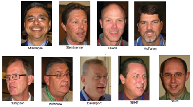
Kajal Mukherjee, engineering technical director for WorleyParsons, was the ideal opening speaker. His broad knowledge of plant design and encyclopedic memory brought attendees up to date on OEM offerings and possible plant enhancements and how their financial returns compared.
Mukherjee took questions as he spoke, thereby expanding the scope of his prepared presentation, which was co-authored with Manager of Projects Andy Donaldson. This flexible format allowed some attendees to benefit from “free consulting.” The information exchange was robust and the opening session ran more than a half-hour longer than planned.
Details provided on advanced gas-turbine designs allowed participants to compare the latest models of Alstom, GE, Mitsubishi, and Siemens F-class engines by firing temperature, cooling system, combined-cycle arrangement, output, heat rate, and experience. A similar comparison was possible among G air- and steam-cooled offerings, H-class engines, and Mitsubishi’s J-class machine. A review of quick-start features, emissions, low-load parking, turndown, and ability to accommodate fuel variations generated considerable discussion.
Some of the data gleaned from the Mukherjee/Donaldson table:
- Firing temperature typically is 2550F for the latest F-class machines, 2730F for G- and H-class engines, and 2910F for the Mitsubishi J.
- Nominal combined-cycle outputs in a 1 x 1 arrangement are 275-330 MW for F-class gas turbines, 400 MW for G- and H-class, 450 MW for the J. For 2 x 1 plants the respective outputs are 550- 660 MW, 800 MW, and 900 MW.
- ISO heat rates based on the lower heating value of fuel compare this way: F, 6000-6100 Btu/kWh; G, 5900; H, 5830; J, 5750.
Another segment of the Mukherjee/Donaldson presentation compared generation options in terms of performance, cost, and emissions, much of this information taken from government reports. A simple-cycle advanced GT was the least expensive of the 22 alternatives evaluated, coming in at just under $700/kW; municipal solid waste was the most expensive at more than $8000/kW. Advanced pulverized coal with carbon capture and storage (CCS) and nuclear were near the middle of the pack with costs of about $5100/kW and $5300/kW, respectively.
An F-class combined cycle burning natural gas and equipped with CCS offered the lowest emissions: 87 lb CO2/MWh (gross); 0.06 lb NOx/MWh (gross). The same unit without CCS released 790 lb CO2; NOx emissions were unchanged.
Where water use is a major concern, the conventional F-class combined cycle burning natural gas offered the lowest consumption at 3.3 gpm/MW (net). Water consumption for a subcritical pulverized-coal-fired plant would be nearly five times that amount.
Market drivers and trends cited by the WorleyParsons engineers included the following:
- New natural-gas resources and stable gas prices will continue to support generation-capacity additions with combined-cycle plants.
- Combined-cycle additions also will be favored for their shorter construction schedule, higher efficiency, lower emissions, smaller carbon footprint, lower water consumption, and lower capital investment compared to alternative generation options.
- Supplemental firing provides relatively low-cost incremental capacity to support peak demand requirements with moderate heat-rate impact.
- Steam temperatures above 1050F for advanced combined-cycle plants are compatible with today’s HRSG and steam-turbine technologies.
- Dry or hybrid cooling is expected to gain market share because of growing water conservation concerns.
- Fast start/rapid response plants are gaining popularity in some areas to (1) increase ancillary services revenue, (2) reduce startup emissions and fuel consumption, and (3) move up in the dispatch order to increase revenue.
- Capacity factors of combine-cycle plants are expected to increase.
Mukherjee urged attendees to pursue efficiency improvements because of their positive impacts on ecology and economics. He offered this example: A 50-Btu/kWh improvement in net plant heat rate (higher heating value basis) for a typical 600-MW, 2 x 1 F-class combined cycle reduces fuel consumption by 135,000 million Btu/yr, CO2 emissions by over 8000 tons/yr, and annual fuel cost by about $690,000. The foregoing numbers assume operation for 6000 hr/yr, 92% plant availability, $5 natural gas, and CO2 emissions of 810 lb/MWh (net).
The gas turbine is the “master” in a combined-cycle plant, the engineer continued, and it plays the most important role in efficiency improvement. However, rigorous engineering is critical to extracting maximum efficiency from the balance-of-plant design. He presented a checklist of areas demanding your attention at the design stage, and during operation, including these:
- HRSG pinch points, approach, pressure drops.
- Main and reheat steam system operating pressures and temperatures.
- Steam piping and reheater circuit pressure drops.
- Steam turbine design and backpressure.
- Cooling-tower approach and range.
- Condenser terminal temperature difference.
- Reduction of unnecessary margins on equipment rating.
- Use of premium-efficiency motors.
- Pressure drops in all piping systems.
In closing this portion of his presentation Mukherjee noted that the individual impacts may not be significant, but in combination they can provide respectable performance improvements. He urged conducting design work in close coordination with equipment vendors to ensure commercial availability and maturity of the proposed design options. Then he stressed that nothing comes free. Capital cost increases are associated with most performance improvements and a cost/benefit analysis is necessary.
The staffing conundrum
Ask a roomful of powerplant O&M managers what their biggest challenge is today and staffing is virtually sure to be at the top of the list for more than half of those present. There are many reasons for staffing concerns, particularly at generating facilities powered by gas turbines: ageing workforce, staff reductions driven by headquarters directives, salary caps, no pool of experienced prospects, etc.
A big unknown at many plants is how the facility will operate five or 10 years down the road: Will they be peaking, base load, tied to ancillary services agreements? What will plant personnel be responsible for? Will they do all O&M, or just operations and light maintenance, with the heavy maintenance being handled by outside contractors? If you cannot answer questions such as these confidently, how can you hire and retain the right people?
NV Energy’s VP Generation Kevin Geraghty made “right-staffing” a priority and launched a fleet-level initiative, “Workforce 20/20,” last year to prepare the utility’s generation department for the future. Peter Steinbrenner, manager of plant engineering and technical services, and a key leader on the nine-committee task force assembled to develop a plan for accommodating both the “silver tsunami” and an evolving generation portfolio, explained the process to CCUG attendees.
Simply put, Steinbrenner said, the goal is to create a system to continuously evaluate, define, and produce the competencies and skills necessary to meet the company’s business needs. The process selected relies on Hoshin methodology. According to Wikipedia, Hoshin is intended to help an organization do the following:
- Focus on a shared goal.
- Communicate that goal to all leaders.
- Involve all leaders in planning to achieve the goal.
- Hold participants accountable for achieving their part of the plan.
Steinbrenner was well prepared and shared with the group NV Energy’s challenges with respect to changes in operating technology, increased regulation, renewables generation, and economic pressures. He also put up a chart with numbers of potential retirements within one year, between two and five years, and those five years or more away for key positions, including: welder, technician, supervisor, operator, mechanic, engineer, apprentice, etc. That started a dialog between attendees and speaker that continued for several minutes. It appeared that most companies had not pursued such studies with comparable rigor.
Steinbrenner continued with an overview of the task force and its three-dozen participating employees, which are aided by an outside facilitator. One of the committees, he said, is responsible for determining what energy supply will look like nine years from now; another is charged with identifying the types of service-level agreements that may be required for internal/external services providers; yet another is responsible for creating job-analysis questionnaires and job descriptions for 2020.
Considerable discussion developed around Steinbrenner’s explanation of so-called “core work,” which is critical to Workforce 20/20 activities. He defined core work as all the duties required for NV Energy employees to produce electric power that cannot be obtained externally without increasing cost, reducing quality, or compromising reliability. More specifically, core work:
- Is critical to the business.
- Requires skills that must be developed internally and cannot be readily contracted.
- Is work that the utility can perform more cost-effectively and with much higher quality than external resources.
- Is highly specialized and requires skills very specific to the business of generating electricity.
- Is work that would put the company at risk if not performed to the highest standards of reliability and quality.
Then the speaker asked attendees what their criteria were for non-core work after explaining NV Energy’s:
- Work that can be easily contracted.
- Work that can be performed more cost-effectively by contractors.
- Work that is more like a commodity and is not highly specialized.
- Highly specialized work—such as engineering design—that the company does not do consistently and cannot maintain expertise in the area.
Next, Steinbrenner asked the participants when they contract work, first offering his company’s guidelines:
- During vacancies until filled.
- During peak workloads.
- When the company does not have the ability to maintain expertise internally equal to or better than that which can be purchased elsewhere.
- When safety, environmental, and OSHA compliance issues must be quickly addressed.
The give and take was significant, with both speaker and attendees learning from each other. On several occasions, Steinbrenner had to put down his microphone to make notes based on the experience of others in the room.
Steinbrenner closed his presentations with a list of key assumptions for the Workforce 2020 effort, including the following:
- Hire journeymen and train them to be operators.
- Contract most heavy maintenance.
- Consolidate control rooms.
- Convert maintenance managers into asset managers.
- Contract O&M for windfarms.
- Create one plant supervisor classification.
- Self-perform core work, contract non-core.
Several attendees acknowledged that their companies were already doing some of these things and considering others.
Tony Wiseman, a training director for Progress Energy at the time of the meeting, led a discussion on the practical challenges associated with the hiring and training of craft personnel. First, he pointed out the following differences in personal values for each of the four generations that may have to coexist in any given plant:
- Traditionalists (born 1928-1945) subscribe to conformity, stability, upward mobility, security, and economic success.
- Boomers (born 1946-1965) are characterized by personal and social expression, idealism, health and wellness, and youth.
- Generation X (born 1966-1979) are defined by their free agency and independence, street smarts, friendship, and cynicism.
- Generation Y (born 1980-2000) believe in hope about the future, collaboration, social activity, tolerance for diversity, and family centricity. Regarding the last characteristic, Gen Ys see their parents as role models and heroes. They trust authorities (such as teachers and police) in addition to their parents.
Next, Wiseman compared traditional craft structure to what’s needed in today’s combined-cycle plants. Traditional structure has a person trained as a mechanic, electrician, I&C tech, or operations tech—all separate and distinct crafts that begin at the apprentice position and progress through an intermediate stage to journeyman.
Skill overlap is required today to develop the multi-craft technician conducive to efficient plant operation. This is accomplished by having individuals specialize in one of the four disciplines noted above, and achieving journeyman status in it, while becoming proficient in the others.
To maximize the probability of success in personnel development, Wiseman suggested a multi-step plan that begins with a new-employee assessment. It consists of a written exam as well as an evaluation of deck-plates job skills. After the craft path is decided, specific training is initiated and the employee begins on-the-job training as an auxiliary operator. Simulators help here and eventually can bring the new hire up to the skill level required of a control room operator.
In time, a “jack of all trades and master of one” is molded. Maintaining the skills taught requires an ongoing program of evaluation and refresher training.
High-energy piping
Two solid presentations got the piping session rolling right after lunch on the first day—one on P91 piping fabrication guidelines by Dr David Buzza, senior engineer (metallurgist), for AEP Region 7; the other on risk-based assessments of high-energy piping systems by Consulting Engineer Jonathan McFarlen of M&M Engineering Associates, Austin, Tex. Comprehensive Q&A and discussion followed in the two-hour session.
Buzza reminded the group that Grade 91 material was developed for high-temperature service, its allowable stress being 2.5 times greater than that for P22 at 1080F. Thus P91 is much lighter than P22 for a given application by virtue of its thinner wall. This metallurgist, who spends a considerable amount of time on the deck plates elbow-to-elbow with plant personnel, shared his extensive practical knowledge on the set-up and control of post-weld heat treatment (PWHT) to achieve desired material hardness of 190 to 250 Brinell (HB) for components, 190 to 280 HB for welds.
Buzza reported on findings in both small- and large-bore piping (dividing line is 4 in.) at three combined-cycle plants in the Midwest. Both hard and soft components were identified with small-bore pipe as well as hard socket welds. Problems with large-bore piping focused on hard attachment welds and soft components (mostly elbows).
Well over a dozen components at the three plants had hardness readings from 316 to 390 HB, making them susceptible to overload or creep failure because of improper metallurgy. More than 10% of the socket welds at the plants revealed high hardness (300 to 439 HB). Numerous soft components (less than 165 HB) were found at two plants.
Improper PWHT is the root cause of P91 fabrication issues. For example, hard components are the result of exceeding the lower critical temperature (LCT) during PWHT followed by rapid cooling. Hard welds occur because the PWHT temperature at the weld never reached the hold temperature. Soft components mean PWHT temperature exceeded the LCT and that was followed by slow cooling; or PWHT hold time was excessive.
Critical to proper PWHT is sufficient thermocouples (t/cs). For example, when welding an elbow in to a drain line, t/s are recommended in the pipe segments upstream and downstream of the elbow, in the pipe elbow itself, and at the inlet and outlet welds where the drain piping lines up with an elbow. Proper heat treatment results in good hardness readings.
PWHT also must be monitored carefully during shop fabrication. For new units, drain pipe spools may be fabricated in the shop and then shipped to the field for install. It seems logical that under controlled shop conditions a good specification is all that’s needed to assure proper welding and heat treatment. But don’t believe it; take nothing for granted when it comes to P91.
The speaker spoke of that lesson learned in the fabrication of 2-in. socket-welded P91 pipe spools. After welding, the pipe spools were loaded into an induction furnace for heat treatment. Records showed that the target temperature and hold time had been achieved. Good thing hardness checks were in the spec: 100 of the 170 welds were too hard. Conclusion drawn was that the furnace temperature did not accurately reflect the actual weld temperature during the heat-treat process.
Keys to proper fabrication of P91 were discussed among the users. Here’s one procedure, something you will not find in the ASME Boiler & Pressure Vessel Code.
1. Check incoming material.
- Ratio of N:Al on the material test report (MTR) should be greater than 4:1 and under no circumstances less than 2.5:1. It was said that the N:Al ratio is important because you want nitrogen precipitates, not aluminum.
- Hardness on the MTR, supported by in-house test results, should be 190-250 HB; 220 HB is optimal because hardness decreases with each PWHT cycle.
2. Specify verified heat-treat procedures.
- Follow AWS D10.10, which provides guidance on the number of control zones based on pipe diameter, heating-blanket length, monitoring t/cs.
- Use heat-treat set-up sheets. Procedure should specify ramp rates, hold times, temperatures, placement of heating circuits, control t/cs, etc.
- Review heat-treat set-up sheets. For example, check that thick and thin sections are on different heating circuits; heating pads are in contact with the pipe (you don’t want air gaps); control t/cs are near the center of the pad and at the location expected to be the hottest, etc.
3. Confirm proper heat treatment through hardness testing by a qualified technician. A rule of thumb: Base material hardness should be with 20 Brinell hardness points of initial readings.
M&M Engineering’s McFarlenhad a great deal of practical information to share with the group. He began with a risk-based evaluation of high-energy piping (HEP) and moved from there into an assessment of HEP. McFarlen said that although HEP is not formally defined by the ASME Boiler & Pressure Vessel Code, it generally refers to main steam, and hot and cold reheat—and more and more, boiler feedwater piping and steam extraction lines.
Risk is not constant over time, he stressed, adding that risk assessments must be revisited periodically to account for such things as the actual history of temperature excursions, age of the piping system, last inspection scope and results, etc. Key steps in assessing risk are the following:
- Define system boundaries.
- Catalog components in the defined system.
- Identify failure modes for each component.
- Establish failure probability based on industry experience. Example: Failure possibly occurring once per lifetime has a probability of 0.01 to 0.001.
- Establish the consequences of failure, usually in terms of financial impact and/or downtime.
- Calculate baseline risk per component/failure mode combination.
- Determine influential factors and apply weighting factors—that is risk modifiers—and recalculate risk.
- Prioritize inspection activities for each component based on risk using prudent engineering judgment within fiscal constraints.
A review of damage mechanisms was next. McFarlen presented a handy table of nine mechanisms, where they were likely to be found, and the nondestructive examination techniques for identifying them. For example, high-cycle fatigue generally is associated with branch/tee welds. Visual, mag-particle, and ultrasonic inspection technologies are used to identify HCF.
McFarlen’s segment on HEP assessment acknowledged that these piping systems, while not inspected routinely, cannot be taken for granted. Any pressure release could cause serious damage and/or personnel injury. An evaluation program encompassing the piping system and its supports allows an assessment of boiler external piping for use as the basis for continued service.
Piping support basics was of primer of value to many in the room. McFarlen addressed the following:
- Flexible hangers. They are used when vertical travel of a piping section is required because of thermal expansion.
- Rigid hangers—including rod hangers, stanchions, slide plates, spider guides, travelers, etc. They are used to support a section of piping where no or minimal vertical expansion is expected.
- Snubbers, which are used to arrest dynamic loads from hammer events or seismic loading.
Hangers generally are over-designed, the piping expert said, but problems can and do occur. For example, malfunctioning supports can lead to excessive localized loads and subsequent piping damage. Flexible hangers are prone to internal damage—such as corrosion, debris buildup, nesting birds, etc—which can arrest or restrict travel.
Your piping-system assessment should include a visual inspection and hanger survey. Observations such as areas of uplift or sag, interference, corrosion, etc, should be noted and investigated. Deformation and interference may indicate excessive loading; wetted areas may pinpoint areas of external corrosion where crack initiation may nucleate.
Survey hangers during hot and cold walk-downs; document hanger positions with photographs and written reports. Be sure to describe physical condition of the hangers in adequate detail. After taking hanger readings, compare the data collected to the “as-design” setpoints.
You may find that based on walk-down observations, a pipe stress analysis may be required. And based on the results of that work, NDE may be necessary to accurately determine the condition of your piping.
Corrective measures can be as simple as adjusting hangers, which is not always so simple. To illustrate: Hangers that travel less than designed/expected may require load testing. Depending available space, testing can be done in place with a dynamometer to assess functionality. Sometimes, just “working” the hanger during testing can clear out debris and return the component to full functionality.
Bottomed-out or topped-out hangers may merit NDE of attachment points and circumferential welds. Stress analysis sometimes is necessary to justify NDE. Sections of pipe with deformed supports should be carefully inspected with the latest NDE tools without hesitation.
McFarlan encouraged participants that a visual examination/hanger survey of HEP is a good start to ensuring piping reliability and that plant personnel can do this with some fundamentals training. Higher-level evaluations (stress analysis and NDE) likely will require outside support. For more background on the subject, access “How to assess the health of high-energy piping systems,” 1Q /2009, p 104.
Water conservation, treatment
The Monday afternoon session on water conservation and treatment featured as speakers two of the electric-power industry’s top chemists: Jim Witherow, executive chemist, Scientech, a business unit of Curtiss Wright Flow Control Co, and Dan Sampson, senior technical consultant, WorleyParsons. The former focused on boiler-water chemistry, the latter on water conservation.
Witherow opened his presentation by outlining the following goals for an HRSG chemical treatment program:
- Provide optimized corrosion protection to all wetted surfaces.
- Minimize operator intervention.
- Support water conservation principles.
- Be cost effective.
His coverage of factors affecting water usage was brief. Witherow made it clear that if boiler chemistry were maintained within accepted industry specifications, makeup requirements generally would be acceptable. Blowdown, he said, must increase to purge contaminants allowed into the steam cycle as well as those produced in the boiler and other equipment when system chemistry gets out of control.
Poor quality makeup and condenser tube leaks, for example, forces plant operations personnel to increase blowdown to control silica, chlorides, sulfate, conductivity, and pH. Control of particulates from general corrosion and flow-accelerated corrosion (FAC) also is managed by regulating blowdown.
Witherow next introduced all-volatile treatment (AVT), plus a solid alkali program to increase corrosion protection in evaporator drums, as the foundation of sound water chemistry program. For all-ferrous systems typically identified with combined-cycle plants he suggested AVT(O), with ammonia as the neutralizing amine. Elevate feedwater pH to 9.2 minimum, the chemist recommended, do not use chemical reducing agents, and hold dissolved oxygen to between 1 and 10 ppb.
An oxidizing environment, Witherow said, particularly one with a pH of 9.2 to 10, reduces iron solubility. That offers protection against FAC, most often found in LP evaporators and economizers with fluid temperatures typically ranging from 250F to 350F. Metal thinning occurs in areas where turbulent flow is present—such as where piping diameter changes, where there are bends and elbows, and where thermo-well penetrations exist. Mild steel wears relatively fast, Witherow added, and suggested use of T11 and T22 to prevent its occurrence.
However, AVT is necessary for copper-bearing systems, he reminded. Minimize dissolved oxygen with a chemical reducing agent, minimize the addition of a reducing agent to maintain the desired oxygen level, and accept a slightly lower pH control range. Its important to closely monitor piping and tubing for FAC; replace affected components with ones made from chromium-bearing alloys.
Solid alkali treatment for evaporator drums increases the tolerance for contamination and contributes to reduced rates of blowdown. It also acts as a buffer to minimize pH swings. The addition of sodium phosphate to LP, IP, and HP evaporator sections, Witherow said, reduces FAC, promotes pH stability, and contributes to corrosion protection.
The chemist talked about two forms of phosphate treatment: coordinated/congruent and trisodium alone. The former is the classical, high-level treatment with varying mixtures of mono, di, and trisodium phosphates. It is beneficial for changing pH when contamination is high. Not usually recommended for HRSGs; may lead to additional blowdown. There are two ranges of trisodium phosphate treatment depending on the level of contamination level. One provides 0.3 to 3 ppm phosphate; the high range, 3 to 10 ppm of phosphate.
Disadvantages of phosphate treatment, reminded Witherow, is carryover and hideout. The former can cause superheater and steam-turbine damage. The latter reflects the lower solubility of phosphate as temperature (pressure) increases and can lead to pH and conductivity instability as well as promote under-deposit corrosion.
Sampson discussed the water-supply challenges facing the electric power industry going forward and commented on the options available to generation companies for minimizing consumption. His back-of-the-envelope assessment for a combined-cycle plant equipped with a conventional mechanical-draft cooling tower: 60% to 90% of total plant water consumption is unrecoverable. Losses include cooling-tower evaporation and drift, gas-turbine power augmentation and evaporative cooling, steam losses, etc.
By subtraction, recoverable/recyclable water streams for the same plant amount to 10% to 40% of total plant water consumption—including cooling-tower and HRSG blowdown, pretreatment system wastewater, plant service water, leaks, and drains.
Rules governing water use and discharge keep changing and virtually every new regulation impacts a powerplant’s treatment and consumption strategy. Sampson said that permitting bodies may require consumptive reduction or recycled water use to balance increases in water withdrawls to accommodate population increase, changes in weather patterns (droughts), etc.
He also mentioned limits on total dissolved solids (TDS) for plant discharges to publicly operated treatment works (POTW) and natural waterways as impacting plant water-use and treatment strategies. New ion-specific limits on phosphates, sulfates, etc, are an overlay on those rules.
The portion of Sampson’s presentation on water conservation myths offered an opportunity for attendees to rethink their “beliefs.” Perhaps the three biggest misconceptions, he said, are these:
- Higher cycles of concentration can save lots of water.
- Zero-liquid-discharge (ZLD) systems can save lots of water.
- Once-through cooling uses lots of water.
Regarding the “higher cycle myth,” Sampson offered these numbers: A 2 x 1 F-class combined cycle with a mechanical-draft tower evaporates 2000 gpm. Makeup is 3000 gpm at three cycles, 2250 gpm at nine cycles. Thus, tripling the number of cycles saves only 750 gpm (25%). The same plant with an air-cooled condenser (ACC) averages 200-300 gpm of total makeup (not just the tower)—a saving of 2700-2800 gpm (90%).
The “ZLD myth” parallels the higher-cycles myth, he said. ZLD recovers 97% of cooling-tower blowdown, lowering makeup from 3000 gpm to slightly more than 2000 gpm at three cycles of concentration. The ACC option offers a much greater saving in water. Plus, you don’t have to deal with the migraines associated with many of the ZLD systems.
Once-through cooling is [IT] non-consumptive [RM] and fits the same water-usage profile as an ACC. However, chemicals and heat are added to the water prior to its discharge from the plant. Once-through cooling is increasingly prohibited by permitting bodies.
Summing up the myths, Sampson noted that air-cooled plants minimize water consumption but ACCs can add significantly to both capital and operating costs, once-through is very dependent on location/permitting, and ZLD is not worth the effort and cost. What’s left? Recycled water, which is what the consultant believes is the best option by far—especially when it is coupled with efficient use of water onsite.
Recycled water offers the following benefits, Sampson said:
- Reduces plant operating cost because recycled water is less expensive than city water and the treatment costs are about equal.
- Reduces the demand for potable water.
- Makes use of a resource that’s often wasted.
- Minimizes environmental impact.
- Provides a virtually drought-proof water supply.
When using recycled water, Sampson continued, focus on the cooling tower. Do not use it to make demin water; it will produce operational headaches. Use potable water to make demin water and send both demin-system (reverse-osmosis rejects, etc) and low-TDS waste streams to the cooling tower as makeup.
The balance of the consultant’s presentation covered system/equipment changes (mechanical, operational, and chemical) needed to make the use of recycled water a positive experience. Final suggestion: Don’t transition to recycled water without a detailed roadmap and monitoring plan.
Permitting challenges
Kevin Davenport’s presentation on permitting challenges for combined-cycle facilities was an eye-opener for all attendees who hadn’t had recent involvement in the design of new units or in the upgrade of existing gas-turbine assets. Davenport is a specialist in air permitting and compliance for TVA and deals with regulatory challenges daily.
He began with the requirements for New Source Review (NSR) and Prevention of Significant Deterioration (PSD). The first pertains to a new or modified source—not routine maintenance, repair, or replacement—that results in a significant increase in emissions. Note that “modification” can be a physical change or a change in the mode of operation.
Important: For non-attainment areas, NSR requires the Lowest Achievable Emission Rate (LAER), analysis of alternative sites, ambient modeling, offsets, EPA input, and public hearing.
PSD for attainment areas requires Best Available Control Technology (BACT), ambient modeling, impact analysis, and input from EPA.
More detailed requirements include the following:
- For combined-cycle plants, SO2, lead, and sulfuric-acid mist should not be of concern because emissions typically are below the threshold requiring BACT/LAER analysis.
- NOx, VOC, all PM and CO require BACT/LAER analysis. Davenport stressed that limits continue to drop and averaging times are getting shorter. Examples: (1) NOx BACT is at 2.5 ppm today. (2) The 8-hr emissions average that you might remember is disappearing; a 3-hr average is more typical and some states are already at 1 hr. (3) CO BACT is less than 10 ppm.
- NOx, all PM, and CO must be modeled to determine their impacts on air quality.
- Under new EPA requirements, CO2 will require BACT. Carbon capture is a technology which must be evaluated; however, it should fail the economic feasibility test unless you have a close neighbor that can use the CO2. Heat rate is another important consideration, the group was told.
- Netting can work to your advantage if, for example, the combined cycle is located on the site of a retiring coal-fired unit. Recall that NSR netting is the procedure for determining if the net emissions increase is significant and subject to the major non-attainment NSR requirements.
Davenport next commented on rapid start, which was the subject of a later presentation. He said that rapid starts lower emissions of NOx, VOCs, and CO during the startup cycle because the catalysts come to optimal temperature sooner. Your permitting authority may requireconsideration of rapid start as a BACT (depending on location), Davenport continued.
He added that since BACT is an economic evaluation, the cost adder (capital and O&M) for rapid start and the anticipated dispatch of the facility will determine if it is required.
Details on greenhouse-gas permitting followed the rapid-start discussion. Davenport said EPA is requiring BACT for CO2 on new or modified sources where emissions of the pollutant increase by 75,000 tons/yr or more. He added that BACT will be included as an operating requirement in permits and would most likely be couched in terms of lb CO2/MWh. It was said that EPA has proposed 800 lb CO2/MWh for a base-load unit, which generally is considered a relatively low number among users.
A general feeling was the permitting authorities are not currently conversant on many factors affecting the heat rate of gas-turbine-based plants. This suggests that users be prepared to answer questions related to the following:
- Number of startups and shutdowns.
- Low-load operation and/or short run times.
- Operation on automatic generation control.
- Capacity factor.
- Seasonal effects on heat rate.
- Size and anticipated operation of duct burners.
- Degradation of equipment over time.
- Operation in a simple-cycle mode if permitted. Be sure to negotiate different limits for simple- and combined-cycle operation.
Certainly the most interesting part of Davenport’s presentation was a discussion of TVA’s negotiations with EPA in the permitting of combined cycles, one at a coal-fired plant scheduled for closing. Consider attending the next meeting of the Combined Cycle Users Group so you don’t miss such valuable insights.
Fast-start/fast-ramp combined cycles to debut in California. California’s Renewable Portfolio Standard (RPS) demands that 33% of the state’s kilowatt-hours come from renewable resources by 2020—the most stringent such requirement in the nation. Integration of high percentages of renewable energy with electricity from conventional resources requires flexible generating assets fired by fossil fuels. Fast-start/fast-ramp simple- and combine-cycle gas-turbine capability is expected to be part of the mix.
There are plenty of simple-cycle peaking engines available to back up intermittent renewables, but no combined cycles in the US capable of fast-start/fast-ramp operation at this time. The first two such plants are under construction in California: the nominal 300-MW, 1 x 1 F-class Lodi Energy Center nearing completion about 40 miles south of Sacramento, and the 624-MW, 2 x 1 F-class Oakley Generating Station (formerly known as Contra Costa) in the early stages of construction about 50 miles northeast of San Francisco.
The CCUG steering committee invited Ken Speer, assistant GM, Northern California Power Agency, to address attendees on the challenges and expectations associated with building the nation’s first fast-start combined cycle. Speer, who came to NCPA from independent power business, is a power professional who sees the value of Lodi in being able to both follow wind and to operate as an efficient combined cycle in base-load service.
When the facility begins operating next summer it will be the most efficient natural-gas-fired powerplant in Northern California. A big benefit is that the agency’s 14 member companies and two associate members will reduce their greenhouse gas emissions by up to 70%.
The power island is a Siemens single-shaft Flex-Plant™ 30, capable of delivering about 200 MW to the grid within 30 minutes (hot/warm start), 70 MW in 10 minutes. Bear in mind that short startup times reduce significantly startup fuel consumption and emissions. Fast start is enabled by a once-through Benson arrangement in the HP section of the triple-pressure, reheat heat-recovery steam generator. The IP and LP sections have steam drums like conventional HRSGs.
Best available control technology is applied to limit emissions of NOx15 to 2 ppmvd, CO to 2 ppm, volatile organic compounds to 1.4 ppm, and ammonia slip to 10 ppm. Recycled water from the City of Lodi’s White Slough Pollution Control Facility will be used for cooling-tower and boiler makeup. Tower blowdown will be treated and pumped into an underground injection well.
Paradigm shift
In retrospect, the CCUG’s meeting in San Antonio last fall achieved its key objectives in the first day and a half: Solid presentations and discussions related to the design, operation, and maintenance of the total plant and critical systems/equipment generally not addressed by the model-specific gas turbine user groups.
But it was the final formal presentation, by Daniel Noles, manager of controls engineering, which supports TVA’s coal and gas generation fleet, that showed the user group’s value in identifying institutional changes sure to redefine how powerplants are managed in the future. TVA owns 15,000 MW of coal-fired capacity (59 units) plus 7500 MW of gas-fired capacity (87 simple-cycle engines and six combined-cycle units).
Noles’ power generation expertise brought him instant credibility. Like many in the room, his experience was in plant processes and systems such as those used in combined cycles. Noles worked for an investor-owned utility prior to joining TVA, and he approaches control systems with a focus on improving the operation of plant equipment.
Noles opened by reviewing the importance of industrial control systems (ICS) to operational excellence and defining ICS as the gamut of solutions for controlling, monitoring, and protecting plant systems—including DCS, PLCs, single-loop controllers, supervisory instruments, protective relays, emissions monitors, field devices, etc.
The pathway to his discussion on challenges associated with cyber security began with a review of existing control systems and their limitations. The DCS world began with proprietary systems and transitioned to off-the-shelf technologies, so today we have a mixture of legacy and modern systems. Many of those legacy systems or their modern replacements have been connected to other networks for supporting business decisions. While cyber security is getting more focus in recent years, the interconnection of systems often leads to increased security risks.
Noles next discussed what he termed “general” control-systems challenges. System complexity was first on the list, and Noles stated that complexity often increases security or other risks related to control systems. Noles also noted that interconnection of networks, while providing opportunities for business cost savings, can lead to vulnerabilities if not properly secured.
Finally, he discussed challenges related to workforce demographics and trends. Challenges include identifying expertise, roles, and responsibilities necessary to properly maintain and secure control systems. While many technologies in modern control systems are similar to those used in IT systems, the two environments have significant differences and each require unique skill sets. Noles emphasized the need for collaboration among organizations such as IT, control system support, corporate compliance, and others.
There are still many challenges in the electric utility industry with regard to securing control systems. Several organizations such as DHS (Dept of Homeland Security), NIST (National Institute for Standards and Technology), and ISA (International Society of Automation) have published best practices and standards on the subject.
While the industry security standards exist, the primary regulatory compliance standards known as NERC CIP (Critical Infrastructure Protection) are still evolving rapidly in comparison to the timeframe required for implementing effective compliance program. The current standards, CIP version 3, have been implemented at many utilities; however, there is uncertainty about whether the next step will be version 4, which is near final approval, or version 5 which could be approved by late 2012.
Noles provided examples of recent cyber events and groups responsible for them. Everyone present gained a new appreciation for the realities of cyber security risks that exist today. In recent years, high profile targets have often included financial institutions and governments, but critical infrastructure such as power and water industry control systems have increasingly become targets for cyber attacks.
They can be launched by disgruntled employees, outside individuals, organized crime, terrorist groups, or other governments. While the potential for cyber attacks is a serious threat to the country’s infrastructure and economy, he noted that effective defense-in-depth strategies can be deployed to manage the risk.
Examples of best practices and essential security defenses were highlighted such as:
- Standardization and lifecycle planning , which reduces the complexity of security requirements.
- Network segmentation, which limits access points to control systems.
- Logical and physical access controls—such as card readers on doors or user passwords on devices.
- Backup and recovery of applications and data.
- Deployment of malware defenses, such as anti-virus programs.
- Security monitoring systems to detect abnormal network traffic.
- Incident response and forensic plans for preparedness in the event of a cyber attack.
- Management of change, which is required for compliance but often pays dividends in plant reliability.
- Information protection to minimize access to your control-system configuration details.
- Device and software inventories , which are required in managing security and documenting compliance.
- Secure configurations for hardware, software, and network devices.
The conclusion provided practical advice on building an effective cyber security program to minimize risks. One of the first and most important steps is to identify an executive sponsor who will ensure the program receives adequate focus and funding. Early stages of the program efforts should include assessments of current security practices, organization resources, and security awareness training. Establishing an effective and sustainable cyber security program will require significant funding and commitment.
He closed by emphasizing the need for a strategic program that balances security, compliance and business objectives. In his final remarks, Noles said, “We must not lose sight of the ultimate goal for control systems and cyber security programs [yes, including compliance] which is to sustain the safe and reliable operation of generation, transmission, and distribution assets that benefit each of us in our daily lives.” CCJ
Steam supply set-up for a fast-start combined cycle
The technology built into the Lodi Energy Center allows for faster starting of the gas turbines by mitigating restrictions normally associated with operation of the heat-recovery steam generator (HRSG) and steam turbine. Traditionally, gas turbines are stared up slowly, with long hold times at low-load points to limit stresses in the high-pressure steam circuit.
The Flex Plant 30 design avoids previous restrictions by eliminating the high-pressure steam drum from the HRSG. The once-through Bensen boiler arrangement used in the HP evaporator has two sections. After partial evaporation in the first section, the steam/water mixture passes through a downcomer and distribution device before entering the second section.
The star distributor prevents separation of the steam/water mixture and allows uniform distribution of the fluid in HP evaporator 2. The degree of superheat at the outlet of the second section varies depending on gas-turbine load and ambient conditions, and is controlled by feedwater flow. The slightly superheated steam exiting HP evaporator 2 flows through a steam separator to the HP superheater.
Lodi also has an auxiliary boiler to provide sealing steam for the steam turbine and sparging steam prior to gas-turbine startup. This allows pulling of condenser vacuum and rolling of the steamer earlier in the startup process. HP final steam temperature is controlled using either a final stage (after the second-stage superheater surface) or interstage (between the first and second stages) desuperheater. HP steam attemperation is not required for operation at the design point.