


By Natalie Marini, HRST Inc
HRSG superheaters and reheaters are vulnerable to overheat damage that is not detectable from data typically monitored in the control room. Damage can occur even if the steam temperatures entering and leaving the attemperators and exiting the HRSG are within limits.
Stealth changes in HRSG operation, maintenance, and performance can drive overheat damage. Examples encountered by HRST engineers include the following:
- 1. Duct burners firing harder and longer than ever before.
- 2. Gas turbine (GT) upgrades that increase exhaust temperature, elevating tube metal temperature.
- 3. Original designs with very small margins between the predicted operating temperatures and the maximum design limits, significantly reducing remaining life.
- 4. Duct-burner-system mechanical degradation causing localized downstream high-temperature zones.
- 5. Removal of troublesome gas baffles, resulting in hot bypass gas that increases downstream heat transfer.
Example 1. Duct burners are firing harder because of low natural-gas prices and changes in market demand. When the burners run longer and harder, problems previously believed minor can turn into much larger ones. With frequent firing, overheating damage occurs much more rapidly. Long flames, inconsistency in flames from one side of the duct to the other, and poor distribution of exhaust flow are all common issues that can have damaging effects.
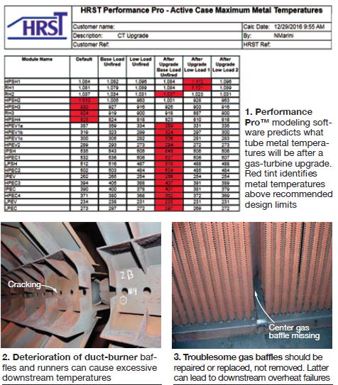
Example 2. The highest superheater and reheater tube metal temperatures in the first tube panel commonly occur during low load, unfired operation. In past analyses of the effects of GT upgrades on HRSGs, HRST engineers have found that the tube metal temperature during operation was already within a degree or two of its design limit at low-load operation—before the upgrade (Fig 1). Gas turbine upgrades change the exhaust gas flow and temperature entering the HRSG. A small increase in temperature may not seem like a big deal, but a 20-deg-F change in tube metal temperature can reduce remaining life by 50%!
Example 3. In some situations, the OEM’s original tube-metal-temperature design limit does not represent the maximum temperature a bundle should be allowed to operate at for prolonged periods. When tubes operate at temperatures approaching the upper limits allowed by the ASME Boiler & Pressure Vessel Code for that material (for example, using SA213-T91 tubes at temperatures approaching 1200F), internal oxide formation can significantly shorten tube life. When internal oxide forms, tube metal temperatures increase, further reducing the expected tube life.
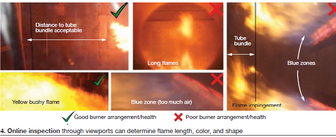
Example 4. In many HRSGs with duct burners, the baffles support the runners. As duct burners age, the baffles and runners may deteriorate and sag (Fig 2). Circumferential cracks can form in the runner, initiating at the fuel nozzles, and occasionally the runner may even split in two. The result is a flamethrower effect where the pipe has failed. In those cases where the pipe crack only goes around a portion of the runner’s circumference, a gap can open at the crack, resulting in a large flame facing downstream. This can cause localized overheating of the downstream tubes.
As prevention, annual duct-burner maintenance may be necessary to preserve the strength of the burner baffles and elements. If the duct burner is in a poor condition with buckled baffles and crack indications seen around the fuel pipe nozzles, reinforcements can be installed to strengthen the failing system and prolong life.
Example 5. Coil-to-coil baffles in the tube bundles upstream and downstream are also important components of a healthy HRSG. Large gaps between upstream tube bundles affect the exhaust-gas flow distribution at the duct burner, and can cause burner flame problems. Large gaps between the tube bundles downstream of the burner allow hot gas from the firing duct to reach downstream tubes not designed to handle the elevated temperatures.
Fig 3 shows a past inspection where a site experienced an overheat failure in a rear tube adjacent to the center gap downstream of the duct burner. The owner/operator had removed the failing gas baffles a few years prior to the failure.
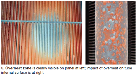
Detailed inspections are vital to identifying causes of potential overheat and avoiding problems. During online inspections, looking into burner view ports can be very telling (Fig 4). A good flame length is one that typically extends no more than one-half to two-thirds the length of the firing duct. Flames should terminate several feet upstream of the tubes. A bright yellow, bushy flame is ideal. Long skinny flames licking the tube bundle drive up local tube temperatures, often above design limits.
When performing offline inspections, examine duct-burner baffles and runners for signs of ageing to plan preventive maintenance. Failed stitch welds, sagging elements, crack indications along fuel-pipe runners, and buckling baffles all should be addressed.
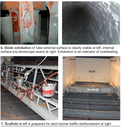
Standing from the floor looking up in the burner duct, discoloration of the tube bundle that aligns with burner-element elevations often indicates localized overheating (Fig 5). Flaking or exfoliated tube material also is an indicator. Flaking tube material can be seen in these localized zones as well as in the upper and lower crawl spaces at the header connections (Fig 6). If scale is forming on the outside of the tubes, it is most likely forming on the inside as well, particularly with grade T91, T22, and T23 materials.
Internal oxide growth decreases the internal heat transfer and causes the tube metal temperature to increase, while simultaneously reducing tube wall thickness. The increased metal temperature reduces the creep strength of the material and the thinner tube wall increases the stress. The combined effects shorten tube life significantly.
Exfoliation of internal scale also can damage downstream equipment—including the steam turbine. If superheater or reheater overheating indications are found, a borescope inspection can check the tube internal condition. The HP and/or IP sections of the steam turbine also can be inspected to look for solid particle erosion caused by oxide exfoliation.
Superheater and reheater tubes are cooled by steam flow. If steam flow is upward in the bundles just downstream of the burner, then the highest tube metal temperatures are most likely to occur near the roof. This can be exacerbated by long flames at the top of the firing duct attributed to poor distribution of exhaust flow.
If damage indications near the top are seen from the floor, then close-up inspection of the upper elevations may be warranted. Emerging drone inspection technology may be useful at this location, to avoid the steep cost of scaffolding.
Signs of overheat found? How to prevent further damage and determine the remaining life of the material? If any signs of overheat are in evidence, there are a few options available to assess tube-panel condition and determine the reduction in creep strength and remaining life of the material. A remaining-life assessment is recommended.
Inspection of the area of concern may include tube OD measurements, borescope ID inspection, and evaluation of fin condition. Tube-metal thermocouples can be added to the areas suspect to flame impingement to measure the effective tube temperature. From this, creep damage can be calculated and used to estimate the life of the equipment. Keep in mind that accurate measurements using thermocouples can be a tricky feat and proper planning and engineering are required.
Fins can be removed in the affected zones and in-situ internal oxide thickness testing can be performed. This is a UT technique and can be an effective method for evaluating the extent of tube damage.
Tube samples taken in the area of flame impingement can be assessed for creep damage.
The HRSG should be evaluated based on the new operating envelope any time a GT upgrade is planned. This can identify possible overheating beforehand, as well as other potential problems. A computerized thermal model of the HRSG can be used to set a range of acceptable firing limits and other operating parameters post-upgrade.
The duct burner should be inspected and maintained regularly by identifying and reinforcing sagging baffles, particularly with designs in which the baffles support the burner elements (Fig 7). Cover any large bypass gaps in the tube bundles with baffles.
In summary, combining longer firing hours with an aging HRSG fleet, a mix of GT upgrades, deteriorating duct burners, and tube-bundle gas-baffle failures, and you get the trending uptick in superheater- and reheater-tube overheating. Minimize long-term damage, possibly prevent it, by using thermal models to evaluate the effects of upgrades, plan maintenance in advance, and arrange for routine inspection of duct burners. Where signs of overheating are identified, have confidence that there are ways to mitigate the damage and extend remaining life. CCJ