


By David Benjamin, Contributing Editor
Editor’s note: The traditional annual conferences of all user groups serving the gas-turbine sector of the US electric-power industry scheduled between Mar 1, 2020 and Dec 31 have been canceled because of the Covid-19 pandemic. The 30th anniversary meeting of the Western Turbine Users (slated for March 29 to April 1 at the Long Beach Convention Center) was one of the organizations so affected.
Ned Congdon, PE, of HRST Inc, who was scheduled to speak in the Special Technical Presentations session on March 31, shared his talking points on problems to anticipate with ageing HRSGs with David Benjamin, an aero user, who developed the article that follows from those notes.
Many heat-recovery steam generators (HRSGs) were installed during the combined-cycle boom of 2000 to 2005, putting them roughly halfway through their 30-yr design lifetimes. While the majority of boilers experience some form of tube distress by this point, there is much that can be done to bolster their health. With good operations and maintenance informed by experienced judgment, typical design lives can be extended appreciably. It is crucial to know what to look for, and when to take corrective action. Informed forethought can help avoid costly repairs requiring extended forced outages.
Congdon highlighted the following points in his presentation, among others: Duct-burner flame management.
- Internal oxide deposits on superheater and reheater tubes.
- Duct-burner liner replacements.
- Creep-damage assessment of piping for superheated steam.
- Return-bend economizer failures.
The HRSG expert discussed the ways in which careful duct-burner flame management is essential for maintaining the health of an ageing boiler. Many simple operational parameters are commonly overlooked, and can contribute significantly to the likelihood of tube failures. It is crucial to maintain proper flame shape, to ensure a uniform vertical distribution of flue-gas, and to prevent flames from overextending and impinging on downstream tube panels.
For HRSGs with supplementary firing, the highest tube-metal temperatures and heat fluxes typically occur on the tube banks immediately downstream of the duct burners. Tube- overheating failures typically occur in this area. Sometimes, finless screen tubes with reduced heat-transfer characteristics are placed in front of the primary superheater/reheater surface to take brunt of the heat flux. In that case, the risk of a tube overheating is highest for the superheat/reheater surface immediately downstream of the screen tubes.
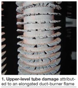
Duct-burner flames should be checked by operators during rounds. When looking through a viewport, a good rule-of-thumb is that the flame should extend no more than half to two-thirds of the length of the firing duct. Flames should be independent of each other, and should be completely horizontal. It is important all flames be of uniform length; higher elevation flames may be longer, which signifies non-uniform gas flow. The visible portion of the flame should end no closer than 6 ft from the first tube panel. Be sure flames never contact the tubes! Tube damage resulting from an elongated upper-level duct-burner flame can be seen in Fig 1.
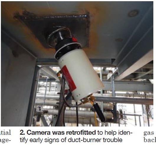
A good 21st century alternative to viewports is a set of duct-burner cameras. They may be mounted on the floor, roof, or walls of the firing duct and send a wireless signal to a DAQ device connected to the plant’s main control system. Cameras require purge air for cooling. Because the cameras are monitored from the control room, they can help identify early signs of burner trouble while avoiding the hazards and inconsistencies of frequent (or infrequent) viewport use. Fig 2 shows a recently installed duct-burner camera.
Flow control. Congdon noted that users often will be forced to repair perforated flow-distribution plates in the hot gas path, and may chose not to replace them because of the high frequency of their decay. While it may be possible to remove perforated plates without going out of emissions compliance, insidious maintenance issues can develop.
The most frequently observed problem resulting from removing perforated plates from the gas path is bad flame shape—local back-eddies are a particular issue that damages liner and burner components. Another issue associated with perforated-plate removal is excessive flam
e length in the upper portion of the duct. This can lead to non-uniform tube metal temperatures, overheating of the tubes at high elevations, and, ultimately, tube failures.
Flow-distribution plates slow down the gas velocity in the lower portion of the firing duct where turbine outlet pressure is highest. Without the perforated plates in place, the exhaust flow profile would naturally favor the lower portion of the firing duct, and higher elevations would have significantly less exhaust ga
s flow.
With reduced gas flow, mixing is diminished. The stoichiometry becomes offset, since burner elements put out uniform quantities of fuel, but the quantity of air is suppressed at higher elevations. Even though the flow velocity is lower, the flame takes much longer to consume the fuel, resulting in an extended flame length. This is often referred to as a “long lazy flame.”
Thus, it generally is not a good idea to remove perforated plates from the gas flow path. The result is often slowly forming damage to the higher portions of the tube panels, where inspections tend to be less common. Such tube damage often goes unnoticed until a full-on leak demands a forced outage. A drone inspection can aid O&M teams to pinpoint upper-level tube damage in boilers where an uneven gas flow profile is suspected.
Internal deposits. Congdon discussed several problems associated with the growth of oxides along the inside walls of superheater and reheater tubes made of steels containing chromium. In small quantities, oxides protect the tubes from corrosion. However, too much internal oxide growth, or an uneven distribution profile, can insulate sections of tubes, creating temperature imbalances that can cause creep damage and ultimately lead to failure.
Many chromium steel alloys have been used in the manufacture of superheater and reheater tubes. High-chrome alloys, such as T91, generally produce less oxide growth, but also tend to be more expensive. Many ageing boilers were fabricated with lower chromium-containing alloys, such as T11 and T22, and are highly prone to oxide growth over time. Superheater and reheater panels with high heat flux are especially vulnerable to damage from internal oxide growth, because tubes in these sections generally were not designed with a high margin for wall thickness or deviation in temperature gradients.
Internal oxide growth along a superheater or reheater tube can result in tube swelling over an extended period of time, and may eventually lead to a complete rupture. The oxide layer insulates the internal surface of the tube, adding an additional thermal resistance to the heat-transfer path between the flue gas and the steam. This causes the tube metal to reach thermal equilibrium at a higher temperature, overheating the metal.
With added thermal resistance from an excessive internal oxide layer, the operating temperature of the tube metal goes up. The tube wall then becomes slightly more plastic, and the tube slowly begins to yield to the hoop stress generated by the steam. Over time, the tube will swell as the tube metal starts to yield as creep.
Aside from reducing burner heat release, there is little that can be done to reduce internal oxide growth in low-chromium-content steel alloy tubes. Superheater and reheater tube panels with high heat flux should be inspected regularly during the latter half of the boiler’s design life.
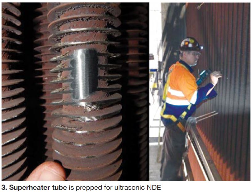
Internal oxide growth can be qualitatively assessed by borescope inspection, and can be quantitatively measured using NDE techniques. Fig 3 shows a superheater tube being prepped for an ultrasonic NDE.
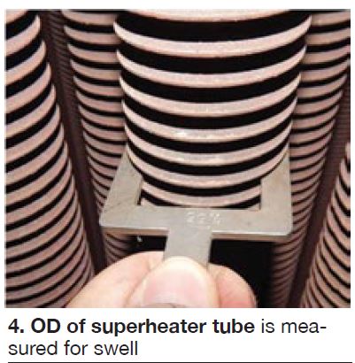
If excessive oxide growth is suspected, it’s a good idea to measure tube ODs at strategic locations to get an idea of how much swelling has taken place. Swollen tubes must be replaced; they generally cannot be saved. If the OD has swollen by 3% or more, HRST recommends derating the burner until the tubes can be replaced.
A quantitative engineering analysis is required to determine by what percentage the burners must be de-rated to preserve the lifespan of the tubes to the next available outage. It is generally good practice to be proactive in identifying and replacing swollen tubes before they rupture. Fig 4 shows a superheater tube’s OD being measured for signs of swelling.
High levels of internal oxides also can result in the liberation of oxide flakes and particulates into the steam. This can be erosive to steam turbine blading. If excessive oxide growth is suspected, consider installing a duplex strainer before the steam-turbine inlet, if there is not already one in place. This can prevent erosion damage to the first few stages of blading from liberated oxides.
Firing ducts. Congdon discussed failures of stainless-steel liner panels typical of older boiler designs. Type-309 stainless steel often was used to line firing ducts in boilers installed 15 or more years ago. Type 309 has good oxidation resistance, but tends to warp in high-temperature environments.
Many users find themselves having to repeatedly reline boiler walls around the duct burner during maintenance outages. Some users who had encountered this problem found success in retrofitting the lining with ceramic-fiber modules. While there is a high one-time cost incurred by this, it reduces the frequent need to reline the firing ducts. A cost-benefit analysis may favor this decision in the long-run, while it may also increase reliability and reduce downtime.
Steam-line creep. In ageing plants, it can be helpful to investigate the health of high- temperature steam lines with regard to creep damage. The potential for creep damage can be analyzed remotely using process modeling software to determine the most likely weak spots in the pipes. The analysis can then be assimilated into a site-specific test program to strategically focus the NDE on the most probable locations for damage.
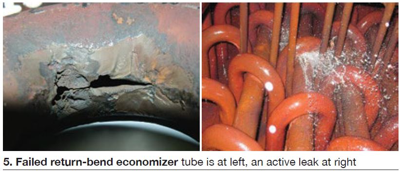
Return-bend economizers. Congdon discussed the commonly encountered failure of return-bend economizers resulting from tube-to-tube temperature differentials with a top- supported structural design. Ageing return-bend economizers often are prone to failures at the bends. Temperature differentials may develop between economizer tubes during transient startup periods, causing uneven thermal expansion of the tubes. Return-bend economizers usually are top-supported at the inside of the tube bends by a support beam.
Tubes at high temperatures will elongate and no longer support the load of the economizer. Thus, the mechanical load concentrates on the cooler tubes, causing an off-design distribution of weight. The result is a higher concentration of stress at the bends of the cooler tubes, which can lead to cyclic stress, fatigue, corrosion fatigue, and stress corrosion cracking failures. Fig 5 shows a failed return-bend economizer tube at the left, an active leak at the right.
Temperature differentials occur naturally during startup in return-bend economizers where cold water flows into the top of the top-supported header. These conditions may be exacerbated by air pockets in the bends, which are not vented easily. Operationally, maintaining a small but steady water flow through the economizer during startup can help smooth out the temperature differences.
A good long-term maintenance solution is to retrofit a support system that isn’t prone to transient differential stress loading. HRST developed a support system design for return-bend economizers that can redistribute the stresses to the bottom of the unit. Supports can be retrofitted to eliminate the support rods in favor of a bottom-supported design with spring isolators to help buffer transient deformations. This design prevents high stresses at upper tube bends, eliminating the risk of failure in those locations. CCJ