


User, vendor technical presentations, safety discussion highlight program
(Scroll to bottom of page for graphics.)
Chairman Russ Snyder, plant manager, Cleco Power LLC, called to order the first user-only technical session at the 2012 meeting of the 501F Users Group on the third day of the conference. He quickly passed the microphone to Vice Chairman Ray Martens, plant manager of the Klamath (Ore) Cogeneration Plant, who led a robust discussion on safety. The second day of the event was spent in closed session with engineers from Siemens Energy, Orlando; the first day focused on vendor presentations.
Over the last several years, personnel safety has grown in importance and today it is the top concern of executives and managers in the electric power industry. Entries received by the editors for this year’s Best Practices Awards program (coverage begins on p 19) verify the priority placed on safety today. Five years ago, entries for O&M best practices outnumbered safety entries by more than three to one. This year, there were one-third more entries for safety than there were for O&M.
The CCJ archives (www.ccj-online.com/archives) offers a wealth of ideas on the systems and equipment and procedures and administrative methods available for improving plant safety. Reading through the Best Practices entries in every 1Q issue for the last few years is sure to provide the foundation for a successful plant safety program. Several ideas presented in those issues were discussed in Tampa, plus others, of course.
Fire in the filter house.The subject of the fire risks associated with work on the air inlet house stimulated conversation for perhaps 15 minutes. Far too frequently, there’s a report of a fire caused by welding on the filter house; dry air filters and evap media ignite quickly. However, the fire described during Martens’ session was caused by a halogen lamp.
Workers hired to change filters were using a halogen lamp in the narrow passageway between the prefilters and conical/cylindrical final filters and forgot to turn off the light before quitting for the day. Exactly how the fire got started is not known; evidence was consumed in the resulting blaze. The person telling the story said the fire department was called at the first sight of smoke but the filter house was a goner in a matter of minutes.
One thought was that the door to the air inlet house, though which the power cord for the lamp passed, closed and moved the lamp in contact with filter material. The job foreman said the door had been tied open, but it was a windy day. The group discussed the incident. One attendee said running a power cord through an open door was an unsafe work practice and should not have been allowed; wall penetrations for utilities should have been installed (see pp 24 and 51).
Another recalled that at least one of the OEMs had issued a safety advisory on lighting inside filter houses that said only low-wattage lighting should be allowed. Someone else suggested the use of LED (light-emitting diode) lighting.
A productive “thread” was underway. Lighting aside, the best observation and thought for the day was that the access door to the three-story filter house was on the first floor and that was the only way to get into and out of the structure. Had a worker been at the second or third elevation (access by wall-mounted ladder) when the fire started, observers said he or she probably could not have survived. The plant is now installing access doors at each level.
Workplace cautions came at a rapid rate as Martens “worked” the room. One person mentioned the fire hazard associated with a borescope light, another talked about the danger of exploding hydraulic lines, yet another about the need for local shutoff switches at each cooling-tower fan.
The subject of roping off restricted areas brought this caution: Be sure to check enclosures within the restricted sector for personnel before marking off the area with “danger” tape. A user remembered a couple of people working in a CEMS house suddenly being trapped in an unsafe area because no one knew they were there. The acronym “CEMS” triggered another safety idea: Install an O2 sensor in the instrument house that alarms if the oxygen level drops to that needed to just sustain life. This could occur in the unlikely event of leaks from stack and calibration gas lines.
Visible and meaningful labeling was another subject addressed. One person took issue with the way some of his colleagues who had served in the navy labeled access points and components. He suggested that codes, especially those using numbers, might be fine aboard ship but recommended clear wording in shore-side powerplants. Another attendee stressed multiple languages.
Judging from a few questions related to O&M of gas piping systems, it seemed some attendees were unfamiliar with NFPA 56, the new safety standard designed to protect personnel and equipment against explosion and other hazards associated with the use of natural gas. This standard provides minimum safety requirements for the commissioning and maintenance of fuel gas piping—from the point of delivery to the equipment shutoff valve. It is the first such standard applicable to powerplants. To learn more, read NFPA 56 is a ‘game changer’.
To purge or not to purge. A comment from the floor on changes to NFPA 85 that would allow a gas-turbine restart without having to purge the HRSG, thereby saving valuable minutes, got the group buzzing. But no one in the room with in-depth knowledge of the subject stepped up to lead the discussion and no definitive guidance was offered. That was unfortunate because the recent changes to NFPA 85 seem important to deck-plates and management personnel alike.
However, the lesson re-learned in Tampa was that plant owners should never underestimate the value of user-group meetings and the “reach” they have. Two days before the 501F users met in closed session there was a presentation by Frank Berte, a member of the management team at Tetra Engineering Group Inc (US office in Weatogue, Ct), covering changes to NFPA 85. During the safety session, the thread on NFPA 85 probably was started by an attendee reaching out for clarification of something he heard from Berte or indirectly from someone who sat in on Berte’s session.
But there’s more to this story: A plant engineer who was in Tampa and obviously looking for more information on the subject asked, the day after the meeting ended, the following question of participants in the Heat Recovery Steam Generator-HRSG discussion group on Linked-In.com, which just happens to be managed by Peter Jackson of Tetra Engineering: “Anyone scheduled to implement new NFPA rule to avoid HRSG purge on CTG restart?
“I just heard there is a newly published NFPA rule that would permit skipping the mandatory HRSG purge during CTG restart provided (a) methane monitors are installed in the upper HRSG gas space and (b) a triple block-and-bleed [arrangement is] installed in the fuel gas line to the combustors (CTG and duct burner). Skipping this purge on hot restart would avoid forming condensate in the superheaters and reduce damage at the tube-to-header welds, and also shorten the hot restart time. Can anyone advise the new NFPA reference paragraph and advise if they are scheduled to implement the upgrades to allow its use?”
Jackson replied with the content of an informational mailing made at the end of 2011 by Tetra Engineering to its clients and prospects. Here key elements of that material:
- Purge credits. There has been a significant code change affecting startup purge requirements for combined-cycle powerplants. The 2011 edition of NFPA 85, “Boiler and Combustion Systems Hazards Code,” now allows operators to credit prior purges if they have implemented positive gas-flow cutoffs and monitoring systems. Purge credits can be maintained for an eight-day period and extended by implementing a purge.
- Who benefits? This will benefit cycling units by allowing them to eliminate purges for many hot and warm starts, thereby (a) resulting in faster startups (improvements of 5 to 15 min), (b) eliminating purge cooling and condensate quenching on superheaters and reheaters, and (c) reducing purge power requirements.
- How to implement. Implementing the purge credit requires minor modifications to gas-turbine and duct-burner fuel lines (additional valving and instrumentation), interconnection with monitoring systems to provide surveillance and annunciation, and procedures to cover the new purge credit requirements.
The plant engineer who initiated this thread did some follow-up research and later provided the online group the following details regarding implementation:
- NFPA 85 (2011), paragraph 8.8.4.6. Triple block and double vent valves on gas turbine and duct-burner fuel lines. Valve positions shall be continuously monitored. Pressures in the block-valve sections shall be continuously monitored. Valves to be validated for leak tightness prior to each startup and following each shutdown.
- Paragraph 4.10.3 provides guidance on a positive means to prevent leakage of ammonia.
- Methane monitors. The plant engineer found no explicit statement on methane monitors but believes they are wise to include.
More on purge credits. A quick call to Amy Sieben, Lester Stanley, and Scott Wambeke of HRST Inc, Eden Prairie, Minn, contributed additional insights for users to consider before making decisions on when to purge. Quick startups are valuable for dispatch sake, the trio acknowledged, but there still should be careful evaluation of the HRSG system to help avoid cycling problems.
Spending money on hardware and controls to achieve a startup purge credit during shutdown doesn’t minimize the need to evaluate and install properly sized, located, and controlled superheater and reheater drains, they said. In addition, each HRSG site should evaluate and determine the minimum purge time that meets NFPA requirements. This is important because a trip/restart will still require a purge.
An overnight shutdown will mean a purge during shutdown to achieve the credit, and this purge will still cause condensate to rain down on hot headers. It only takes one bad startup with water trapped in lower headers to cause damage. Sometimes a purge during shutdown can create more condensate in superheaters than a purge during startup—especially if the startup is after HP system pressure has had an opportunity to decrease.
For the shutdown purge, boiler pressure generally is at near full operating pressure. If your current purge is longer than 10 minutes, the three engineers said, a qualified consultant can analyze and often provide a more precise and shorter purge time that still meets NFPA requirements. They concluded the interview essentially with their opening thought: A thorough HRSG cycling study can help sort out your options.
Interestingly, Brian F Craig, PE, of HRST spoke to that subject at the vendor forum early in the week. His thoughts are summarized later in this report.
Formal user presentation
The first of 10 user presenters discussed efforts taken at his plant to minimize offline corrosion. The 2 x 1 501FD2-powered combined cycle is located in a humid area and can be offline for extended periods. A three-pronged approach was implemented. Moving from the air inlet to the stack, here’s what was done: Dehumidifiers of the desiccant rotor type were installed in the inlet plenums of both gas turbines; a waterside heater was installed in each heat-recovery steam generator; dampers were installed on both stacks to stop, to the extent possible, the flow of air through the HRSGs.
The skid-mounted waterside heaters are each rated 4 million Btu/hr. They circulate warm water through a few panels (harps), which then act as radiators to maintain the relative humidity below 30%. The HRSG waterside is protected by a nitrogen blanket. When steam pressure decays below 50 psig following a unit shutdown, nitrogen is introduced automatically. Another enhancement installed removes air from lube oil flowing to the torque converter to protect that component from corrosion.
Leaning stack. Stacks with dampers often are insulated to prevent heat loss through the wall of the vertical cylinder. The first speaker didn’t mention stack insulation as a deterrent for offline corrosion but the second speaker showed how important periodic inspection is if you do. An operator making rounds at the 250-MW 1 x 1 LSP-Whitewater LP facility noticed rust stains on the stack and observed excessive movement of the chimney during a wind storm.
Closer inspection after removing insulation from around the ring supports of the insulated stack revealed significant corrosion at the damper level that had completely penetrated the metal in some spots (photo). A civil survey revealed that the stack was 10 deg out of plumb, more than twice the lean of the famous Tower of Pisa.
Root cause of the damage was localized corrosion under the exterior insulation. Water collecting around the support penetrations was being trapped under the insulation, which was behaving like a sponge. Poor QA/AC during construction was another factor. Holes were in place for drain piping, but it was not installed. Get the full story by accessing “Don’t ignore your stack” by Plant Manager Todd Kutz at http://www.naes.com/literature-articles.
Sinking feeling. Next, a plant manager took the podium to report on aft bearing sag—130 mils worth. The 501F engine had about 38,000 hours and 1800 starts under its belt when serious damage occurred. Exhaust-section sag was said to have started slowly, which is common; the OEM attributed that to creep. But the sudden drop in rotor position that occurred next was not typical.
All compressor diaphragms had to be replaced, along with 200 compressor blades and Rows 3 and 4 in the turbine section. There were no cracked struts, but there were cracks in strut shields. The speaker reported plant personnel remembered hearing a helicopter-like sound on startup. Vibration had not been an issue.
The dead-air-space baffle is designed to keep exhaust flow from reaching the outer shell of the exhaust section. The OEM currently is on design revision III, which was made necessary by failures of segments designed to Rev II, a user reported. Rev III reportedly is working well; future revisions probably will involve materials upgrades. One challenge is that baffle material must be machined to fit the slot provided because mills do not offer the thickness required.
Calling Sherlock Holmes. The next speaker told of a 501FD2 forced out of service last summer after 41,000 equivalent hours and 2570 equivalent starts when a disc cavity 4 (DC 4) temperature drop of 80 deg F was confirmed by both thermocouples in that space on two consecutive starts. Temperatures in the other disc cavities were normal. A review of data captured by the historian revealed low DC 4 temperatures in the previous seven runs; however, they were not as low as those identified with the latest two runs.
DC 4 temperature was acceptable on the ensuing start. This came as a surprise and led engineers to consider that the anomaly might not be associated with the bellyband as originally thought. Plant personnel checked for instrumentation error, thermocouple damage, and bellyband failure before opening the unit, which had been opened only three months earlier to replace R2 blades. The bellybands had been replaced in 2008.
Inspection results were positive. The condition of the interstage air seal was good, with minimal mushrooming. Seal segments were properly installed and were not free to move. Bellybands were in good shape with the exception of an indication on the R4 bellyband; this was replaced as a precaution.
Another mystery then surfaced. Personnel began rolling the rotor to gain access to the bellyband and stopped when they heard a loud screech. A nut from the balance access tube cover was found trapped in the static-seal area. Personnel tried to roll the rotor again with the same result. Extensive inspections did not reveal the cause of the noise, which then disappeared. DC 4 temperature was normal following the outage. But a few weeks later, indications of a DC 4 temperature drop was recorded by one of the thermocouples. A root cause analysis provided no answer. If you have any ideas, write the editors—scott@ccj-online.com.
Where have the static seals gone? Three 501FD2 gas turbines had their R1 turbine blades upgraded during hot gas path (HGP) inspections as part of the OEM’s Value Generation Program. VGP blades were characterized by short seal pins. About nine months and 220 equivalent starts following the HGP on the first unit, the unit was removed from service to change-out R2 blades.
Inspection revealed damage to R2 blades and vanes. The combustor was opened; no findings there. Then the cover over R1 blades and vanes was removed and revealed four missing static seals and heavy damage to a fir tree in the R1 disc. Recall that static seals, located inside the R1 vanes, form the seal between the HGP and DC 1 (disc cavity) by way of close clearance with the angel wings on R1 blades.
Cooling is provided from leakage along the torque tube labyrinth seals (the torque tube is that portion of the rotor between the compressor and turbine sections). Important to note is that the additional cooling required for the VGP R1 blades reduces the pressure in this area and permits the ingestion of hot gas into DC 1.
Plant personnel said there were no compelling signs of a problem prior to the outage. Review of archived data revealed two small step changes in vibration the month before the unit was removed from service, but they were not noticed by operators and were well below alarm limits. Investigators found that the reduced level of cooling was conducive to overheating of bolts holding the static seals in position. Some bolts failed, allowing seals to liberate. This was communicated to the fleet by the OEM after the investigative work was complete.
Decisions were needed on how to remediate the R1 fir-tree damage and how to increase the flow of cooling air. Options for repairing the fir tree were the following:
- Machine in-situ. This had not been done previously and was considered a high-risk solution.
- Remove rotor and machine. The normal risks regarding rotor removal and de-stack prevailed.
- De-stack rotor and replace R1 disc. Turnaround time is significant for this option.
- Exchange with refurbished rotor. A costly alternative but the one offering least schedule impact (assuming the unknowns associated with in-situ repair would have schedule impacts).
The owner chose to exchange the engine’s rotor with a refurbished one. The total outage took 60 days. Static seals of the original design were installed and the old-style long seal pins used on the R1 blades.
Inspections were arranged for the remaining two engines as soon as work was completed on the first one. The second and third 501FD2s underwent their HGP overhauls five months after the first unit, so they had less in-service time with the VGP R1 blades at the time they were inspected than their sister machine had. No major problems on these units. An axially displaced static seal and two missing bolts were found on one engine; signs of overheating were in evidence on the other but all bolts were in-place.
Static seals were replaced on both units via the combustor. Replacement seal for one engine was of the original design with holey bolts (bolts with holes drilled through the center to provide a passage for cooling air) of stainless steel. The remaining machine featured a newly designed static seal together with the original holey bolts of stainless steel. The new Hastelloy static seal and honeycomb are engineered to reduce warping and loss of cooling air in DC 1.
End notes: After work on the second and third gas turbines was completed, the first unit was removed from service again, after 190 equivalent starts since the seal repair. The static seal had signs of minor warping, but no overheating. Recall that the longer R1 seal pins were installed six months earlier during the last outage. The Hastelloy static seal was installed using the new Inconel holey bolts.
Other presentations included one on exhaust cylinder crack repairs and another on spark-erosion remediation. The first plant reported that no weld repairs to the exhaust cylinder had worked, despite repeated attempts. The speaker noted that the stress on the front end of the exhaust cylinder was nearly three and a half times that at the back. Plant management decided to evaluate the service effectiveness of an overlay applied with robotic welders offered by Atlanta-based Aquilex. It took eight days (two 12-hr shifts per day) to apply the overlay, which was said to have reduced stress by 22%.
VENDOR PRESENTATIONS
Owner/operators attending the annual meeting of the 501F Users Group who did not attend one of the five presentations offered in each of the 10 sessions that comprised the 2012 Vendorama program passed on a valuable learning experience. Vendorama is the name used to describe the lineup of vendor presentations that supplement the user exchange at this annual conference.
The steering committee expended significant effort to ensure that the 50 presentations would be technical in nature and not the sales pitch attendees would likely get in the exhibition hall. Not every presentation was worthy of an “A” grade, of course. But there were many of significant commercial value to users. Here are summaries of several presentations selected by the editors for expanded coverage.
HRSG assessment recommended for units in cycling service
Nearly all HRSG components wear at a faster rate in cyclic operation than they do in base-load service. To assure a given unit will meet the owner’s expectations regarding service reliability and lifetime, Bryan F Craig, PE, of HRST Inc, Eden Prairie, Minn, recommended an engineering assessment of design details and operating practices for units already cycling as well as those expected to cycle in the future. Such a review would enable owners to correct potential weaknesses and initiate corrective action before more, or perhaps any, damage is done. It would also identify risk areas to monitor in the future.
Perhaps the most valuable take-away from Craig’s presentation was a checklist of concerns that HRSG believes should be included as part of a cycling study. Criteria for inclusion in the checklist presented below, which is not complete, were the following:
- The most common concerns and ones that can cause the most significant operational and/or reliability problems.
- Issues that are not specific to one manufacturer of heat-recovery steam generators.
Within the time constraints of the session, Craig explained how to identify some of the high-profile concerns and offered guidance on how to address problems identified.
The boiler expert began his presentation with a few remarks on low-cycle fatigue. He said that many cycling-related HRSG failures are attributed to LCF, fatigue caused by repeated yielding (plastic deformation) of boiler materials. Most attendees sat straight-up when Craig said, “LCF failures often occur in fewer than 1000 stress cycles.” No one needed a calculator to figure out that meant HRSGs starting daily might be forced out of service for major repairs in less than five years of service.
Craig’s checklist of most common concerns follows:
Superheater/reheater design and arrangement
- Desuperheater overspray, hunting
- HP superheater/reheater thermal stress
- HP superheater/reheater drains
- Cold-reheat condensate drains
- Proper operation of spring supports
Economizer arrangement
- Tube thermal stress at startup
- Vents and drains
Evaporator/steam drum design
- Drum nozzle cracking
- Belly pan cracking
- Drum swell
Casing/gas-side concerns
- Perforated plate and/or turning vanes with sections of varying thickness
- Damage to breech expansion joint
- Damage to pipe seals
- Casing cracks
- Damage to burner elements caused by condensate
Layup
- Evaluation of practices and procedures
- Internal corrosion from oxygen ingress, FAC
- External corrosion
- Stack damper/insulation
- Freeze protection
How ACT repairs R1 turbine blades
R1 turbine blade repairs are a continuing topic of discussion at meetings of the 501F Users Group. Matthew Lau, VP of operations for ACT Independent Turbo Services, Houston, presented at this year’s meeting on “R1 repair fundamentals and applications.”
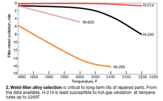
He began by reviewing some of the common failure mechanisms for R1, with a focus on blade tips and platforms (Fig 1). Lau explained that oxidation reduction/avoidance is important in both failure areas, and weld-filler alloy selection (Fig 2), improved cooling schemes, and advanced coatings are the best tools in a repair facility’s arsenal to achieve this goal.
The repair expert defined the chemistry and properties of the blade base material (738LC) and repair-alloy candidates. ACT uses Alloy-214 to address platform cracking issues, Alloy-230 for tip welding, and Alloy-230 for most tip-plate replacements. He mentioned that an alternative nickel/cobalt tip-plate alloy sometimes is selected for engines in peaking service.
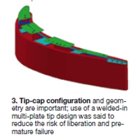
Lau reiterated that although properties like ultimate tensile, yield strength, toughness, and creep resistance are important, oxidation resistance is paramount for weld-filler alloy selection at the blade tip, where stresses are relatively low. Tip-cap configuration and geometry also are important and converting tips to a welded-in multi-plate design reduces the risk of blade-tip liberation (Fig 3).
On blades with severely distressed platforms, ACT uses a patent-pending process that incorporates an engineered sintered preform made of Alloy-214. Lau said that the preform’s properties are engineered with high uniformity, oxidation resistance, and low porosity. The process removes the distressed area via machining until all cracks and oxidation-affected areas are eliminated. Deep cracks are “surgically” removed and welded prior to continuing the platform restoration process.
After a proprietary cleaning process, ACT restores the area with the sintered preform and Capillary Action Bonding (CAB) process in a vacuum furnace. The final step in platform restoration includes machining of the platform geometry and the addition of cooling holes.
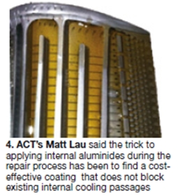
Although the coating systems are an integral part of advanced-technology blades, Lau noted that diffused internal aluminides often are overlooked despite being critical to protecting newly deposited repair welds and cooling holes (Fig 4). The trick to applying internal aluminides during the repair process, he said, has been to find a cost-effective coating that does not block existing internal cooling passages.
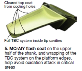
Lau continued, next describing an F-class strain-tolerant coating with high-density, microstructural features for enhanced thermal-shock resistance and porosity levels conducive to low thermal conductivity. He explained that having an excellent TBC system is not enough and that application and tolerances make the difference. Lau added that coating inside the tip cavities, applying MCrAlY flash coat on the upper half of the shank, and wrapping the TBC system on the platform edges help avoid oxidation attack in critical areas (Fig 5).
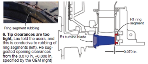
Lau ended his presenation with a discussion of blade tip heights and clearances. The design clearance is too tight, he believes, and should be increased by as much as 40% (Fig 6). Lau added that a repair shop should never decrease the spec tip clearance; he also advised attendees to consider dimensional distortion and coating clearances during the restoration of R1 ring segments.
Lau’s concluding comment to the users was that several of the mods discussed could be applied to new or pre-engine-run blades. If applied correctly, these applications can improve the repairability and overall life of the blades, thereby significantly reducing costly fall-outs.
Mitsubishi promotes upgrades for 501F rotors
Scott Cloyd, director of gas turbine engineering for Mitsubishi Power Systems Americas, presented on the following of his company’s upgrades for 501F rotors:
Belly bands(or baffle plates if you prefer) seal against air leaks between turbine rotor disks. You don’t have to attend many 501F meetings to realize belly-band issues strike a nerve in many users. Cloyd suggested that users consider replacing their original belly band with Mitsubishi’s two-layer baffle plate and bolted locking piece as several users already have done. He said this mod could be made any time the turbine casing is lifted. Some machining is involved, he added, because the existing slot must be enlarged. A benefit of the design was said to be easy removal when leaks occur.
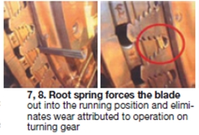
Blade root springs. Disk serration wear caused by long-term operation on turning gear now can be mitigated with a patented blade root spring that is slipped between the wheel and the bottom serration of the blade (Figs 7, 8). The spring forces the blade out into the running position and eliminates turning-gear wear. It also tightens the vibration profile of the machine making vibration more repeatable from start to start. At the present time, the spring is only designed for R4. A typical row can be equipped with springs during a 48-hr outage. Access is via the exhaust duct with removal of the locking plates. A cover lift is not required.
Bolted air separator is designed to replace goose-neck air separators still in use on FC and FD machines. In the latter, the seal of the air separator to the R1 turbine disk is provided by the spring force of the goose neck against the air separator. The force at this point is critical to the rotor:
- Too low a force leads to fretting at the disk interface.
- Too much force reduces the preload at the spacer disk and increases wear at the curvic coupling.
- Startup and shutdown thermal transients adversely impacts the preload and results in high rotor vibrations.
Cloyd said the bolted air separator decouples the seal portions of the device from the rotor core. New components required are the air separator, seal ring, dummy rings, and bolts. Modifications are required to the torque-tube seal housing and R1 turbine disk. The retrofit requires de-stacking of the rotor and makes most sense to conduct during a comprehensive rotor inspection.
For history buffs, the bolted air separator has been used in Mitsubishi gas turbines since 1996. Siemens stayed with the original air-separator design developed by Westinghouse and Mitsubishi when the latter went to the bolted design.
Beyond the engine: PSM pursues exhaust-case solutions
Many experienced 501F owner/operators have been following the development of PSM’s product line for several years and they knew many of the things Manager of Airfoils Engineering Chris Williams spoke about during his presentation. But most were hearing about the company’s move into exhaust-case solutions for the first time.
Williams began with the company’s compressor solutions, which were divided into the following groups:
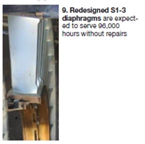
- The S1-3 diaphragms, installed without case modification, are designed to run 96,000 hours without repairs (Fig 9). The first set installed was heavily instrumented and operated without restriction on a standard IGV schedule. The speaker said everything worked as predicted: airfoil strain below design limits, accelerometer response minimal at all IGV settings, and no measureable wear on indicators (buttons). Today, six sets of these diaphragms are in service with nearly 25,000 total accumulated hours of service. The fleet leader is north of 12,000 hours.
- S4-8 501FD diaphragms also are designed for 96,000 hours without repairs. They will be available for commercial application later this year. Features: forged and machined singlet airfoils and ID/OD rings, 180-deg bolted ID seal box with split-line jumper, no welds or case modifications, ID honeycomb improves performance.
- S9-16 design improvements include ID honeycomb for better sealing, coated hook contact surfaces, and replacement of the belly band with full-penetration welds. The last is based on the company’s success with 7FA S17/EGV assemblies. These diaphragms also will be available for commercial application later this year.
Combustors.Williams said PSM has studied all of the field issues and is offering a drop-in 501F combustor designed for a 24,000-hr/900-start interval. Operating experience to date extends beyond 14,000 hours/400 starts. A substantial reduction in NOx and lower CO emissions compared to OEM hardware was promised.
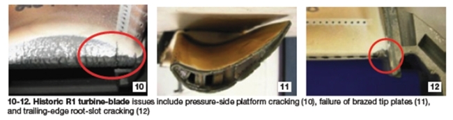
R1 turbine blades. Next, the airfoil engineer reviewed the historic fleet issues with R1 turbine blades—such as suction-side platform cracking, trailing-edge root slot cracking, etc (Figs 10-12)—and showed by way of detailed graphics the design enhancements incorporated by PSM to address known field distress. These include the following:
- Dense vertically cracked coating to increase tolerance to coating spallation and cracking.
- Through-platform pressure-side cooling holes to reduce thermal strain and stress.
- Undercut leading edge and extended axial seal slot reduce platform stresses and thermal strain.
- Larger under-platform dirt pocket to prevent pin lock-up.
The company has 33 sets of R1 blades in service today; the first began operating in 2008. Duty cycles include base load, peaking, and mixed duty. Several sets have logged more than 15,000 hours/500 starts without pressure-side platform distress and with minimal suction-side distress.
R2 turbine blades, a major topic of discussion at last year’s meeting, have been in service since February 2011; 13 sets are now operational. Prediction is a three-interval lifetime.
Exhaust design improvements. Williams said PSM engineers understand the exhaust failure modes that the fleet is experiencing—such as strut over temperature and baffle-plate and teardrop issues. The company’s new R4 blade is said to optimize strut-shield and teardrop gas flow. The introduction of exhaust-end components is planned for the end of 2013.
How to solve brush and brush holder problems
Cutsforth Inc’s Mike Biroschak conducted a short clinic on common brush and brush holder problems and how to deal with them. He closed out his presentation with a solution for bearing wear and tear caused by ineffective shaft grounding systems.
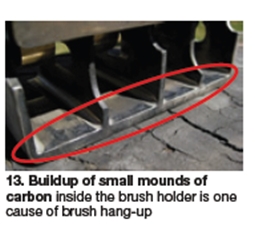
Biroschak began by saying that the buildup of carbon deposits in brush holders is the primary cause of collector-ring fires. The buildup of small mounds of carbon inside the brush holder is one cause of brush hang-up (Fig 13). Carbon particles are produced by the repetitive impacting of the brush against the holder wall. Such buildup is difficult for maintenance personnel to see but it can be identified from marks made in the side of the brush.
Brush binding is another cause of holder-related restriction. It is caused by the brush dragging against the side of the holder. Angular pressure increases the likelihood that the brush will become stuck in its holder. Where the brush box is shorter than the brush it holds, a ledge can develop in the brush and cause it to hang up.
Worn, damaged, or broken springs lose some or all of their tension and cause brush wear and out-of-round rings. Too much spring tension can increase brush wear but not mechanical wear of the ring. Biroschak pointed out that most springs are attached to the back plate of the brush holder and cannot be changed without a shutdown. That is not the case with the Cutsforth solution.
Sulzer’s Romero talks rotor repair to 501F users
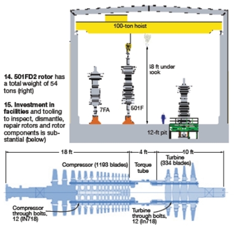
Sulzer Turbo Services’ Engineering Advisor Fernando Romero offered an instructive look at the dismantling of a 501FD2 rotor, inspection of its component parts, appropriate rotor repair methods, and reassembly (Fig 14, 15). He said Sulzer had done work on a dozen such rotors, dismantled six, and found failed components on two of the six. To learn more about rotor disassembly, read “Recovering from a wreck,” which appeared in the 4Q/2009 issue of the CCJ
The first case history Romero discussed was a rotor that had been removed from operation because of high vibration resulting from a turbine blade failure. The aft end of the third turbine stage had high run-out and a 360-deg, 1-in.-deep crack was found at the third-stage pilot. Fracture surfaces showed evidence of heating, rubbing, and beach marks indicative of fatigue. Corrosion pits were easy to see on the OD of the rabbet fit under an optical microscope. A scanning electron microscope revealed corrosion pits at the crack initiation sites.
The rotor showed no signs of intrinsic material defects that could have contributed to this failure. However, corrosion pitting was linked to the dozens of initiation sites found at the OD of the part. An insert was designed to take the place of the pilot, which is only used for assembling the machine. The design was qualified by using finite element analysis.
Second case history. The rotor, taken out of service because of a lube-oil-system failure, did not exhibit abnormal vibration or run-outs. However, both the compressor and turbine shaft ends suffered heavy rubs. Plus, the pilot had failed and was hanging from the fourth-stage disc. Additionally, the compressor shaft end had deep rubs in the oil seal area and the probe targets were out of tolerance. Shaft surfaces were repaired by submerged arc welding, then the shaft was stress-relieved and finish-machined.
Allied Power’s R1 turbine-blade repairs, mods reduce scrap rates, extend part life
The repair expert began his presentation with an examination of the OEM’s “old” R1 blade, made of equiaxed Inconel 738 and equipped with an “ineffective” cooling slot. Industry experience is that you can expect severe platform oxidation with this 14-yr-old design. Several photos were offered as proof.
Historical data from 2008, Frost continued, indicate that you can expect to lose one-third of the R1 blades in base-load units after 12,000 to 16,000 EOH. Engines not operating in base-load service can suffer nearly 100% scrap. APG’s work shows that for this blade design, platform cracks occur very quickly in life for starts-based machines. Specifically, Inconel 738 can crack in only 140 starts.
Examination of braze repairs by the OEM showed them to be generally ineffective. Braze consistency is difficult to control, Frost said, and sometimes it doesn’t fill the crack as it might appear. High porosity is another problem encountered.
A third-party supplier of new R1 blades has had some success by rounding platform edges to reduce cracking potential, he added. Also, the cracks are not propagating quite as long because of this design improvement. For these blades, a deep-crack platform weld repair can be effective. Crack removal and fluorescent penetrant verification are the first steps. Weld repair comes next, followed by heat treatment and full fluorescent penetrant examination. A couple of cut-ups for metallographic examination are recommended.
For an OEM set, all burned and weakened base material at the platform edge must be removed before weld repairs. Photos illustrated these points as well. Allied’s welding is done with an alloy weaker than Inconel 738 but one significantly better than 625, the usual choice. That’s as much information as Frost was willing to share. After the platform is fully welded, the front face is remachined to assure proper seal-pin fit, APG’s platform cooling mod is installed, and another mod implemented to prevent buildup of problematic foreign material behind the seal pin.
New tip-cap welding and reconstruction procedures follow. Allied uses Haynes 230 material for its tip cap. First step in the process is to remove old tip caps and cooling holes, then pre-cap weld, tack weld the new tip cap, complete the tip-cap weld, and add the squeeler tip. Finally, the cooling holes are replaced, completing the repair. Each piece then is checked by CAT scan x-ray. Final step in the rehab process is the application of dense, vertically cracked TBC.