


Impossible to pack more knowledge into four days
| 1. CTOTF’s top vendor supporters for 2013
Super Champions Allied Power Group LLC Champions AAF International |
Setting the stage for CTOTF’s 38th annual Spring Turbine Users Conference and Trade Show, April 7-11 in Myrtle Beach, SC, a confident Bob Kirn of TVA, the group’s chairman, told the editors “the role of natural gas in electricity generation will continue to expand as nuclear languishes under extraordinary costs, coal remains the environmental villain, and the proven reserves of natural gas continue to increase.”
 He added that after factoring in high-cost renewables of questionable reliability, the complexities of grid operation in an era of must-take intermittent resources, looming CO2 emissions limits, increased regulation, and today’s dramatic load profiles, gas turbines and their owner/ operators find themselves center stage, required to provide and sustain ever higher standards of performance.
CTOTF’s meetings and digital resources have evolved with the changing information needs of users. Subject matter incorporated into the group’s semiannual conferences goes well beyond the gas-turbine enclosure. All equipment and systems required by simple-cycle, cogeneration, and combined-cycle plants powered by GTs are covered, and related industry, management, and regulatory topics addressed. On the equipment side this includes everything from the air inlet house to the high-voltage connection to the grid.
Attendance at the meeting in Myrtle Beach, Kirn assured, will bring you up to date on methods and technologies for improving performance, reducing emissions, and stretching the O&M budget, as well as alerting you to emerging issues that require attention.
Achieving better plant performance at lower cost is an elusive goal, he said, one that depends significantly on the availability of high-quality technical expertise. However, with the trend to flatter and leaner organizations, the in-house availability of expertise to support increasingly diverse technical needs has steadily diminished.
This is where CTOTF provides a huge value-add, Kirn continued. “We serve as your ‘extended technical services department’.” Heart of the four-day spring meeting is a dozen interactive user-only sessions totaling 64 hours of presentation and discussion time—plus these special events under the CTOTF umbrella:
-
Presentation on Monday, April 8, of the 2013 Best Practices Awards recognizing the valuable contributions made by plant staffs—and headquarters personnel—in improving the performance of generating facilities powered by gas turbines. Attendance gives first industry access to this information. Implementing at your plant just one or two ideas from this year’s record number of entries is sure to pay a 10-fold return on registration/travel/hotel expenses. Note no mention of food: Wickey Elmo, president, Goose Creek Systems Inc, Indian Trail, NC, which manages CTOTF activities, provides all meals.
-
A trade show involving nearly six dozen companies providing equipment and services to generating stations will be held Monday, April 8, from 5 pm to 9. Dinner included. Exhibitors include the CTOTF Super Champions and Champions identified in Sidebar 1.
-
CT-Tech™, an additional training opportunity offered by CTOTF, this spring provides expanded instruction on fabric expansion joints, Wednesday evening (April 10) from 5:15 until 8. Dinner included. EagleBurgmann’s Mike Green will cover the following topics, among others: structure and function, selection of materials, inspection of joints, advantages of fabric over alternatives.
Visit www.ctotf.org for program details, including abstracts of presentations and biographies of guest speakers, registration information, and direct access to the conference hotel.
A robust website is critical to the success of every user group. Relatively few owner/operators can get to meetings on a regular basis, many being tied to their respective facilities because staffing is thin and there’s no backup of personnel resources. The CTOTF Leadership Committee understands this reality and reaches out to virtually all GT users via www.ctotf.org. Recall that this organization directly serves owner/operators of Siemens, Mitsubishi, Pratt & Whitney, Alstom, Solar, and GE engines—both aeros and frames.
| 2. How to access CTOTF presentations
CTOTF has added the available presentations from its recent Fall Turbine Forum to the user group’s library at www.ctotf.org, which is arranged in chronological order by meeting (most recent first). If you don’t already have a “library card” and you are a gas-turbine owner or operator, click on the “CTOTF IBBCS” button on the left-hand toolbar on the home page. Then complete and submit the online sign-up form. Confirmation of your acceptance as a CTOTF member with full IBBCS (Internet Bulletin Board Communications Service) privileges generally will be e-mailed to you within 72 hours. As a member, return to www.ctotf.org and click once again on the “CTOTF IBBCS” button and proceed to the IBBCS Website. Next, scroll down the page to “Presentation Library” and click on that link. |
The CTOTF organization chart offers a capsule summary of subject matter addressed by the group, as well as the industry experts responsible for coverage of those areas. Access the org chart at ctotf.org and click on the person’s name for an abbreviated professional resume. Have a question regarding upcoming content, an idea for a presentation, etc? Use the handy email feature.
The group’s bulletin board was created by Michael Elmo of Goose Creek Systems, who has extensive experience in the development and implementation of computer-based information systems— including nearly two decades of service with EPRI.
What sets CTOTF’s bulletin board apart from most others hosted by the model-specific user groups is that access is available free to employees of any company with an equity interest in, or currently operating, any type of gas turbine. Register today, Kirn urged, and join the nearly 1000 owner/ operators already participating in the CTOTF forum and also gain access to the organization’s library of more than 400 presentations from past meetings (Sidebar 2).
Industry issues
The Industry Issues Roundtable provided an adrenaline rush that launched the 2012 Fall Turbine Users Conference and Trade Show (San Diego, September 16-20) in high gear. The opening panel, which explored the challenges electric generators faced in meeting the needs of ISOs, ignited a vibrant exchange that suggested the nation’s grid operators may have unrealistic expectations in terms of implementation schedules for their initiatives and the associated costs.
Ozzie Lomax, manager of gas turbine and renewable generation for AmerenMissouri, chaired the panel of subject-matter experts who collectively had nearly a century and a half of industry experience. The participants were:
-
David Timson, account manager, CalISO Customer Service and Stakeholder Affairs.
-
Eddie Mims, VP of O&M, Colectric Partners Inc.
-
Bruce Rising, strategic business manager, Siemens Energy Inc.
-
Donald Schubert, senior VP, Marsh Energy Practice.
Timson’s opening remarks, tightly scripted, reflected California’s challenging energy-supply and environmental statutes which many in the room believed unrealistic. The CalISO’s mission is to ensure the reliability of the state’s electric system, no easy task. It needs flexible capacity resources—fast start, load following, standby generation, etc—to accommodate the state’s mandate of 33% renewables generation by 2020. Regarding existing generation that does not meet the ISO’s goals, the attitude is “retrofit, repower, or retire.”
 Timson didn’t flinch when asked if the San Onofre Nuclear Generating Station would return to service. He said almost casually that the ISO was planning to meeting 2013 summer requirements without SONGS. Converting the units at Huntington Beach to synchronous condensers would help the system get by without the nuclear plant.
In answering a second question, Timson said he didn’t think that gas turbines installed in the last 10 years would have a problem meeting the grid’s flexible capacity requirements. He also didn’t see California’s law eliminating once-through cooling at ocean sites as an impediment to the grid’s objectives. Timson added that another of CalISO’s objectives is to compensate generators fairly. A few attendees having experience with ISOs in other parts of the country chuckled.
Rising mentioned that fast-start engines were developed before renewables integration achieved headline status. He said that the OEMs were sensitive to the need for generators to get units into service with minimum emissions and fast starts were critical to that goal.
Rising also shared the following: The highest power bills in the US are in areas with greatest renewables penetration. Further, the average electric bill has increased every year—even with lower gas prices—except for 2009. Attendees with grey hair recalled that for decades the price of electricity decreased year over year, low-cost electricity being the driver for this nation’s economic success.
Mims, who has been around gas turbines for most of his four decades in the industry, spoke about the success of a fast-start/fast-ramp (30 MW/min) conversion project in 2009 at one of the 2 × 1 F-class combined cycles in his company’s portfolio.
This plant was making over 300 starts on an annual basis when the successful upgrade was implemented and Mims reported that there have been no adverse effects. Regular borescope inspections attest to good equipment condition, he said. The combined cycle can drop to 50% load at night while maintaining emissions compliance.
Plan is to upgrade the company’s dual-fuel 7FA peakers to fast start as well. This upgrade can be completed during a hot-gas-path inspection but will require eliminating oil capability.
Insurers, however, generally are not enamored of fast starts when they involve “older” combined-cycle plants. “Old” in the insurers’ lexicon, Schubert told the group, is five or six years. This means upgrades would be required by all plants built during the “bubble” to gain favor with insurers. Perhaps the CalISO did not talk to the insurance community before formulating its opinion of what’s realistic and what’s not.
Money is not the only consideration here. You may have to convince the insurance company that the upgrades you’re planning actually will deliver on their promise. Perhaps as many as one-third of the equipment rerates, according to insurance industry statistics, do not meet expectations; in some cases, they have caused failures that insurers have been asked to pay for. And pay insurers have—reportedly $1.12 for every premium dollar received.
Insurers also are not comfortable with combined cycles “chasing” wind, Schubert said. They have concerns about grid stability and its impact on generation—particularly where grid infrastructure is old. Expect your insurer to add restrictive language at the next policy renewal if renewables integration is part of your operating profile.
Other important points made by Schubert were these:
-
The desire for business interruption insurance can open Pandora’s Box for an evaluation of regulatory, grid, and other issues.
-
Three carriers have reinstituted fuel-quality clauses in their policies. This means that if problems with fuel quality cause damage to your equipment, you’re not covered.
-
T&D coverage is very difficult to obtain; virtually impossible if you don’t own the infrastructure. Equipment age and condition are the main reasons for the negative view.
-
Transformer losses continue to mount, particularly for units rated 400 MVA and above.
Insurers favor machines equipped with condition- and performance-based monitoring systems. Plants with staffs backed up by expertise at an M&D center get high marks from insurers.
To hold insurance costs in check, owners may have to raise their deductibles—that is, assume more risk in case of an accident. Mims didn’t see this as a problem for companies with highly experienced asset-management personnel. Tight control of repairs is critical, he said. Track and examine all parts with a fine eye.
One measure of repair quality is fallout. As an example, Mims said, you might have a goal of 3% fallout or less on the first repair, 5% maximum on the second, and 10% max on the third for a well-operated and –maintained peaker. The percentages would be higher for gas turbines serving a base-load combined cycle because average operating temperatures are higher than they are for peaking units.
Since California was the regional focal point of the discussion, the panel could not be discharged at the coffee break without mention of how emissions might be impacted by ISO decisions. Rising, who spent the early part of his career developing and designing combustion and emissions control systems, took the lead here. For CO2 emissions, he said, EPA has announced 1000 lb/MWh as the emissions limit for power generators in proposed federal New Source Performance Standards.
Rising thinks the agency may be over-reaching on this point. Even California’s rules allow 1100 lb/MWh. While a late-model combined cycle operating at base load might emit only 750 lb of CO2 for each megawatt-hour of electricity produced, he continued, unit outputs vary with grid requirements and emissions can increase dramatically as generation is ramped up and down, and turned on and off. A chart of actual operating data showed that 1200 to 1400 lb, on average, was a more reasonable limit based on current operating experience.
Insurance concerns
Marsh’s Don Schubert did double duty at the CTOTF fall conference. Following his participation in the opening panel discussion, Schubert gave a sobering presentation on the state of the insurance industry. He is one of very few people who gets applause and gains respect for delivering bad news. An engineering professional with more than 30 years of experience in boiler and machinery insurance, Schubert told attendees that as industry losses continue to mount insurance premiums and deductibles would continue to climb. This year premiums increased by up to 18%.
Insurers are not making money serving the electric power industry today, he said, paying out $1.12 for every dollar received in premiums. Losses exceeding $100 million are occurring with increasing frequency and business interruption coverage is costing carriers big bucks. There are now about a dozen and a half insurance companies serving this market sector worldwide, two fewer than there were only recently.
In the last six to nine months, Schubert added, deductibles and captive numbers have increased dramatically. For example, deductibles for plants with a poor history have jumped in some cases from a nominal $5 million to $10 to $20 million. In addition, the primary captive layer for generating companies has gone from a typical $8 million annual aggregate ($4 million per occurrence) to $20 million or so, with one company said to be at $50 million. This means the onus is on the plant manager to protect the company’s captive layer.
It’s important to recognize that insurers are limited in their ability to control losses: They cannot tell you how to run your plant. Their only options are to increase your cost of insurance, change your coverage, limit their liability through restrictions, and not renew your policy. Restrictions might be limits on downstream damage, a requirement to use OEM parts, limits on starting time and ramp rates, etc.
Schubert presented a chart of property-loss experience for 2011 that revealed industrial frame engines accounted for 28% of the losses in plants powered by gas turbines, down from 36% at the height of the bubble (Fig 1). Transformer losses have increased significantly over the last five years, he said, while other percentages have remained about the same over that period of time. There were four significant compressor wrecks last year, but none in the US.
Another slide showed that three-quarters of the losses for plants with GTs occurred following the start of pre-operational testing and that nearly three-quarters of those losses involved people. The insurers’ perspective is that the loss of plant-level O&M expertise has been expensive for them. Schubert said that upwards of 4% of a given plant’s premium is based on the insurers’ perception of how good an operator you are.
Shifts and changes in technology by the OEMs give insurers concern, Schubert continued. He offered this view of the industry’s mindset: “Show me positive operating results for a year on the third machine of a model series and I’ll consider an adjustment in risk assessment.” Not surprising then is that none of the latest machines offered by the OEMs—such as the H and J classes—are considered “proven technology” by the insurance industry. However, at least one reportedly is close to gaining acceptance.
Periodically, a type of defect may appear without warning in a given fleet of engines at a certain point in the life cycle, or possibly in machines operated in a like manner. The insurance industry is dealing with two of these issues at the moment on models of 50-Hz engines made by different manufacturers.
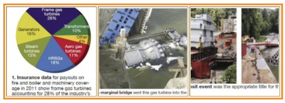
Schubert next ran through a list of plant-level insurer issues and concerns before moving to lists of specific concerns associated with each of the gas-turbine OEM’s machines, and with steam turbines and generators in general. This portion of the program certainly was of great value to attendees looking for guidance on where to invest their maintenance dollars. Sprinkled throughout were photos of equipment losses you might never think possible— such as equipment not clearing underpasses, bridges collapsing because of overloads, rigging failures, etc (Figs 2, 3). Here are a few take-aways from the balance of the presentation:Insurers will remain concerned until a root-cause analysis is completed and engines throughout the fleet are fixed accordingly. Consider the insurer’s position: An OEM may say a given problem has been corrected with a design upgrade, but that doesn’t address existing equipment—it still has the flaws.
-
Damage from a roll of paper towels left in a gas turbine wound up costing $18 million.
-
No dollar value was mentioned for the ladder left in a gas turbine.
- Insurance carriers typically have several levels of coverage for you to choose from, the most affordable of which covers only damage to a specific row or component, not downstream damage or issues related to design flaws.
- Insurers are quite concerned about the potential for bolt-type turbine overspeed trip systems to not function as intended because of varnish, sticking, spring failure, etc. Schubert’s suggestion: If you still have a bolt, convert to an electronic trip system.
-
Use of vibration monitoring and other diagnostic systems equate to lower risk, lower premiums.
-
Insurers consider machines installed more than five or six years ago and cycling frequently as failure prone.
-
Generators have been problematic recently. The last eight losses had slot movement and end-turn vibration exacerbated by cycling.
-
Supply-chain concerns for components such as castings are huge.
-
Fire protection systems: Make sure they’re up to date and meet all applicable codes—such as NFPA 850.
O&M, business practices
Ron Munson’s presentation on the importance of user participation in end-of-life assessments for major components of combined-cycle plants highlighted the O&M and Business Practices session on the afternoon of the first day. Bill O’Brien, VP, Entegra Power Group LLC, chairs that roundtable; Dariusz Rekowski, NV Energy’s generation executive, is vice chair.
Munson, a registered professional engineer, runs the small metallurgical engineering and materials consulting firm that bears his name from offices in Round Rock, Tex.
 End-of-life assessments have been a growing business since OEMs announced limits on operating hours and starts for their gas-turbine rotors a few years ago. With gas prices low, engines are running more and many plants are rapidly approaching decision deadlines, recognizing shop times for inspections, overhauls, upgrades, etc, may have to be booked as much as three years in advance.
Relatively few plant managers are familiar with the metallurgy of their equipment and the damage mechanisms that limit component lifetimes. In the time available, Munson helped attendees focus on what was important to know and how not to get tangled up in a sales pitch. With new engine orders down, the OEMs will pushing hard to get this business and it’s easy to overspend if you’re not careful.
Munson told the group that there are these three general approaches to GT life extension:
-
Accept OEM recommendations as gospel and follow their guidelines. This is the lowest-risk alternative and also the most costly.
-
Ignore all recommendations and proceed with business as usual. This is the lowest-cost alternative and also the most risky.
-
Decide on an acceptable level of risk, define which damage mechanisms can cause a failure, and address only those issues in formulating a life management program.
He then suggested that owner/operators might work together, possibly through a user group, to agglomerate knowledge and challenge the OEM’s recommendations. A couple of user groups already are doing this.
One of the most helpful parts of Munson’s presentation was the following checklist of parts to evaluate and damage mechanisms of concern:
-
Inlet guide vanes: wear, corrosion/ erosion, fatigue, mechanical damage (impact).
-
Rotor shaft: marriage coupling damage (wear, galling, cracks), bearing journal scoring and rubbing.
-
Engine supports: wear, distortion.
-
Casings and cylinders: distortion, wear, thermal mechanical fatigue, embrittlement/degradation.
-
Exhaust cylinder/manifold: thermal mechanical fatigue, embrittlement/ softening, creep/distortion.
-
Inlet plenum: corrosion/erosion, mechanical damage (impact).
-
Compressor discs: Mechanical fatigue (high- and low-cycle fatigue), wear loss of dimensions, distortion (rim bending in air flow direction), metallurgical ageing (latter stages).
-
Turbine discs: creep, metallurgical alteration, blade-root wear, fatigue (especially thermal mechanical fatigue), interference fit between discs and transition pieces.
A summary of OEM and model-specific advisories compiled by Munson serves as a handy reference. Outlined below are some key points that he highlighted.
GE Power & Water
Life limits of Cr-Mo-V turbine rotors. GE TIL 1576 summarizes the company’s position for its frame engines. In brief it limits rotor life to 5000 factored starts and run time to 200,000 equivalent operating hours, whichever comes first. Munson’s critique:
-
Assumes temper embrittlement features of Cr-Mo-V rotors. “Technology transfer” is from the company’s steam-turbine knowledge base, which really doesn’t relate.
-
There are no supporting engineering evaluations, just some dimensionless tables and graphs.
-
Does not consider the “goodness” of modern steels as compared to the air-melted steels of older turbines. What’s the pedigree of materials? Munson asked rhetorically. Vacuum-melted steels are different than those of the past.
Status report: There have been no known failures to date from a lack of conformance to GE TIL 1576.
Hot-section disc issues on 7FA and 9FA engines. Issues are addressed by various Technical Information Letters: 1539-2, Shot peening (non-contoured); 1540-2, Shot peening (contoured); 1327 and 1434, Eddy current inspection for cracks.
Status report: There have been two catastrophic failures and more than 25 discs have been found with cracks. All cracks are in square cooling-slot profiles.
Life limits on GE LM engines. A 2004 service bulletin covering all LM engines limited the lives of certain components to 50,000 service hours. Tracking of engines by serial numbers began at that time. Discs are not traceable to engine serial numbers, but discs now are tracked by their own SNs. Issues include creep, thermal mechanical fatigue, and metallurgical alteration.
Alstom Power
11N/13N rotor life exhaustion. Rotor life is limited to 130,000 hours because of concerns over (1) creep in the fourth-stage turbine blade root and (2) L-bore cracking, thermal mechanical fatigue, and creep. Recall that the L-bore allows air to pass from the first-stage disc face to cool R1 turbine blades. The company has a program to correct L-bore issues but the solution for fourth-stage creep is rotor replacement.
Status report: There has been no evidence to date of creep damage on rotors having recorded more than 100,000 operating hours. More specifically, there has been no visible plastic deformation or cracking and there have been no eddy current indications. However, there has been some thermal softening on Stage 1 (about 10 to 20 points on the Brinell hardness scale).
Siemens Energy
Lifetime extension (LTE) program. The Siemens LTE approach is relatively straightforward:
-
Evaluate fleet history and identify generic design issues.
-
Conduct unit specific evaluations.
-
Disassemble the engine and perform detailed NDE and dimensional inspections of component parts.
-
Reassemble the engine with existing and/or new parts.
Issues addressed by the LTE program include the following:
-
Temper embrittlement of both hot section rotor discs and the last several compressor rotor discs.
-
Wear of blade slots, turning gear, and sealing grooves.
-
Metallurgical deterioration of the turbine cylinder from graphitization (greatest concern is in the welds and heat-affected zone).
-
Thermal mechanical fatigue and creep of turbine discs.
-
Wear and distortion of engine supports.
-
Ovalization and creep of compressor discs in hot areas.
-
Wear, erosion, and/or corrosion in the air inlet.
-
Thermal mechanical fatigue, creep, and loss of properties (from ageing) in the exhaust section.
Wheel failure
All gas turbines are unique, despite model numbers that might argue otherwise. In engineering school, students were introduced to the bathtub curve—at least they were decades ago. The basic idea was that after a relatively short break-in period component reliability remained virtually constant until end of life, when it dropped off the proverbial cliff.
Most students didn’t pay much attention to the word “component” and fewer still probably read the fine print, which talked about the general applicability of the curve to electrical and electronic components, but not to complex systems.
Reliability theory aside, many GT owners believed that “fleet issues” associated with each engine model eventually would be resolved. In many cases they have been, but in others they have not. New problems seem to surface more frequently than one would expect for an ageing fleet, in some instances probably because the design of a given engine continues to evolve.
Example: The thinking by some in the industry is that the clashing of Row 1 and/or Row 2 stationary and rotating blades in many 7EAs could have something to do with the flexing of the casing which may have been thinned by designers over the years, together with the lockup of vanes in their carriers because of rusting.
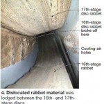
An incident described by a user at CTOTF’s Turbine Users Conference last fall suggests there may be no end to unwelcome surprises for some turbine owner/operators. A dual-fuel, water-injected 7211F commissioned nearly 20 years ago suffered a 16th-stage wheel failure that left most attendees scratching their heads. That this incident occurred after “only” about 1600 starts and 13,000 fired hours might give pause to complaints by some users regarding what they consider unreasonably short rotor lifetime limits imposed by OEMs.
A review of unit history reveals the machine had a turbine-rotor upgrade in the late 1990s and it experienced a17th-stage compressor wheel failure and upgrade to the so-called “bigger, better fillet” (BBF) five or six years ago.
The 16th-stage wheel failure occurred while the unit was being unloaded for shutdown. A vibration trip occurred below 30 MW. It was initiated by a step increase in vibration on the No. 1 and No. 2 turbine bearings, recorded on both seismic and proximity probes. An attempt to restart the unit the next day resulted in an automatic shutdown initiated by high vibration.
A borescope inspection of both the turbine and compressor revealed no problems. Also, no damage was noted external to the rotor after the upper casing was removed. But a subsequent borescope examination with the casing off identified the disc failure at the aft rabbet fit. Specifically, rabbet material was found lodged between the 16th- and 17th-stage discs (Fig 4).
 The conclusion draw by the owner’s engineers was that the BBF rotor design is not a permanent solution and users with them should upgrade to the RBE.The owner’s engineers investigated several options, including a weld repair, which was nixed because of concerns that another component might fail. No spare 7211 or 7221 rotors were available and it was unclear that a 7241 rotor would fit properly in the 7211 casing. In the end, the owner purchased a “robust back end” (RBE) compressor rotor from the OEM. This solution required machining of the distance piece to the reverse gender of the marriage coupling. Other enhancements were made as well.
Rankine considerations
Scott Wambeke, PE, one the industry’s most experienced HRSG troubleshooters, had a simple message for GT owner/operators attending the Combined Cycle Roundtable: Don’t opt for a GT upgrade before conducting an engineering evaluation to see if your heat-recovery steam generator will meet expectations with the new operating parameters.
 In a marketplace demanding greater operational flexibility to meet evolving and more stringent grid requirements, owners are considering GT enhancements such as compressor and firing-temperature upgrades, plus retrofits to enable operation at a lower minimum load and others to boost peak output. It’s important to keep in mind, Wambeke said, that implementation of any of these options will affect the HRSG.
Performance trends. He covered the potential impacts of GT upgrades—including changes in HRSG thermal performance, low-load operating issues, and possible need for a boiler capacity assessment if steam production increases. Regarding thermal performance, Wambeke offered the following insights:
-
If exhaust flow increases, expect a nearly proportional increase in steam flow, higher gas-side pressure drop, and a shift in energy absorption to the back end of the unit. The last usually means a slight bump in low-pressure (LP) steam flow and a greater risk of having a steaming economizer.
-
A higher exhaust temperature typically translates to a slight increase in steam flow, higher energy absorption by the superheater and reheater tube bundles, increased attemperator spray-water flow, and usually less LP steam production.
Compressor upgrades usually increase exhaust flow by 2% to 5%, reduce exhaust temperature by 5 to 15 deg F, produce a small net increase in steam flow, and curtail attemperator spray-water flow, Wambeke continued. He also said that firing-temperature upgrades produce little change in exhaust flow, raise exhaust temperature, increase HP steam flow by a small amount, and increase significantly tube metal temperatures and attemperator spray-water flow.
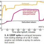
Low-load trouble spots. If exhaust temperature increases at low loads, as it does for GE F-class gas turbines, spray-water requirements may increase dramatically. Wambeke mentioned that a 1200F exhaust spike for a 7F can initiate a spray-to-saturation event (Fig 5).
Control-valve turndown can be an issue, especially when the boiler feedwater pump operates at constant speed. In such cases, valves may have to throttle to 10% to 25% of the full-load rating, increasing wear. Drum-level and attemperator control valves are impacted as well.
 Economizers typically are at a higher risk of steaming with the GT at low load, Wambeke added. Plus, buoyancy instability is exacerbated when water velocity in economizer circuits drops below a minimum value; flow stagnation conducive to fatigue failures can result.For HRSGs operating in the sliding-pressure mode, evaporator-section temperatures will drop as load decreases, the boiler designer said. A low gas temperature at the SCR location will reduce catalyst activity and may lock out the ammonia supply. Also, circulation flows in the LP economizer may change and increase the risk of flow-accelerated corrosion (FAC).
Finally, non-pressure parts—such as liner systems, perforated plates, and anti-vibration supports for tube panels—may fatigue more quickly during low-load operation when gas temperatures are significantly higher than they are at full load.
Capacity assessment. GT upgrades, such as an LM5000 to LM6000 conversion, can increase steam production to where it exceeds the stamped HRSG capacity permitted by the ASME Boiler and Pressure Vessel Code. Bear in mind that safety valves must be able to relieve the stated capacity and an exceedance is not permitted. The ASME stamped capacity can be revised, but this must be studied and documented by an organization holding an ASME design stamp prior to recertification, Wambeke told the attendees.
In addition to safety-valve capacity the following components also require review:
-
Drum steam separators. Insufficient capacity may result in carryover.
-
Reheater and superheater tube metal temperatures. This requires use of a sophisticated heat-transfer model.
-
Feedwater-pump and control-valve capacity.
-
Attemperator capacity.
-
Modeling of water flows and velocities in economizers and LP evaporator circuits to determine the risk of FAC damage.
Drowning in paperwork
The tsunami of regulations overwhelming the electric power industry has spawned a mountain of paperwork on every plant manager’s desk. While most of the model-specific gas-turbine user groups remain focused on the engine, CTOTF has expanded its coverage, in part to help owner/operators keep up with new regulatory requirements. Implementation of changes in conference content has been rapid and ongoing over the last several years.
A case in point is the Regulatory and Compliance Roundtable chaired by Scott Takinen of APS, a well-respected plant manager who recently moved up to the corporate offices as director of executive projects for fossil generation. Back in 2006, he prevailed upon then CTOTF Chair John Lovelace, an APS colleague, to launch the ZLD (for zero liquid discharge) Roundtable. No one could have imagined where that big first step away from gas turbines would lead.
Recall that in the early 2000s a movement began in California to prevent powerplants from discharging any liquids offsite. Several types of ZLD systems had been installed by the middle of the decade—all expensive and with onerous O&M requirements. Takinen was concerned that the fever might spread to other states and thought CTOTF members should explore the intent of the regulations and learn more about the mitigation technologies.
It didn’t take the forward-thinking plant executive long to bring other environmental issues under his roundtable’s umbrella. The CTOTF Leadership Committee, chaired by TVA’s Kirn following Lovelace’s retirement from APS in 2007, voted on Takinen’s suggestion to rename the session Environmental Systems and ZLD for the fall 2008 meeting. By then, ZLD furor had begun to subside and discussion of other environmental issues expanded.
Shortly thereafter, the CTOTF leadership recognized that the technologies for reducing air emissions consistent with regulatory requirements were available and generally being addressed by the various gas-turbine roundtables (low-emissions combustors, etc) and by the Combined Cycle Roundtable, which focused on the Rankine cycle. This prompted a repositioning of Takinen’s session to encompass all regulatory issues facing owner/operators.
 The Regulatory and Compliance Roundtable debuted in 2010. The following year, vice chairs specializing in air/water and NERC/FERC regulations were elected. Today those positions are filled by Kimberly Williams of NV Energy and Alan Bull of NAES Corp, respectively, both experts in their fields.
When Takinen talked-up the ZLD Roundtable in 2006, most attendees were left scratching their heads, and the generally persuasive plant executive was hard pressed to get 10 participants in his session. In just a few short years, participation has grown to about one-third, or more, of the conference attendees. And, because subject areas requiring discussion continue to increase, the Regulatory and Compliance Roundtable at upcoming spring meeting will run a full day, up from the traditional four-hour session.
Alphabet soup
That the Regulatory and Compliance Roundtable provides technical information attendees can put to immediate use at their plants as well as valuable perspective on the direction of both changing and new rules, regulations, and legislation was illustrated by the following lineup at last fall’s session:
-
Mark Haughn of APS addressed NERC-required plant documentation for Critical Infrastructure Protection (CIP).
-
Dan Ott, VP of Industrial Catalyst Services at Environex Inc, helped owner/operators get a firm grip on SCR catalyst O&M.
-
Julie Mitchell of URS updated attendees on air permitting requirements for new and modified gas turbines.
-
Shirley Pearson, PE, of URS spoke on new source performance standards.
Haughn is a full-time member of a six-person team responsible for developing, supporting, and implementing APS’ enterprise-wide CIP compliance program. In April 2011 the APS team received the first zero-finding CIP audit conducted by the Western Electricity Coordinating Council. Two of Haughn’s other responsibilities: Modernize and make CIP compliant 20 substations and a coal-fired powerplant; conduct CIP training throughout the company. Point of the summary resume: Haughn knows CIP.
A primary objective of his at the CTOTF meeting was to make attendees aware of CIP Version 4’s significant impacts before the standard “goes live” Apr 1, 2014. V5 is expected to follow in early 2015. The expert said achieving compliance with V4 will require about 18 months of effort, which means it’s a critical-path item right now. He added that the only difference between the current V3 and V4 is CIP-002, “Critical Asset Assessment.”
In V3, owners of critical infrastructure conducted their own assessments to determine what a critical asset is. The standard required risk-based assessment methodology. V4 requires a criteria-based assessment and if certain well-defined criteria are met then the asset is a critical one. Example: Every black-start resource identified in the transmission operator’s restoration plan is critical.
CIP terms generally don’t mean much to most plant personnel at first blush; however, their impact will be a more restrictive life on the deck plates. Plus, there will be more paperwork, more reporting, potentially more cyber and physical security at the plant, additional CIP audit scope, etc.
To illustrate the big difference between Versions 3 and 4, Haughn said that the number of devices related to plant operations that come under the compliance umbrella as defined by V3 is 119. Under V4 it will be in the neighborhood of 1500. Also, expect that the compliance costs associated with certification of remote sites will be much more costly under V4 compared to V3.
After reviewing CIP-002, Haughn gave an overview of standards CIP- 003 through CIP-009. It included what evidence of compliance is required, at what intervals the evidence must be complied, and how the evidence must be delivered for proof of compliance. In conducting this review, he mentioned that CIPs 004, 5, 6, and 7 accounted for the most write-ups and fines.
Haughn also covered the filing of Technical Feasiblity Exceptions, as well as self-reports, which document admissions of violations. An overview of training required under the CIP standards and audit evidence requirements closed out the presentation.
 Ott, who has an advanced degree in chemical engineering, is known to CTOTF members for his deep knowledge of emissions-control technology. The article developed from his presentation in spring 2008 (“SCR working well? Don’t take that for granted”) covers some of the same material that he spoke to in San Diego because the basic technology has not changed much but the audience has, with more than 40% of this fall’s attendees first-timers. His review of the basics certainly was in order.
The trend is to less catalyst—just enough for suppliers to meet their guarantees. Some of the early SCR catalyst beds lasted 10 years or more on GTs burning only natural gas. Providing more product than required was adversely impacting supplier balance sheets.What follows are several important points made by Ott which were extracted from the editor’s notes. Users have access to the actual presentation via the CTOTF Presentations Library at www.ctotf.org.
-
Fast-start units are expected to require more catalyst than normal-start GTs because the catalyst can’t “catch up” with NOx produced early in the operating cycle, when design operating temperatures have not yet been achieved. More catalyst is required to make an effective “sponge” for the pollutant.
-
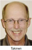
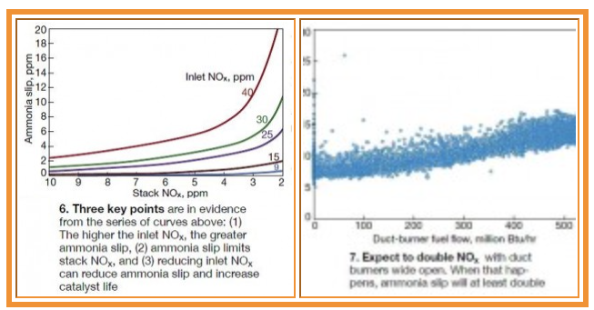
It is important to monitor SCR inlet NOx to assure meeting emissions expectations. Ott put up on the screen a series of curves that shows you should be at 15 ppm inlet NOx if you expect to achieve 2 ppm NOx at 2% ammonia slip as some regulations require (Fig 6).
-
Expect to double NOx with duct burners wide open as the chart agglomerating data points for an F-class unit reveals. When that happens, ammonia slip will at least double (Fig 7).
-
Ammonia slip increases as catalyst ages. Near the end of life slip increases exponentially as catalyst deactivates—so-called ammonia “breakthrough.” If your monitoring of ammonia slip reveals a relatively small but increasing value over time, particularly when the catalyst is young, double-check to be sure inlet NOx is not off-spec. The catalyst may be blameless.
-
Monitor pressure drop across the SCR catalyst to check for fouling; monitor ammonia consumption to check for catalyst deterioration, and maldistribution of the reagent. If fouling occurs, it may be caused by fine dust released from the upstream CO catalyst. Cleaning of the SCR catalyst—back blow with air or vacuum—can bring the pressure drop back within spec. Periodic cleaning of CO catalyst also is a good idea. Plugging of the CO catalyst is one of several reasons for uneven distribution of ammonia across the face of SCR catalyst, and it can contribute to an increase in slip. Ott mentioned a case where cleaning of the CO catalyst lowered ammonia slip at the stack by 2 to 3 ppm.
-
Ott urged attendees to write tight specifications for replacement catalyst and to buy only a top-quality product.
-
Tuning of the ammonia grid was included in Ott’s presentation, of course. But by the time he got to that part, Takinen, hammer in hand, was ready to hit the gong.
Mitchell’s and Pearson’s presentations were especially valuable for a plant manager planning to modify an existing unit and not supported by a staff of headquarters engineers that includes one or more environmental experts. The operative word in the first sentence is “modify.” Your definition and that of the regulatory authorities—particularly those at the state and local levels—might be miles apart. If want an answer to one or more of the following questions read through both presentations, which are posted to the CTOTF Presentations Library:
-
How do the new National Ambient Air Quality Standards (NAAQS) impact planned new units and modifications to existing gas turbines?
-
What is the relevant content of the New Source Performance Standards (NSPS) for stationary gas turbines?
-
What are the five steps to the Top-Down BACT (Best Available Control Technology) process?
-
Must I install the “best available” technology?
-
What can I do to eliminate costly or inefficient technologies from further consideration?
-
How has the five-step BACT process changed with the addition of greenhouse gases?
The answer to the first question, presented by Mitchell, covered the NAAQS standards for NO2 and PM2.5, relevant facts on each pollutant, and attainment status. Who is affected, what triggers dispersion modeling analysis, analysis methodologies for the pollutants, and other relevant topics were reviewed by the speaker.
Mitchell also provided case histories of two projects struggling to show compliance and answered the question no one wants to hear: What if significant impacts are predicted by modeling? Another valuable part of the presentation was a reference list of important EPA documents covering the main topics Mitchell discussed.
Pearson addressed the remaining questions. Her slides provide considerable detail and are easy to follow.
Generators
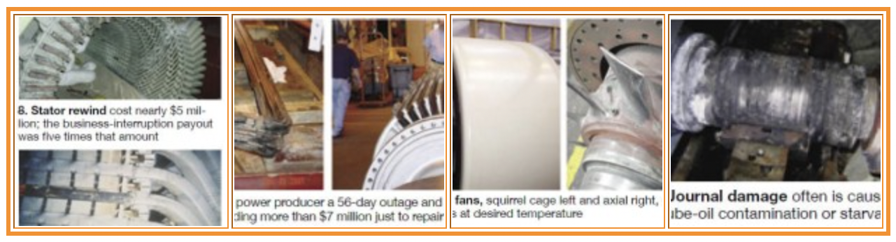
When Don Schubert, senior VP of Marsh Energy Practice, told participants in the opening session of the CTOTF fall meeting that generators accounted for 16% of insurance losses in 2011, there was a look of disbelief on some faces. The reliability of generators typically has been “taken for granted” by the industry. But eight generator losses last year, attributed primarily to slot movement and end-turn vibration exacerbated by cycling, point to the need for closer attention by plant operating staffs (Figs 8-10).
Generator reliability has been decreasing over the years for several reasons, among them:
-
Tighter design margins. Someone pointed out in the open discussion that back in the 1930s generators weighed six times what they do now on a kilovolt-ampere basis. Today’s design tools contributed significantly and positively to the reduction in bulk. However, the goal of ever tighter design margins often is driven by customers wanting to pay less for their equipment. “Be careful what you wish for” applies here.
-
Loss of continuity in OEM engineering expertise. Some of the generator issues in evidence today were identified years ago—back in the 1940s, 1950s, and 1960s—and corrected by design engineers. But during the transition to leaner OEM staffs in the 1980s, some top managers were more concerned about immediate reductions in “head count” than about focusing on retaining the company’s knowledge and ability to compete in the future. The result: Some of yesterday’s problems have resurfaced and must be re-solved. Access to retired OEM generator engineers may be one of the reasons several third-party generator inspection and repair companies, and consultants, have been quite successful of late.
-
Transition from a regulated to a deregulated electric-power market. Electric utilities are (or at least used to be) deep in electrical engineering talent to keep a watchful eye on generators, transformers, and high-voltage (HV) switchgear. By contrast, most independent producers have a few (in some cases only one or two) overloaded engineers assigned to those duties. Further, parsimonious staffing at independent powerplants, and a general reluctance of deck-plates personnel to approach unfamiliar HV equipment that hums, sparks, and arcs, often leaves generators without a staff champion.
-
Higher ratings—kV and kVA—for air-cooled generators are challenging today’s perceived technology limits.
The foregoing, of course, is not new to senior personnel at the nation’s generating stations, which is why CTOTF’s Leadership Committee has committed to supporting a one-day roundtable dedicated to generators, HV electrical gear, and I&C at its semi-annual meetings. This is significantly more “air” time than generators get at most user group meetings in this sector of the industry. This portion of the CTOTF program is chaired by Moh Saleh of Salt River Project; vice chair are NAES Corp’s Craig Courter and Braintree Electric Light Dept’s John-Erik Nelson.
CCJ has followed CTOTF’s lead by expanding its coverage of generators, primarily in association with Consultant Clyde Maughan, who has contributed several articles on their inspection, troubleshooting, and maintenance over the last couple of years. Access the generator article library page of www.ccj-online.com/maughan. Also, you can find 10 hours of recorded webinars from Maughan’s course, Generator Monitoring, Inspection, Maintenance at www.ccj-online.com/onscreen.
More information on generator design, operation, and maintenance of value to plant personnel can be accessed through CTOTF’s Presentations Library. Plus, an extensive collection of technical papers on generators—including six decades worth of Maughan’s writings—is available at www.GeneratorTechnicalForum.org the home of the all-volunteer International Generator Technical Community. Both of these websites also support online forums to help you get answers to questions.
Generator auxiliaries. The overwhelming majority of generator presentations at user group meetings focuses on field (rotor) and stator windings—inspection, testing, maintenance, replacement, upgrade, etc. While they may be the most important parts of the generator—especially in the minds of the OEMs and third-party services providers who provide replacement coils—Saleh and his vice chairs know from experience that the failure of a key auxiliary can take you out of service just as quickly.
W Howard Moudy, director of service management for National Electric Coil, lead a discussion last fall on generator auxiliaries both to acknowledge the importance of these components and suggest ways to mitigate the risk of their contributing to the extension of a planned outage, or causing a forced outage. Moudy, highly visible at user-group meetings, dedicates a considerable amount of time to helping owner/operators assure top performance from their generators through application of best practices and lessons learned.
The generator expert began with an overview of cooling systems that highlighted areas of concern with each. The most common form of cooling, Moudy said, was air, with the leading technology alternatives being OAC (open air cooled) and TEWAC (totally enclosed water-to-air cooled).
The biggest challenge for these units, he continued, is cleanliness, stressing the importance of quality, long-lived, low-pressure-drop filters to maximize the time between generator cleanings and help maintain optimum output. Recommendations: Prefilters to protect final filters, the latter having Ashrae MERV ratings from 13 to 16.
Keep in mind that entrained oil contributes to loose coils, which are conducive to abrasion to ground insulation. Water-cooled generators require demineralized water to circulate through hollow conductors in stator bars. Pumps, filters, valves, meters, and special fittings are auxiliaries of interest.Hydrogen-cooled generators have several important components that benefit from close monitoring. These include rotor fans to circulate the gas, coolers to maintain the optimal winding temperature, and dryer skids for maintaining hydrogen purity. It’s important to keep hydrogen clean and dry.
 Moudy spent about 10 minutes on excitation systems, including their testing, before moving on to rotor fans, which may be of the squirrel-cage or axial type (Fig 11). He mentioned to attendees that generators designed by GE have two fans—one at either end of the generator rotor. By contrast, those of Westinghouse (now Siemens) design have one fan mounted on the turbine end. Moudy warned against attaching balance weights to rotor fan blades.
Tips on preventing/correcting bushing issues—such as overheating, deterioration of gasket/sealing material, and cracked porcelain—came next, followed by discussion of collector rings, brush holders, and brushes. Recall that the collector ring is the rotating member, shrunk-fit on the rotor shaft over an insulated sleeve, which collects excitation direct current from carbon brushes and brings it to the field winding via special connections. The collector-ring surface usually is grooved to even out brush wear and reduce sparking.
Collector rings vary in size and number—depending on how much current must be supplied to the field. Rings wear over time, often unevenly, and require periodic truing. Carbon dust is a byproduct of the wear and tear and it can accumulate and harden in brush boxes, preventing the free movement of brushes. This condition, as well as weak springs, can compromise brush-to-ring connections and cause arcing. Ring fires may result.
Moudy concluded with his thoughts on journals and bearings. He showed some ugly photos of journal damage, which usually is caused by lube-oil contamination or starvation (Fig 12). Serious damage can occur, resulting in major repairs to the rotor forging. Very serious damage may require cutting off the affected area and the welding on of a new stub shaft. Minor damage occurs over time because of impurities in the lube oil and it typically requires just honing and/or polishing to correct.
Ring fire
The morning after NEC’s Moudy spoke to attendees about the risks associated with ignoring OEM-suggested maintenance of exciter collector rings and brush systems, Cutsforth Inc’s Senior Application Specialist Steve Thompson called the editors to report a damaging ring fire that required immediate attention.
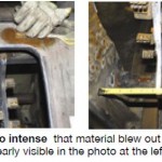
Plant personnel told Thompson the fire was so intense that material literally blew out of the housing, as evidenced by the holes shown in Figs 13 and 14. Cutsforth normally is able to repair/refurbish/upgrade brush rigging onsite, but the severity of the damage here was such that the entire housing required a shop visit for a complete rebuild.
 Thompson said Cutsforth is seeing an increasing amount of work from the 7F fleet. One reason, he believes, is because low gas prices have owners running units base-load that had been in daily-start and peaking service. Here’s what Thompson sees as the root causes of the recent damage:
-
Brushes never have to be changed online when turbine/ generators are in daily-start or peaking service. Apparently, some deck-plates personnel were not trained in online inspection and replacement of brushes before the shift to base-load operation and this critical work was not being done, thereby allowing the opportunity for exciter brush systems to spark and arc their way to destruction.
-
Weak brush springs are a big issue, Thompson continued. Many have not been changed—ever. Most units in the 7F fleet were installed during the bubble and typically are from eight to 12 years old. Springs lose their “spring” whether you run or not. Combine carbon deposits from increased run time and weak springs and you have the perfect recipe for selective action, which is conducive to overheating and fires.
-
Mixing of brushes is contributing to or directly causing some ring fires. Having a matched set of brushes is important: Do not mix brushes manufactured to different specifications. Proper brush composition and dimensions, and lead current-carrying capacity, are critical to success. Allowing purchasing agents to ignore your directions and buy from irresponsible offshore suppliers creates safety issues.
GE legacy engines
Meeting after CTOTF meeting, every seat is occupied at the roundtable dedicated to GE E- and legacy-class engines. There are two obvious reasons for this: First, there’s a slew of Frame 5, 6B, and 7B-EA engines in electric generation service in the Western Hemisphere; second, in an era where real content and critical discussion are king, this session never disappoints.
Less obvious is that the session chair—Pierre Boehler of GenON Energy—and vice chair—Ed Wong of NRG Energy—are among the industry’s O&M technology elite with long experience. Boehler, in fact, was a founding member of the 7F Users Group more than 20 years ago.
At the fall meeting, Boehler’s and Wong’s session featured the following in-depth technical presentations:
-
Profile of a major inspection by a user.
-
“How to Inspect, Repair, or Replace GT Inlet and Exhaust System Components,” by David Clarida, Integrity Power Solutions LLC.
-
“Frame 6 Gear Drive O&M Considerations,” George D Lankford, Philadelphia Gear Corp, a Timken company.
-
“Gas Turbine End of Life,” Paul Tucker, First Independent Rotor Service of Texas (FIRST).
Outage profile
A user focused on highlights of a major inspection for a Frame 7 unit which was particularly valuable for the open discussion it created. Best practices, lessons learned, and issues requiring solutions also were included in the presentation, based on experience with the unit that underwent the major, plus several others in the owner’s fleet.
First best practice: Inspection checklist for inlet air houses and associated ductwork for cold-climate readiness. It was developed for the owner’s Gulf Coast plants, three of which had suffered compressor damage from ice the previous year during a prolonged cold snap. A primary objective was to inspect Frame 7 E-class units for potential water-ingress sources to mitigate potential FOD from ice formation. The following are key elements of the program:
-
Check the inlet screen and swing gate for integrity and operability; repair as needed. Access is by rolling scaffold or forklift with basket.
-
Inspect inlet house and associated ductwork (access via scaffold or forklift through the swing screen) for potential water ingress using a light source. Check silencers and trash and bird screens for damage. Spray water over the inlet house and ductwork from an aerial lift and inspect internally for water ingress. Make repairs as necessary.
-
Conduct a similar inspection (as described in the second bullet point) of the bellmouth inlet duct/elbow area.
-
Make a final walk through of the areas accessed to be sure people, tools/equipment, and repair materials have been removed and the units is fit to return to service.
Second best practice. The presenter’s description of repairs made to the Row 4 vane-carrier slot rail, which had cracked at the fifth-stage air extraction (Fig 15), was of considerable interest, judging from the body language of attendees. The forward compressor case was removed (Fig 16) and a patch ring was machined and installed in the vendor’s shop (Figs 17 and 18). This 30-in. circumferential case crack resembled ones often experienced on Frame 5s, but those are found further back in the compressor.
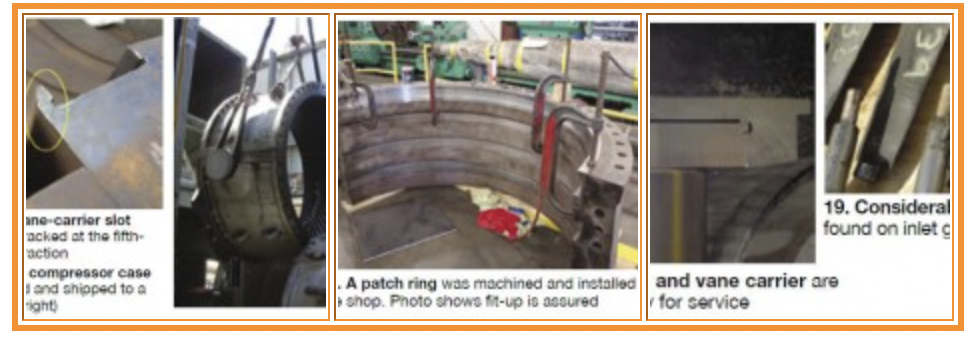
Lessons learned can be painful. A significant portion of the presentation addressed compressor stator vane and shim migration issues for Stages 1-8. Recall that the first four stages each have six vane carriers into which the airfoils are inserted; Stages 5-8 have individual vanes. A non-OEM supplier was selected to provide replacement stator hardware for the first eight rows. Existing vanes were retained in the downstream stages, where shim migration was addressed by pinning.Other best practices included the plant’s positive experience with non- OEM combustion hardware and with the use of remote video inspection tools to assess generator condition. Use of Nimonic forged cast aft mounts on transition pieces have had a positive impact by shifting dynamics to higher frequencies. Condition of the mounts was rated “good” during an inspection after nearly 800 starts. Inspection of low-residence-time fuel nozzles revealed similarly good results—no issues after more than 600 starts.
There were fit-up issues with the new vanes for Stages 5-8. The individual vanes wouldn’t slide into the case on the first attempt and their bases had to be beveled. Vane bases also were found undersize and shims were required to set the horizontal-joint gap and pinned to the vanes. Finally, vane tip heights were too short. The vane carriers for the first four compressor stages were provided slightly longer than required and field-machined to fit exactly without the need for shims.
Pitting of inlet guide vanes was identified and addressed (Fig 19).Several more issues had to be resolved during the outage to assure reliable service going forward. Among them:
-
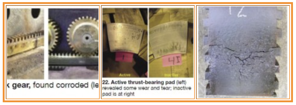
Corroded rack gear was removed (Fig 20) and new pinions and rack were installed (Fig 21).
-
Bearings revealed some wear and tear. Compare typical as-found active and inactive thrust pads in Fig 22.
-
Significant wear and tear was found on both first- and second-stage shroud blocks (Fig 23).
-
Turbine case cracks are a recurring problem and are repaired every outage.
-
Exhaust-case cladding damage is an ongoing battle as well.
Inlet, exhaust systems
David Clarida is well known to CCJ subscribers for his insightful article on gas-turbine exhaust systems in the 2010 Outage Handbook and his recorded webinar on the same topic. It covered virtually all of what Clarida had to say at CTOTF on exhaust systems. Not covered, however, were his comments on inlet-system inspections.
The most common inlet-system concerns of owner/operators, Clarida said, are the following:
-
Safety—inlet acoustics.
-
Operations—engine compressor FOD (foreign object damage) and deposits.
-
Maintenance—inlet corrosion.
-
Performance—equipment failure, high pressure drop.
To address these potential issues, Clarida suggested checking the inlet system thoroughly before each outage. His key points were:
-
Develop an inlet acoustic-performance baseline.
-
Listen for internal noise so you don’t miss a possible failure in the internal insulation system.
-
Inspect expansion joints for breaches that allow unfiltered ambient air to enter the compressor.
-
Inspect for other avenues for air bypass, including shell-plate corrosion, improper sealing of filter elements, etc. It’s easy to find holidays in the shell of the inlet air house and associated ductwork by standing inside the darkened structure on a bright sunny day (with the engine off, of course) and looking for rays of sunlight.
-
Evaluate the inlet system to see if it’s compatible with the actual operating environment. Oftentimes little real engineering is done on inlet systems during the plant design phase and the “standard” components installed may not be meeting expectations.
-
During the outage, he recommended checking the following:
-
Integrity of internal insulation and liners.
-
Internal corrosion.
-
The entire filter house for proper installation of filter media and evap-cooler media or fogging nozzles, if installed.
-
Integrity of the inlet trash screen.
Load, accessory gears
Philadelphia Gear’s Lankford is the type of speaker users want to listen to—knowledgeable, with an easy presentation style. He has lived gears virtually every day since joining the company in 1978 as a design engineer and has had years of deck-plates responsibility for the overhaul, installation, and alignment of load and accessory gears for gas turbines. Plus, he is a Level II certified vibration analyst. Lankford “knew” the people he was addressing and what their information needs were.
While the speaker’s assignment was to focus on O&M considerations for Frame 6 gears, gears are gears and his presentation was of high value to most attendees who did not have 6Bs in their equipment stables. Lankford began by listing several “must-dos” to guide your maintenance program and avoid gear problems to the extent possible. Here’s what he suggested:
-
Look at trend data, not single data points.
-
Be consistent during data acquisition.
-
Automate recordkeeping to allow rapid evaluation of data.
-
Know your equipment baselines, taken at startup and after repair.
-
Identify and maintain access to critical spares.
-
Buy OEM quality replacement parts.
Next, he identified the following as criteria for repair based on the results of inspections and monitoring activities:
-
Visual inspection. Significant shift tooth contact pattern, rapid change in the level of tooth wear, and significant levels of metallic debris.
-
Vibration. Significant increase in vibration amplitude at the equipment’s predominant frequencies in any plane.
-
Oil sample/wear particle analysis. Significant increase in high-alloy steel particles (from gears) and/ or in bronze, tin, or lead particles (from bearings).
-
Noise and temperature. Significant change in noise level or the identification of unusual noise; significant increase in oil temperature.
Lankford reviewed vibration basics, such as a signature that is 1 × shaft rpm points to a single gear tooth defect or rotor unbalance; 2 × shaft rpm indicates axial misalignment. He urged attendees to avoid the temptation of becoming an amateur vibration expert. Leave vibration analysis to those trained in the science, he said.
Data are easily misinterpreted and only the trained eye will likely spot such things as an improper transducer, poor choice of data points, etc. The experienced analyst has the background to determine if the reading obtained is reasonable and if other symptoms agree with the finding.
Proper tooth contact and how and when to check for it got its share of air time as did ways for correcting misalignment, if found. Apply hard blue during each outage was the suggestion made to users for identifying uneven wear; look for changes over time by comparing current photos with those from past years. Optimal condition is a centered wear pattern tapering off at each end (Fig 24). Unacceptable tooth contact is illustrated in Fig 25.
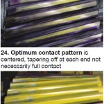 The causes of poor contact include these:Lankford paused to explain more about bluing. Use soft blue, he said, when the accessory gearbox is disconnected from the turbine during an outage and the gears can be turned by hand to see the contact area. Use hard blue when the gears are coupled to load.
-
Excessive bearing clearance or damage
-
Housing bore damage or misalignment.
-
Uneven foundation or improper support (soft foot).
-
Gear geometry mismatch.
-
Shaft, casing, or tooth deflection under load.
-
Thermal distortion under load.
-
Component-to-component misalignment.
Correction of poor contact may require resetting or replacing bearings, remachining the casing, reshimming the casing/fixing the foundation, and/or compensating for deflection and thermal distortion with modified geometry (lead modification).
Lankford stressed that a properly maintained and operated gearbox should operate trouble-free without an overhaul for its design service life of 20 years or more. Only when issues are identified by an adequate condition monitoring/preventive maintenance program should the decision to teardown, inspect, and overhaul a gearbox be made.
The gear expert said, “When you take apart a perfectly serviceable gearbox, the probability of doing more harm than good is greater than any of us care to imagine.” Contamination ingress, improper fit-up of parts, the risk of breaking hard-to-access components (such as thermocouple wires), etc, militate against teardown unless absolutely necessary.
Rotor end-of-life inspections
OEMs tell users their gas turbines have critical parts with finite lifetimes and that replacement of these parts may be necessary to assure reliability and safety moving forward. Rotors are a primary target of this initiative. Today, the only way to determine if an ageing rotor is in sufficiently good condition to continue operating is to disassemble it and to nondestructively examine individual wheels, bolts, etc.
Tucker’s company, FIRST, is one of relatively few third-party service providers experienced in end-of-life (EOL) rotor inspections on Frame 5s and 7B-EAs. Some of the firm’s early work was presented at CTOTF’s fall meeting in 2007. The subject of that report was a 7C rotor from a 1 × 1 STAG 100 combined cycle installed at Arizona Public Service Co’s West Phoenix Generating that had more than 6000 actual starts at the time of the inspection; it is still operating today.
The rigorous inspection program conducted revealed no reportable indications. This led the inspection team to conclude, based on inspection-process fidelity, inspection methodology/ criteria experience, and the excellent inspection report, that it was “more than reasonable to assume no defects would grow and propagate into anything near critical flaw size in the next major inspection interval.”
Inspections conducted by FIRST to determine if an engine is fit for duty include the following:
-
100% three-dimensional boresonic inspection for internal flaws.
-
Eddy-current inspection for creep.
-
Hardness and replication for grain structure.
-
Critical diameters measured for bore shrinkage.
-
Finite element analysis (FEA) when flaws are identified.
Regarding the last point, FIRST and its business associates have developed rotor-component fracture models to perform FEA analyses when needed. Tucker said that FIRST’s critical-flaw-size and fatigue-life estimations enable the company to analyze flaws with its models to see if flaw characteristics are detrimental to machine operation. He said the models can determine if specific flaws will fail, and if so, when in terms of hours and/or starts.
 For Frame 5P EOL inspections currently being conducted in FIRST’s Houston shop, Tucker is checking compressor wheels for rows 13 to 16, the distance piece, and both the HP and LP turbine disks. In one of the machines, a flaw cluster in the HP turbine wheel was identified during the phased-array ultrasonic inspection. FEA analysis suggested that this wheel not be returned to service.
More recently, FIRST found a flaw in the 16th-stage compressor wheel of a Frame 5 rotor with 4800 starts. FEA analysis showed it to be “non-detrimental.” Tucker pointed out that the material used for compressor wheels is more forgiving than that used in the manufacture of turbine disks. He stressed, “What you might find is not always bad,” mentioning that some users he speaks to believe a material defect means the part must be scrapped. Not true, Tucker continued, it’s not a “gloom-and-doom” thing.
Inspections conducted by FIRST nominally take five days; however, analysis of any flaw that might be found can add a couple of weeks or more to the schedule. Tucker suggested to the owner/operators that they do an EOL inspection earlier rather than later—during a major or when they are going to replace compressor blades.
Having a baseline condition assessment enables users to better manage the lives of their rotors, he said. Plus, if it appears that one or more components will have to be replaced in the future, knowing earlier allows owner/ operators to plan for that eventuality and to order refurbished or new parts on a standard delivery schedule. CCJ