


Beluga personnel install new wheels on Frame 7 turbine rotor at 200,000 hr
(Click on thumbnail photos and diagrams to enlarge.)
The hot topic at most gas-turbine user-group meetings today is rotor life evaluation. Recall that the OEMs have established life limits on turbine rotors that strongly suggest their replacement at a prescribed number of operating hours or starts, whichever comes first.However, rotors that have hit their hours limits may not have to be scrapped provided comprehensive nondestructive examination (NDE) and engineering evaluations indicate safe operation is possible for another major inspection cycle—50,000 hours is the number heard most often. Extending the run time of rotors that have hit their starts limits is still a matter of debate.The OEMs and a few third-party shops see significant business coming their way as the nation’s gas-turbine fleet ages. The manufacturers are sure to be the big winners because they can examine an existing rotor and recertify it for continued use if it passes inspection or they can sell you a new rotor if it doesn’t. If the latter option is pursued, the GT owner might get a credit for the old rotor, which the OEM could then cannibalize for parts or refurbish and lease or sell for say 50,000 hours of service.
Among the first large frame engines to bump into rotor life limits are the E-class machines, many of which have been in service for more than 30 years. In the GE 60-Hz fleet, this includes 6B, 7B-E, and 7EA gas turbines. In sum, about 1000 units have been installed for producing power in the US.In addition to this group of rotor-overhaul candidates, there are many more of the smaller and generally older Frame 5s requiring life management services. A few years ago, many in the industry believed that most Frame 5s would be pushed into retirement, but lower gas prices and the value of these engines for supplying grid ancillary services have extended their lifetimes. Interestingly, Beluga’s Frame 5s have at least 25% fewer operating hours than the plant’s E-class turbines.
Several E-class machines have reached the 200,000 hours or 5000 starts limits established by the OEM and have been replaced or inspected/evaluated/reconditioned for extended service. In general, the likeliest of candidates for rotor replacement—the most expensive option—would be GTs serving in cogeneration systems at large energy-intensive process plants that cannot afford to be offline for the three months it can take to inspect/evaluate/refurbish.Engines supplying the grid with base-load power generally have greater flexibility and sometimes can be out of service for an extended time during periods of low demand, provided there’s sufficient backup generation available. With cutthroat pricing a characteristic of the today’s generation business, utility and merchant plants might be more likely to opt for the inspection/evaluation/refurbishment option.
A few industry insiders say GE’s requirement that rotors with more than 5000 starts be scrapped is under internal review. While the OEM reportedly reconsiders its position, several Frame 7 rotors with well over 6000 actual starts have been inspected and examined metallurgically and found suitable for continued service by independent shops. These units continue in operation.
Perhaps rotor disassembly/inspection/evaluation/reassembly is creating a high level of interest and “buzz” at user-group meetings today because relatively few in the industry really understand what must be done, and why, and how. A couple of years down the road, with information from many projects available, the “fear factor” will have dampened significantly, the laundry list of suggested engineering studies/evaluations will have shortened, and competition will have driven down costs and schedule.

Another option
Having listened to presentations by OEMs and third-party services providers, the editors were anxious to witness first hand the key steps involved in the rotor life-extension process. That opportunity came via Paul Tucker, president, First Independent Rotor Services of Texas (FIRST), based in Humble, Tex.
 Tucker had been hired by Chugach Electric Association Inc, Anchorage, as the technical advisor (TA) for the 200,000-hr overhaul of a 7EA turbine rotor at the Beluga Power Plant (Fig 1) and he put the editors in contact with the utility’s senior VP of power supply, Paul R Risse, PE, and Plant Manager Michael Henrich, who agreed to the editors’ participation as observers (Sidebar 1).
What made participation in this project especially compelling was that the work would be done onsite by the plant maintenance staff, Tucker assisting. Sound gutsy? Not really, for this group. Plant personnel had completed a 200,000-hr overhaul on this machine’s sister unit a few years back, and also had done other significant rotor work over the years. There’s more on earlier experiences elsewhere in this report.
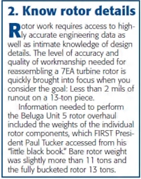
A well-equipped shop and experienced crew are critical to success, Tucker told the editors (Sidebar 2). His resume includes the disassembly and reassembly of more than 1300 rotors over a career which began as an 18-yr-old trainee in a GE shop. The consultant believes that Beluga is capable of handling rotor projects specific to its needs as well as any Houston shop.Why overhaul the rotor onsite? Beluga, about 40 miles due west of Anchorage across Cook Inlet, has no paved-road access and essentially is accessible only by plane (Fig 2) and barge (Fig 3), weather permitting.
Shipping the rotor to Houston for the overhaul would have been very expensive and taken upwards of three months. Chugach had less than a month to complete the project. Anyone who has served in the navy or merchant marine knows what working at Beluga is like. When there are problems to solve and things to fix, it’s up to you to get them done. Crews rotate in and out of the plant on a weekly basis; daily shifts are 12 hours. The staff’s can-do attitude is particularly important because Beluga supplies up to about 40% of the electricity consumed in Southcentral Alaska.
The plant sits on top of a remote gas field. When Beluga was built in the 1960s, there was no energy infrastructure connecting it to Anchorage. Transmission lines were built because low-interest REA money was available for transmission facilities.

The Beluga Frame 7s
The first Beluga 7B, Unit 3, began commercial operation in 1973; the second, Unit 5, began commercial operation in 1975. Unit 3 was upgraded to a 7EA (turbine section only) in 1988 by the plant staff under the direction of an OEM TA. This was the first such conversion by the manufacturer and testing was extensive to evaluate the effects of using a 7E Stage 1 nozzle in a B machine—including the monitoring of compressor performance and startup characteristics.
Favorable results provided the incentive for Chugach to upgrade Unit 5 in 1991. That effort included retrofit of the new E-style combustion system. Note that the OEM offers several options for upgrading Bs to Es. Option 1, as defined in GER-3808C, the alternative selected for Beluga, retains the B firing temperature in the new E configuration. The other options offer progressively higher firing temperatures.
 Conversion from a B to an EA turbine requires change-out of the 1-2 spacer and new buckets and nozzles for the first two stages. Note that an EA has air-cooled buckets in the first- and second-stage wheels, the B has air-cooled buckets only in the first stage.
The EA 1-2 spacer in Fig 4 has 12 air slots for supplying 16th –stage (compressor) air for R1 bucket cooling; the flip side has six slots for supplying cooling air to the R2 buckets. The B 1-2 spacer has six slots for supplying first-stage cooling air on one side, none on the flip side because the second stage buckets are uncooled.
Beluga’s Frame 7s came equipped with regenerators to maximize simple-cycle efficiency; Chugach planned to operate the units for more than 6000 hr/yr. Last year both units ran over 7500 hours each.
The recuperators, prone to leaks, were removed and the inlets/outlets blanked off years ago. In the mid 1990s, Unit 5’s regenerative wrapper was replaced with a standard simple-cycle wrapper with the expectation that the lives of combustion parts would be extended. Plant personnel said that the upgrade did not prove cost-effective and the regenerator combustion wrapper on Unit 3 was not changed-out.
Rotor overhaul: First steps
Most O&M personnel at plants with GE frames are familiar with the first few steps in the rotor overhaul process: Remove the upper casing half, break the marriage coupling, and lift out the turbine and compressor rotors. Fig 5 shows the turbine rotor and load coupling being moved to a support skid on a flatbed (Fig 6) for transport a couple of hundred yards to the Beluga shop (Fig 7).
The compression section was put on supports alongside the package, where it would be cleaned by hand (Fig 8). Maintenance Foreman Ken Knecht, who was responsible for the gas-turbine overhaul the week the editors were onsite, said oil leaks were the biggest source of compressor fouling and that offline washes were done annually.With the rotor accessible on the plant floor, plant personnel would hand clean the airfoils using an effective washroom hand cleaner and wipe them off with rags. Power washers for this work are forbidden at Beluga to keep water out of the wheel joints.The lower half of the casing, rotating parts removed, is shown in Fig 9.
The first step in Tucker’s very detailed procedure for rotor disassembly and reassembly was an as-received inspection. For each of the 31 sequential steps in the Beluga procedure, he provided a description of the work, the personnel skill sets required, the number of people needed, and an estimate of total hours.Example, incoming inspection required two rotor technicians and should be completed in 20 man-hours. The task description on the summary sheet used to chart job progress refers the inspection team to a document that details exactly how the inspection should be conducted, what to look for and where, what to do if you find damage, etc.Several hundred documents, procedures, data forms, check-off/sign-off sheets, are required for a turbine-rotor upgrade project like Beluga’s. You want to have a record of anything and everything that might be needed in the future.
No significant issues identified, the rotor was set up in the balance machine to conduct an incoming balance check and record runouts (Fig 10). Next came gap checks on all rows of buckets, followed by removal of the buckets from the rotor.Careful record-keeping is required during bucket removal. It is important to properly record serial numbers of all buckets and their location in the row. During disassembly, technicians were asked to note any missing shank pins, D-keys, platform pins, and/or anything unusual. Buckets were boxed by row and labeled appropriately.
The Beluga O&M team operates and maintains its gas turbines with a conservative hand. This was reflected in the condition of the wheels and buckets (Fig 11). A visual check of the fir trees revealed no obvious wear and tear. The plant’s innovative turning-gear mod, clean gas, and pristine air likely contributed to the machine’s good health. More detail on the turning-gear enhancement later.
Determination and recording of as-found turbine-bolt stretch was the next task. The experienced crew had a difficult time with the 12 turbine bolts. Despite repeated attempts at removing the nuts with a hydraulic wrench, the only “progress” was broken sockets (Fig 12). Technicians had to drill out all 12 bolts. This had little schedule impact because new bolts had been ordered and were onsite. However, the mindset at Beluga is not to waste anything. Rotor bolts cost about $2500 each.
During attempts to remove the rotor bolts, the editors were introduced to the Beluga backup wrench (Figs 13 and 14) used to prevent turning of the nut on the opposite end of the bolt when the hydraulic wrench is in use. It was designed and made by plant personnel. The level of sophistication of the plant’s technicians is evidenced by the stress analysis to assure the tool would perform as intended.
Next, bearing surfaces were protected against dings and scratches and rotor components were temporarily secured with four rotor bolts so the entire piece could be lifted and put into position for disassembly. The rotor was oriented vertically using the turnover fixture (also made by the plant) that Tucker is standing behind in Fig 15.
The aft stub shaft was bolted to the fixture as shown in Fig 16 and the shop’s 20-ton bridge crane rotated the shaft into the vertical position required (Fig 17). After unbolting the aft flange from the fixture, the rotor was moved to the disassembly area and fastened to the support plate at the bottom of the pit (Fig 18), a safety feature recently added by plant staff to eliminate the need for scaffolding.To facilitate understanding the discussion on disassembly that follows, it’s worthwhile re-familiarizing yourself with key components of the Frame 7 rotor as presented in Fig 19. Important to note is that all three wheels have female rabbets, while the two spacers and forward and aft stub shafts have male rabbets.

Disassembly
This was the third time the Unit 5 turbine rotor would be overhauled by the plant staff since the GT was installed in 1975. Game plan for the 200,000-hr overhaul was to dismantle the rotor and examine the spacers and stub shafts using a combination of conventional inspection and metallurgical examination techniques to determine if the material condition was suitable for continued service.Risse and his engineers in the Power Supply Div already had decided to replace the wheels to assure timely project completion.
The new Cr-Mo-V disks—standard for this engine type—were onsite before the project began (Fig 20). The original wheels could be examined later, and if acceptable for continued operation, refurbished and retained onsite as spares or sold.
The disassembly procedure began by packing the birdbath area of the forward stub shaft with dry ice. The cardboard dam in Fig 21 allowed technicians to achieve this goal. That done, the rotor team preloaded the shop-crane hook to about 3000 lb—a few hundred pounds more than the weight of the forward stub shaft (Sidebar 2).
Tucker said that the fit between the stub shaft and the first-stage wheel was designed for an interference of 4 to 10 mils. The dry ice would shrink the male rabbet on the stub shaft, he continued, and the hook tension would gently separate that piece from the wheel as shown in Fig 22 with an assist from three jacking bolts. This part of the job took only 15 minutes, with Foreman Knecht and Tucker closely following the disassembly process (Fig 23).

Removal of the first-stage wheel required two more Beluga-made tools: the so-called spacer adaptor in Fig 24 and the center bore lifter in Fig 25. The two devices are shown installed in Fig 26. Technicians applied heat to the first-stage wheel to relax the female rabbet fit, thereby enabling the hydraulic pistons on the spacer adaptor to lift the wheel off the 1-2 spacer (refer back to Fig 4). Note that the crane hook is preloaded to 5000 lb, slightly above the weight of the first-stage wheel.
Heat was applied to the wheels “gently” (Fig 27). Two or three technicians moved their torches within 180- to 120-deg arcs to avoid creating hot spots. Tucker responded to a question by the editors regarding the use of a gas ring for heating: “A gas ring creates areas of flame impingement that can damage a wheel, particularly ones made of alloys 706 and 718,” he said. He mentioned one instance where a high-alloy wheel exploded because of severe flame impingement.

The dynamometer was carefully monitored during the disassembly process by Tucker (Fig 28) who shouted out any drop in load of about 100 lb or more. One technician adjusted the chain fall to reset the load on the hook to 5000 lb while three more manned the hydraulic jacks to slowly lift the wheel. The pistons are up about an inch in the photo.
A level lift is extremely important for preventing scoring of the rabbet surfaces. Tucker warned, “If you don’t take your time and ‘follow the metal’ you will gall the fit.” Technicians operating the hydraulic hand pumps continually measured the distance between the spacer and wheel and shouted out the gaps to colleagues so adjustments would level the lift. It took an hour and 20 minutes to remove the first-stage wheel from the 1-2 spacer (Fig 29).
The disk was moved to a cooling-off area (Fig 30) and dismantling continued with dry ice being packed in the spacer to shrink the male rabbet and allow the spacer adaptor to lift it off the second-stage wheel (Fig 31). Removing the 1-2 spacer took two hours. Steps were repeated until just the third-stage wheel and aft stub shaft remained. In Fig 32, a technician takes up on a jacking bolt to lift the third-stage wheel off the stub shaft.
Verifying parts for rotor reassembly
Rotor disassembled, the parts Chugach hoped to requalify for at least another major cycle—the two stub shafts and two spacers—were scheduled for nondestructive examination, metallurgical examination, and cleaning. The new parts—first-, second-, and third-stage wheels, rotor bolts, and nuts—were prepared for dimensional verification.
The stub shafts were moved outside the shop where they were cleaned with a high-pressure mixture of water and environmentally acceptable detergent to remove oil, rust, dirt, etc. Next step was transport to the plant for NDE prior to bead blasting in a special room built by Beluga staff with a removable roof for easy access (Figs 34 and 35). Blast facility can accommodate all of Beluga’s rotors. A special lifting beam was built onsite to facilitate rotor handling (Fig 36).
Glass beads were used for the final cleaning step, after installing a protective cover on critical bearing surfaces. Knecht said aluminum oxide is too aggressive for turbine hot parts. Stub-shaft runout was verified as acceptable prior to metallurgical examination (Fig 37).In parallel with this effort, Don Norsworthy, senior metallurgist, Gas Turbine Materials Associates (GTMA), San Antonio, was back in the shop performing a battery of tests on the spacers (Figs 38-40). Later he performed the same procedures on the stub shafts. Tests to evaluate material health included metallurgical replication, hardness testing, chemical analysis, dimensional measurements, and visual inspection.
GTMA conducted this same series of tests on the Unit 3 rotor when it underwent a 200,000-hr overhaul and evaluation four years ago. Turbine wheels for that engine also were examined and certified for further use. They have been retained as emergency spares.Discussion with Norsworthy and GTMA President Henry Bernstein, PhD, revealed that the company has performed similar metallurgical evaluations with rotors assembled—both in the half shell and on rotor stands. However, Bernstein noted, it is best to evaluate turbine components after rotor disassembly.
Metallurgical replication. Watching Norsworthy, who arrived at the site with a portable metallurgical lab packed in three large trunks, was instructive. He began the metallurgical replication process by grinding and polishing a small spot of the component metal to an optical, mirror finish. Grinding papers used are from 80 to 1200 grit; polishing is done from 9 microns down to 0.05 micron (350 to 2 micro-inches) using specialized equipment.
After polishing, the spot is etched in alloy-specific acids to reveal the structure of the metal. This “signature” is recorded by using a thin, acetate tape and a solvent applied to the etched spot. The tape captures a mirror image of the metal’s structure, referred to as a replica.
After drying, Norsworthy removed the tape, put it on a slide, and examined the replica at up to 1000× magnification using a portable field microscope. With this capability, an initial evaluation of the metallurgical condition of the rotor was immediately provided to Chugach. GTMA verified the field results on its laboratory microscope. If necessary, it can examine the metallurgical structure up to 35,000× magnification on the company’s scanning electron microscope (SEM).

Hardness testing provides another measure of the metallurgical condition of the rotor. Norsworthy had multiple portable hardness testers in his “road lab.” The one selected depends on the component being examined.Chemical analysis of the base metal is performed to ensure that the correct alloy is being used, which doesn’t always occur. In addition, any deposits of concern are collected and analyzed using GTMA’s energy dispersive spectroscopy (EDS) system mounted on the company’s SEM.
Norsworthy then made dimensional measurements and compared them to information on the component retained in GTMA’s database of rotor inspections. Bernstein said GTMA has been performing rotor assessments since 2000 and has compiled the largest such independent database in the industry.
Results. Considering the test results, Unit 5’s operational history, and GTMA’s past experience with engines of the same type as Beluga’s, Norsworthy and Bernstein found that the stub shafts and spacers were in acceptable condition to operate for an additional 100,000 hours. GTMA had provided the same report card on the Unit 3 rotor four years earlier.
Dimensional verification. Having confirmed that all components—both new and those being reused—were inherently suitable for rebuilding the rotor, detailed dimensional checks were required to assure that all parts would go together as intended (Figs 41-43). Here’s a list of several required tasks:
- Measure and record the rabbet fits of all components to verify they are within the interference range of from 4 to 10 mils.
- Conduct a bucket-gap check on the new wheels to be sure no gap or fit-up issue exists. Also important: Record the axial movement of Stage 1 buckets using a new “D” key.Recall that the “D” key is an axial lock that prevents migration of the bucket in the wheel slot. A twist lock is used to accomplish the same goal for second- and third-stage wheels.
- Verify that nuts run up on all the new studs; disable the locking feature.n Check the new turbine bolts to be mils.n Verify bolt-hole position and dimensions are accurate for the three wheels. When asked why this was being done considering the wheels were manufactured by the OEM, Knecht responded, “We’re not like anyone else. We do everything possible to assure success.”
- Record runout readings taken on all wheels and spacers on the runout stand (Fig 41) and those for the stub shafts (top mating flange and journal) taken on the VBM (refer back to Fig 37. This information was given to Tucker who used a proprietary computer program to orient the parts so the assembled rotor achieved its runout goal of less than 2 mils.
- To illustrate how precise the parts must be, Tucker said that any rabbet runout, or face runout, that exceeds seven tenths (0.0007 in.) must be repaired.
Reassembly
The Unit 5 rotor was reassembled aft forward. The aft stub was positioned in the assembly pit and through-bolts were installed. Aft end plugs were inserted in the studs prior to stacking, beginning with the third-stage wheel (Fig 44).Restacking proceeded according to the computer-generated plan noted earlier. Success, Tucker said, requires you to heat the wheel in the shop oven to get the correct rabbet fit, but not so hot that you throw the bolt circle out of whack and can’t drop the wheel down over the bolts. Achieving these dual objectives typically requires a temperature differential between the spacer and wheel of about 200 deg F.
Sequence of photos (Figs 45-47) illustrates the restacking procedure. After the stack was normalized, bolts were torqued to 100 ft-lb in the stretching order specified by Tucker. The required bolt elongation for Beluga 5’s turbine rotor was 53 to 56 mils. The TA recommended two stretches—the first one 30 mils—to achieve the elongation specified.
The completed rotor then was moved to the balance machine (Figs 48 and 49). Tucker provided balancing criteria and procedures, and forms for proper record-keeping. Second-stage buckets were installed first, then balance check; third-stage buckets next and another balance check; first-stage buckets last and yet another balance check (Figs 50-53). Final quality checks, inspection, and sign-off by the foreman and TA were the final action items in the procedure.
Stationary parts
While rotor work was pursued in the shop, reconditioned nozzles and shroud blocks were being installed in the turbine casing back in the plant. Laydown space was provided for the upper half of the casing alongside the Unit 5 package. Beluga has at least one spare set of qualified nozzles available in the plant storeroom at all times.
Airfoils are not repaired at Beluga, but shroud blocks are, saving more than half the cost of new parts. When the units are running, there’s time available for the maintenance team to recondition certain parts and make some new ones as well.Shroud blocks typically are repaired every 50,000 hours (Fig 54). Plant personnel grind out cracks and machine about 30 mils off the face of the blocks. Then the cracks are weld-repaired and the shroud face built up with weld metal. Stress relief (Fig 55), final machining (Fig 56), and dimensional checks (Fig 57) came next. Job complete, the resurfaced shroud blocks were sent to a shop qualified for coating with an abradable material and then reinstalled (Fig 58). Coatings are one of the few things the Beluga staff does not do—not because it can’t, but because it’s uneconomical at the present time.Picture frames. The maintenance team also makes picture frames for the Frame 7 transition pieces (TPs). Foreman Knecht said the original frames were made of cast Hastelloy® X Alloy and had floating seals. They only were good for about 3000 hours of service.
Today, the picture frames are made of Nimonic® Alloy 263 by Beluga personnel (Figs 59-61) and floating seals of a new design are purchased from a third-party supplier. The new hardware already has accumulated more than 5000 hours in one engine and the plan is to inspect floating seals at 6000 hours.
Substandard seals will be replaced and the transition pieces scheduled for another 6000 hours of service. When the 12,000-hr service run is complete, the TPs would be sent out to a qualified shop for standard overhaul—including refurbishment of wear guards, installation of new seals, and recoating.When picture frames must be replaced, the TPs and Beluga-made frames are sent to a shop where the old frames are cut off and new ones are welded in place (Fig 62).

On being proactive
The concept of end-of-rotor-life at an arbitrary number of hours (the way the OEM wants to count them) or given number of starts (also the way the OEM wants to count them) runs counter to conventional logic. Mechanical and electrical components—like people—don’t simply become “no good” at a given point in time—they degrade over time, some faster than others.
As an owner of a gas turbine, doesn’t it make more sense to monitor the condition of your equipment over its operating lifetime rather than just once at end of life? Benefits include identifying deterioration before the onset of failure; planning earlier for component replacements, repairs, and upgrades; changing operating procedures to reduce wear and tear and extend maintenance intervals; maintaining a record of machine health to better predict when to retire parts, etc.
The overwhelming majority of owners surely subscribe to this thinking, which is why today’s units have sophisticated monitoring equipment and control systems to minimize the “stress” on their engines. But what about issues online diagnostics may not identify until it’s too late to do anything but take a forced outage?
An engine teardown, such as the one described here for Beluga, might be beneficial doing at each major, according to FIRST’s President Tucker. One reason is that any birth defects would be identified early in life and could be tracked over the years.
If the defect does not grow over the unit’s service life, it would not be a reason to condemn the rotor when it reaches the OEM’s lifetime limits. However, if the first time you identify the defect is at the manufacturer’s hours or starts limit you don’t know if it’s something to be concerned about or not.
Tucker suggested a remaining life analysis at each major for all rotor components except bolting and stub shafts. The rotor expert’s comments were based his extensive experience with GE Frames 3, 5, 6B, and 7B-EA. Some tweaking would be necessary for other models.For example, he suggested magnetic particle examination to identify surface defects on rotor components for the GE engines identified above. This would not be possible for all gas turbines because of materials differences. Liquid penetrant would be used where mag particle does not apply.
Half of the inspection time, Tucker estimated, would be expended on a boresonic (volumetric) inspection to identify sub-surface flaws. In addition, eddy current would be used to check for creep, metallurgical replicas for grain-boundary issues, hardness for metallurgical changes. Finally, all physical dimensions would be verified against original drawings.Additionally, Tucker continued, the compressor rotor also should be involved in any remaining-life survey—in particular the last four rows, which are the hottest.
He said that a conservative cost estimate for a Frame 7 disassembly, rotor unstack, end-of-life inspection, rotor re-stack, and unit reassembly is approximately $700,000. Typically, a week is all that’s required to complete the entire scope of work. Schedule and cost estimates assume a clean bill of health.
Turning gear. In late spring and early summer the night is always “young” in Alaska and Tucker segued into a discussion on turning gear. For peaking machines and GTs supplying ancillary services to the grid that require full power within 10 minutes of being called, he said, end of wheel life sometimes occurs long before the OEM’s starts limits are reached.
Dovetail wear caused by long-term turning gear operation is chewing up wheels at many plants, Tucker said, mentioning three utilities that were changing out 7B wheels fleet-wide—engines averaging 100 starts and 500 hours annually. “Do the numbers,” he challenged. “In 25 to 30 years, which is the average age of these machines, they’re only about halfway to the starts limit, yet the wheels are shot. Shrouds on R2 and R3 buckets are taking a beating as well.”
The consultant was referring to the 6-rpm turning-gear systems found on many of the older frames in the GE fleet. He said that wheelspace temperature typically controls motor shutoff and if the setting is too low, an engine can be on turning gear for days—until a timer shuts it off. For the 100-annual-starts/500-hours example above, this means it’s conceivable for a unit to be on TG all the time it is not operating.
It’s difficult to visualize the damage being caused by excessive TG operation, but it’s easy to listen to what’s happening and gauge from that. Take a minute to access www.ccj-online.com/tgmod and listen to the videos monitoring turning-gear operation at 0.5 rpm and at 6 rpm. The latter reveals continual pounding of metal, the former virtually none.
Tucker questioned why operators would want their engines on gear until the wheelspace temperature drops to 100F, or ambient temperature. He believes 200F-220F is fine. Of course, the wear-and-tear problem disappears if you’re buying a new unit and specify a ratchet for turning-gear service.
The cost of wheel and shroud damage is significant. For example, shroud repairs on R2 and R3 of a 7B can run about $40,000. Coating fir trees to eliminate bucket rock typically runs about $50,000. But both fixes are short-lived unless you correct the root-cause of the wear. Tucker offered three alternatives:
- The least expensive solution is to optimize time on turning gear to reduce wear.
- Convert to a ratchet system. Cost is about $500,000.
- Install FIRST’s RPM Reduction Modification for GTs equipped with ac or dc electric-motor-driven continuous turning-gear systems. It allows turning-gear operation at any speed between 0.33 and 6 rpm. Cost is about $40,000. System comes equipped with a hand control pendant to permit independent control of rotor position during alignment checks, borescope activities, bucket removal/installation, and the marriage/mating of rotor couplings during outages.
A TG mod similar to that offered commercially by FIRST has been operating at Beluga for five years with excellent results. Chugach’s Knecht said just slowing TG speed to 3 rpm has had a very positive benefit. You can listen to Knecht’s own words at the link provided above. Another benefit of eliminating bucket rock is that sealing pins, which prevent combustion gases from leaking into the wheelspace area and overheating the disks, will not liberate and go downstream and cause damage. ccj
4. At Beluga, success is spelled people
FIRST President Paul Tucker knows what it takes to disassemble and reassemble a gas turbine rotor—he’s done it more than 1300 times in his career. That makes him an expert. Tucker told the editors, “It’s all about people and the equipment.” Skilled tradesmen guided by knowledgeable supervisors are critical to success, he said. Desire is a necessary attribute for all involved.
As for facilities, Tucker mentioned big lathe, suitable crane, balance machine, and special fixturing as the basics. An impromptu audit of the Beluga shop by the editors included the following: 20-ton bridge crane, an IRD balance machine that also can be used for machining rotors, several lathes, radial arm drill, tool sharpeners, grinding wheels, grit blaster, heat-treat furnace, saws, hydraulic presses, many special fixtures and tooling, sophisticated measurement instruments, computers and software for mechanical design and information storage.
Beluga has two complete O&M teams that work a week on/week off and both participated in the rotor life-extension project. When the editors were at the plant, the Blue crew (photo) was onsite.The Blue crew’s maintenance team foreman is Ken Knecht a trained millwright who grew up in Alaska and was a contract employee at several plants before being selected to participate in the installation of Units 7 and 8 (the ABB gas turbines) at Beluga. He hired on at Chugach Electric Assn Inc in 1980 as a maintenance technician based in Anchorage.
A few years later he was assigned to Beluga and has been there since.Each shift team put together for the Unit 5 rotor life-extension project incorporated six maintenance technicians (three of them temporary hires), a machinist, welder, plant helper, heavy-vehicle mechanic, and maintenance helper. Both crews are supervised by Maintenance Supervisor Scott Jeffryes.Proof of the valuable learning experience that comes from working at the remote plant can be found in the leadership of some of the industry’s top gas-turbine users groups. A couple of names that come to mind are Raymond Martens, currently managing director of Klamath (Ore) Cogeneration and Peakers for Iberdrola Renewables, and Joe Schneider, the Siemens gas turbine specialist for GenOn (recently formed by the merger of Mirant and Reliant).
Martens was the Beluga plant superintendent for nearly nine years. While a Chugach employee he was a member of the ABB Gas Turbine Users Group steering committee, chairing it for three years. Since coming to Klamath, he has served on the CTOTF Leadership Committee and on the 501F Users Group steering committee. He currently is associate chairman of the latter.
Martens recalled the challenges associated with the need for high reliability at Beluga because the plant supplied about half the power used in the southcentral part of the state. That, plus the demands associated with operating a generating facility at a remote site required the staff to be very innovative, he said.Martens noted that while he was there, the first-class barracks and food service facility now in use was built. He also participated in the early stages of the Alstom upgrades to 11DM and the upgrade of the GT control systems. Risse was the project manager for the balance of the upgrades.
Schneider joined Chugach in 1986 as the maintenance supervisor for a roving crew that overhauled remote hydro units. He moved to Beluga as a maintenance supervisor three years later and remained there through 1993.Schneider recalled the “can-do” attitude of plant personnel and Beluga’s shop capabilities. Three jobs that stand out in his mind 15 years later was the unstacking/restacking of a 7B rotor, weld repairs to the 11D4A, and onsite compressor coating accomplished by Sermatech’s mobile team working with plant personnel. Like Martens, Schneider recalled the relentless drive for top reliability.
To illustrate the plant’s importance in southern Alaska, he remembered one winter night when the gas supplier lost pressure and the plant tripped, turning off lights from the southern-most point on the Kenai Peninsula (about 100 miles south of Anchorage) north to Fairbanks.
From 1993 to 1999, Schneider was the company’s “plant engineer,” responsible for planning, scheduling, PM, and PdM. Today, he is the chairman of the Siemens Roundtable for CTOTF.
