


The first major user group meetings of 2014, the 501F and 501G, are coming up fast. Both conferences will run concurrently from Sunday, February 16, through Thursday, February 20, at the Westin Mission Hills Resort & Spa in Rancho Mirage, Calif. The two groups will come together for discussions on issues of mutual interest, vendor fair, meals, and social events. About 200 owner/operators are expected to attend the annual event.
Russ Snyder and Steve Bates, who chair the 501F and 501G steering committees (Sidebar 1), respectively, shared conference highlights with the editors (Sidebar 2) to facilitate your planning. For updates, visit the websites of both users groups: http://501F.users-groups.com and http://501G.users-groups.com.
If you have not been to a 501F/501G meeting in the last few years, explanation of the term “vendorama” in the conference highlights might be beneficial. The steering committees invite technical presentations by third-party equipment and services providers serving the 501F and 501G fleets on Day One of the meeting. These presentations are vetted by the committees to assure content of value to owner/operators and to eliminate any promotional material.
The presentations program, which begins 10:30 am Monday, February 17, and ends about an hour before the vendor fair and reception at 5:15, is called “vendorama.” Attendees receive schedule grid onsite. Last year, there were six concurrent presentations in each of the eight half-hour time slots. Typically, prepared remarks run 15-20 minutes and Q&A up to about 10 minutes. At least one steering-committee member attends each session to assure a timely start and end to the proceedings.
| 501F Chairman: Russ Snyder, plant manager, Acadia Power Station, Cleco Power LLC
Vice Chairman: Ray Martens, plant manager, Klamath Cogeneration Plant, Iberdrola Renewables LLC Vice Chairman: Ivan Kush, director of technical services, Calpine Corp Rene Villafuerte, plant manager, CCC Saltillo, Falcon Group |
501G Chairman: Steven Bates, plant manager, Wise County Power Co LLC, GDF Suez Energy Generation NA Inc
Scott Wiley, fleet maintenance manager, GDF Suez Energy Generation NA Inc |
Exhaust systems
The value of user groups to gas-turbine owner/operators cannot be overstated. It is highly doubtful that this sector of the electric power industry would have matured so quickly had user groups not been formed years ago to help owner/operators share experiences, best practices, lessons learned, spare parts, etc. The all-volunteer user groups also have contributed significantly by collaborating with OEMs on behalf of owner/operators to help resolve fleet issues.
There are many specific examples of how user groups have contributed to the improvement of simple- and combined-cycle plants over the years. One that stands out in the 501F fleet is the exhaust system. The service histories of most, if not all, exhaust systems serving F-class and more advanced engines indicate the challenges posed by high gas temperatures and velocities, the need to cycle gas turbines more frequently than was anticipated at the design stage, and the desire to use the least costly materials available.
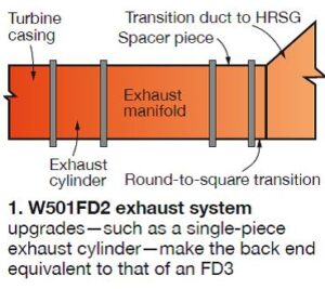 The 501F users began sharing experiences on the repair of cracks in exhaust manifolds, exhaust cylinders, and struts years ago (Fig 1). It was a lively topic at most meetings because virtually every repair that promised to be the “repair to end all repairs” never did—unrealistic expectations perhaps. A couple of users told the editors they had given up on ever having a permanent repair and had welders on call for annual outages to patch the system to the extent possible.
Examples of the extensive and detailed coverage given exhaust-system repair methods at the 2008 and 2009 meetings illustrate the collaborative mindset nurtured by the industry’s user groups.
While the users were investigating various repair techniques to resolve exhaust-system problems at least cost, the OEM was designing replacement systems to accommodate the operational realities of the day. Replacement alternatives for owners of 501FA, 501FC, and 501FD2 engines are the advanced two-piece (ATP) and single-piece exhaust (SPEX) systems.
The former (Fig 2) was developed as a drop-in replacement to address durability concerns with the original two-piece design. This is termed a “thermally compliant design” featuring materials upgrades and more robust cylinder cooling to reduce creep concerns. The first commercial installation of the ATP was completed in May 2012 during a major inspection outage. That exhaust system, heavily instrumented, has been running in base-load service since with data revealing no issues and suggesting engineering expectations are being met.

The SPEX, or single-piece exhaust, is of a thermally unconstrained design and specified as original equipment for F4 and F5 machines; some new FD3s were provided with it as well. It also can be retrofitted in place of the original two-piece exhaust on earlier models (Fig 3). More than three dozen SPEX systems are in operation, with the fleet leader in the neighborhood of 30,000 equivalent base-load hours. The OEM reported positive user experiences with the new system and showed a large number of complimentary photos taken during inspections.
Retrofitting SPEX to one of the early 501s is not a decision to be made quickly. There’s a great deal of work involved in such a project, but some of the cost can be offset by upgrading R4 of the turbine at the same time and taking advantage of performance improvements.
Klamath Cogeneration Plant was a pioneer in transitioning from the original two-piece exhaust cylinder to the SPEX/R4. Plant Manager Ray Martens, a vice chairman of the 501F Users Group, and his staff believed the single-piece exhaust cylinder offered a long-term maintenance advantage. Martens gave attendees a detailed description of the exhaust-system replacement and the accompanying performance upgrade project at the 501F meeting a few years ago.
With well over 100 engines in the 501F fleet as potential candidates for exhaust-system upgrades, interest in this topic remains high. At last year’s meeting a user addressed the group on his plant’s experience. It began in fall 2010 when three cracked struts were repaired by the OEM, which provided a one-year warranty. Strut inspections were required every five starts. During one of those inspections, in January 2011, engineers found cracks in the exhaust manifold’s outer diffuser had begun to separate and grow (Fig 4). Repairs were scheduled for the fall.

During a phased-array ultrasonic inspection in June, a 6 in. crack was found in one of the struts (Fig 5). Over the next month the crack grew by 2 in. and the unit was takenout of service. The OEM repaired the strut, but it warped during post-weld heat treatment and the back end of the unit sagged; it could not be realigned. The speaker said the plant considered these three options:
- Replacement in kind with a pre-owned exhaust system.
- Retrofit with SPEX.
- Retrofit with ATP.
Plant personnel viewed SPEX positively for its (1) availability (six-month delivery), (2) upgraded manifold and cylinder design and materials, and (3) potential for future thermal performance upgrades. Negatives included unknown performance without doing the thermal performance upgrades that Klamath did, as well as limited room for installation.
ATP presented no clearance constraints and also offered upgraded materials. However, there would be no operating experience with this design until mid-2012 at the earliest (serial No. 1 was scheduled for installation in spring 2012) and costs were not much different than SPEX. Also, this arrangement does nothing to improve exhaust-manifold materials issues and questions remained in the minds of plant personnel regarding dead-air-space cooling and venting.
In December 2011, following field inspection of manufacturing facilities, a SPEX was ordered for June 2012 delivery. The plant outage began in April with engine disassembly and replacement of necessary components. The exhaust manifold and cylinder were removed and scrapped. Generator was rewound.
Among the lessons learned:
- Purchase applicable tooling for SPEX installation.
- Buy extra bolting, Nord-Lock washers, and nuts for the bearing tunnel.
- Order radial vibration and blade-path thermocouples. They are different than for the original exhaust system and lead times are long.
- Install bearing lift oil system.
- Follow manufacture of the SPEX carefully. This user found defects in strut shields and surface issues with new struts.
- Pay attention to the trapeze-spring can setting. Trapeze changes startup and shutdown characteristics; it does not dampen as well as the previous design.
- Flow changes from SPEX caused several new hot spots on ductwork to the heat-recovery steam generator.
- Existing fire protection system likely requires upgrades to accommodate the new bearing tunnel. An engineering and fire-code review effort is recommended.
The exhaust system likely will be introduced as a discussion topic at the 2014 meeting. If you are considering an upgrade and have questions, bring them to the meeting. Several colleagues in attendance will have experiences to share; plus, Siemens engineers will be available.
Thru-bolt fracture
Another hot topic for the California conference will be the compressor thru-bolt issue on 501F models earlier than the SGT6-5000F(4). The OEM is currently discussing with customers changes coming for the bolt, the nut, and the disc. Be there to get the latest information first-hand. If you’re a 501F (SGT6-5000F) owner/operator and not aware of this issue, you probably have not been attending user group meetings or reading OEM advisories. Most likely, you’re new to Siemens engines. A quick summary to bring you up to date:
- One compressor thru bolt fractured on each of two gas turbines in this family of engines in 2012—six months apart. An indication was found in a third bolt during the inspection and destack of one of the two units with fractured bolts. Note that only those compressors designed with 12 thru bolts are of interest. The latest machines, models designated SGT6-5000F(4), (5), and (5ee) have only one bolt and are not pertinent to this discussion. The failures occurred in the threaded portions of the bolts between the R2 and R3 compressor blades as shown in Fig 6.
- The fractures were identified at two different operating conditions—one on load ramp, the other on turning gear. Flow-path damage was experienced on one machine. Each of the engines had accumulated more than 40,000 equivalent base-load hours and about 2500 equivalent starts at the time of their respective incidents.
- User discussions suggest crack initiation is at the first loaded thread and that a small flaw propagates quickly on such highly loaded bolts. One estimate is that failure can occur in only 300 hours after crack initiation. More detail: Thru-bolt nuts shift radially outward during starts, increasing the loading on threads at bottom dead center. High-cycle fatigue (HCF) damage accumulates during starts. Other possible influences on crack initiation may be one or more of the following: duty cycle, rotor configuration, assembly variation, and variations in material properties, among others.
- Investigation of the events continues. The OEM is conducting, for data-gathering purposes, opportunistic conventional UT inspections of compressor bolts at major inspections or any outage requiring a compressor-cover lift. Recommendation: Replace compressor thru-bolts and nuts following a compressor de-stack.
2. 501F and G meeting highlights
Sunday, February 16:
Morning
11:15, Sign in for the golf tournament
Afternoon
12:30, Tee-off
5:00 to 8, Welcome reception
Monday, February 17:
Morning
7:00, Registration
7:00, Breakfast
8:30, Welcome and introductions, F and G users, closed session
9:00, Safety roundtable, F and G users, closed session
10:00, Morning break
10:30 to 12:10 pm, Vendorama, F and G users
Afternoon
12:10 to 1:05, Lunch
1:05 to 2:15, Vendorama, F and G users
2:15 to 2:35, Afternoon break
2:35 to 4:10, Vendorama, F and G users
5:30 to 9:30, Vendor fair and reception
Tuesday, February 18
Morning
7:00, Breakfast
8:00 to noon, Siemens presentations for F users; closed session for G users
10:15 to 10:30, Morning break
Afternoon
Noon to 1:00, Lunch
1:00 to 5:00, Siemens presentations for F users; closed session for G users
2:30 to 3:00, Afternoon break
Evening
5:30 to 9:30, Siemens Event
Wednesday, February 19
F Users Program
Morning
7:00, Breakfast
8:00 to 9:30, Mitsubishi presentation
9:30 to 10:15, Inlet and exhaust roundtable
10:15 to 10:30, Morning break
10:30 to 11:15, Auxiliaries roundtable
11:15 to 12:15, Compressor roundtable
Afternoon
12:15 to 1:00, Lunch
1:00 to 2:00, Combustor roundtable
2:00 to 3:00, Hot gas section roundtable
3:00 to 3:15, Afternoon break
3:15 to 4:15, Rotor and casings roundtable
4:15 to 5:15, Generator roundtable
Evening
6:00 to 9:30, Mitsubishi Event
Wednesday, February 19
G Users Program
Morning
7:00, Breakfast
8:00 to 12:15, Siemens presentations
10:15 to 10:30, Morning break
Afternoon
12:15 to 1:00, Lunch
1:00 to 5:30, Siemens presentations
3:00 to 3:15, Afternoon break
Evening
6:00 to 9:30, Mitsubishi event
Thursday, February 20
F Users Program
Morning
7:00, Breakfast
8:00 to 9:00, Siemens Day review and critique
9:00 to 10:00, Steering committee feedback with F users
10:00 to 10:15, Morning break
10:15 to 11:15, Siemens session with F4 users
11:15 to 12:15, Mods and upgrades
Afternoon
12:15 to 1:15, Lunch
1:30 to 2:45, Siemens steam turbine session for F and G users
2:45 to 3:00, Afternoon break
3:00 to 4:00, Steering committee closing meeting
4:00 to 5:00, Steering committee meeting with Siemens executive panel
Thursday, February 20
G Users Program
Morning
7:00, Breakfast
8:00 to 10:00, Closed session
10:00 to 10:15, Morning break
10:15 to 12:15, Closed session
Afternoon
12:15 to 1:15, Lunch
1:30 to 2:45, Siemens steam turbine session for F and G users
2:45 to 3:00, Afternoon break
3:00 to 5:00, Closed session

Starting reliability
Siemens reported that the starting reliability of its F fleet has increased by more than one percent in the last few years (Fig 7), most of that improvement the result of hardware and software changes to the engine’s controls and fuels systems. Starting reliability continued to improve during 2013.

The software mods contributed to the reliability improvement by maximizing the ignition window, reducing startup gas-path temperatures, providing consistent cross-ignition, and minimizing the need for seasonal tuning. Regarding hardware, eliminating some regulator valves and maintaining constant mass flow with changing fuel-gas conditions have contributed to a reduction in maintenance and an improvement in starting reliability for units that restart with hot fuel. A new witch-hat strainer for all DLN fuel-gas stages has contributed to the reliability improvement by protecting fuel nozzles while being less susceptible to clogging.
The takeaway from this OEM presentation: If your starting reliability is not at least 95%, you can do better simply by implementing a few software and hardware changes.
Debris mitigation
You wouldn’t think that the accumulation of a little debris in the seal pin slots of R1 turbine blades would cause blade failures, but it did. The original configuration of the seal slot, at left in Fig 8, allowed debris to accumulate there and form a hard-pack which could cause seal pin-to-platform lock-up. This had a negative impact on blade frequency and allowed the initiation of an HCF fracture near the base of the airfoil. The slot back wall was reconfigured, as shown in the right-hand sketch, with positive results: There have been no R1 blade failures where this solution has been implemented.

Aftermarket competition
The annual meetings of the 501F and 501G Users Groups are among the best industry events for conducting due diligence on engine parts, services, and upgrades, and for purchasing decision-making. The reason is simple: Two major OEMs, Siemens Energy Inc and Mitsubishi Power Systems Americas Inc (MPSA), participate and compete head-to-head to serve a global fleet of about 450 F-class engines. Both manufacturers get significant podium time at the conference and by listening carefully to each you can decide on questions to ask the other. No machine is perfect and competitors generally are willing to share what they believe is wrong with the other company’s equipment.
PSM also is highly visible at the meeting, offering both parts and services for the F fleet. The leading third-party repair shops are there as well—including ACT Independent Turbo Services, Allied Power Group, and Sulzer Turbo Services—competing against the OEMs and PSM. The competitive battle focuses on business associated with the early 501F models—up to and including the 501FD2.
The Mitsubishi team annually updates attendees on the company’s infrastructure and capabilities before discussing the specific modifications and upgrades it recommends to improve durability, reliability, availability, etc, of the 501F engine. At the 2013 meeting, the first slide traced the company’s North American commitment from 2001 ($40 million, seven employees) through 2012 ($550 million, 1700 employees). Facilities installed during that period included the Outage and Resource Center in Houston, Power Generation Services in Orlando, MPSA Headquarters in Lake Mary, Fla, and the Savannah Machinery Works in Georgia. Profiles of each are available online.
Milestones in the development of the 501F was another segment of the presentation and of particular interest to industry newcomers. Here are the highlights:
- 1984. Mitsubishi and Westinghouse Electric Corp agree to co-develop the 501F with a 1350C (2462F) firing temperature.
- 1985. Mitsubishi takes over the manufacture of large gas turbines for Westinghouse, which later closes its Lester (Pa) GT manufacturing facility.
- 1993. First 501Fs begin commercial operation at Florida Power & Light Co’s Lauderdale Generating Station.
 1998. Siemens acquires Westinghouse and the technology alliance between Westinghouse and Mitsubishi is terminated. Mitsubishi begins implementation of materials changes, structural modifications, and cooling enhancements to improve component durability at high firing temperatures.
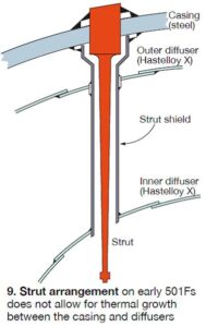
The upgraded parts developed by Mitsubishi were installed in its M501F3 and later offered for the W501FD2. Company engineers presenting at the 2013 meeting focused first on the exhaust system issues experienced by many owner/operators in the room—such as cracking of the outer diffuser, strut shields, and struts. They believe at least some of the cracking can be traced to the design of the strut shield, which is welded to the casing, inner diffuser, and outer diffuser—and does not allow for thermal growth between the casing and diffusers (Fig 9).
The Mitsubishi speakers also pointed to the relatively sharp weld connections at the intersection of inner and outer diffusers and the strut shield, suggesting that smooth fillets would have been a better choice. Regarding materials, it was said that after the two OEMs went their separate ways, Westinghouse embraced the use of Hastelloy X for its outer and inner diffusers. One of its advantages was ease of welding. However, that material becomes brittle with age at F-class GT temperatures.
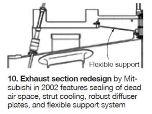
Mitsubishi stayed with stainless steel for the exhaust diffuser and increased its thickness in 2002. Plus, the flexible support system (strut shield is welded to the outer diffuser, not the casing, as shown in Fig 10), sealing off of the dead air space, and active cooling of the struts (an advancement based on G-fleet experience) all contributed to exhaust-system reliability and durability.
Modifications to the M501F two-piece exhaust cylinder to allow its use in W501F gas turbines were underway at the time of the last meeting with expectations that the first unit would be delivered in fall 2013. The Mitsubishi two-piece exhaust can be retrofitted into a Westinghouse machine during a typical major inspection plus three days.
Significant presentation time was devoted to the design features of individual 501F components developed by Mitsubishi that can be used in Siemens engines. Example: Mitsubishi uses assembled-type diaphragms rather than welded. Advantage is that mechanical fasteners increase vibration damping. First use was 1999, now well over 2 million hours of operating experience. Thicker airfoils were first used in a W501FD2 in 2008 in Rows 1-3 to increase structural rigidity; in 2010, in Rows 4-6. No evidence of hookfit wear has been identified to date. Come to Rancho Mirage and get an update.
Among the other components discussed were the following:
- Hybrid DLN combustor baskets, rated for 24,000 hours. The K-point DLN combustor was re-engineered; enhanced swirler mounting avoids swirler pin cracking. Ongoing work includes increasing flashback margin.
- Thick-wall transition piece introduced in 2002, now capable of 24,000-hr intervals. Increase in wall thickness and other design improvements reduced metal temperature and stress.
- R1 turbine blades. Changed material to directionally solidified MGA-1400, enhanced cooling to reduce oxidation loss, modified tip design. Looking to go beyond 50,000 hours.
- R2 turbine blades. Optimized cooling to reduce thermal fatigue, reduced stress concentration of cooling holes, increased fillet radius and trailing-edge thickness in platform, and new material all implemented in 2004 and meeting expectations.
- Turbine vanes. Moved away from cobalt-based alloy and Rows 1-3 now made from MGA-2400, which was said to have 100 times the creep strength of X-45. Also, cooling air optimized for R1.
- Root springs for use under R4 turbine blades eliminate blade rock in W501FC and FD2 units. Work continues on the development of a spring for R3.
You can’t be too safe
The 501G Users Group, chaired by Plant Manager Steve Bates, GDF Suez-Wise County Power Co LLC, is a close-knit organization. Unlike most other user groups, it has a low percentage of first-timers. Almost everyone in the meeting room either knows most everyone else present or knows someone from his or her plant. Another factoid that sets the 501G users apart from the pack: Each plant in the fleet sends an average of two or three employees to the meeting. Most other groups average about one or less.
At the last meeting, the safety discussion, led by Bates, was robust and beneficial to virtually all plants powered by gas turbines. Here are some of the takeaways:
- Scaffold up as the outage progresses. Be aware that protection can be momentary, because as you progress in the outage, railings, etc, have to be added.
- Install a cabling system for tie-offs; it’s tough to design a system flexible enough to accommodate several different engines and plant arrangements.
- Bear in mind that falls of even less than 6 ft can be lethal according to OSHA stats. Wearing a harness is a risk in itself because it can get tangled up, as can the tie line. Plus, workers can get tangled up in other’s lines.
Have a scaffolding crew onsite while work is ongoing, to provide safe access as the need arises. To keep the scaffolding crew busy, use them as part-time helpers to clean bolts, etc.
- Always look to make the scaffolding and fall protection better as the outage proceeds; be sure to take pictures and notes on what works/what doesn’t to make the next outage safer. Verify that tie-offs to beams and piping are rated for the shock load. One user installed a supplemental beam system with full-column support to ground just for tie-offs.
- If you pull a harness from a bin, it must be certified before each use. If you issue harnesses to individuals, as most plants do, annual inspection and documentation is satisfactory. Identify harnesses by their serial numbers.
- Fire watch. The insurance company for at least one user requires a three-hour fire watch (periodic inspection) after hot work. Users agreed that they generally do it for 30 minutes, but for that duty, there’s a watchman with no other duties except fire watch.
- Enclosure test for CO2. If you lift the roof to check for proper sealing, run a fan test. Tough to pass the first time; the second time you do a better job of fit-up and sealing. A CO2 dump test can cost upwards of $50,000, so most do not want to do that. Another suggestion: Put cameras in the enclosure to see if there’s a fire inside before you enter.
- Evap-cooler doors can be difficult to open when need be. A pressure drop of 3 in. H2O can be challenging. You can get that if a fog bank passes or if snow fouls the head end. Consider installing windows in the evap-cooler section so you can see what’s going on in case you can’t get inside. Also, put big grips on the doors because the standard chrome handle may not give you the necessary leverage. And be sure to install hold-open kick latches at the bottom of the doors.
- Confined space. Hire the local fire department for confined-space rescue standby when a plant is more than about 10 minutes away from emergency response personnel. Two benefits: Helps familiarize fire-department personnel with the plant and provides the FD another source of revenue.
- Every time job requirements change, reverify lock-out/tag-out requirements. CCJ