


Leak-testing gas turbines with helium

Challenge. The Nuevo Pemex cogeneration facility in the state of Tabasco, Mexico, is equipped with two 7FA gas turbines, each coupled to a single-pressure HRSG. In cogeneration mode, the plant generates 277 MW and 1.76 million lb/hr of steam.
Maintaining the performance of gas turbines in accordance with OEM specifications, as well as in line with estimated life-cycle degradation, is vital for proper plant operation. Scheduling regular maintenance to identify and repair air leaks in the air intake duct prevents compressor fouling, erosion effects, and deposits on the compressor rotor—all of which degrade performance.
Leaks can be traced to defective expansion joints or manhole seals, defective welds, and faulty component assembly. Several household items can be used to test informally for vacuum leaks—including tissue paper, plastic wrap, soap foam, smoke and shaving cream. However, the following methods deliver more precise, quantifiable results:
- Ultrasonic measurement (UT).
- Vacuum decay test or pressure rise test.
- Helium sniff.
- Helium spray.
Each of these alternatives has its pros and cons. For example, ultrasonic emits a sound that can be higher or lower, depending on the size and frequency of the leak. Very small leaks emit a high-frequency sound that humans can’t hear. This method is not reliable in complex systems where ultrasonic sounds can be produced by multiple leaks as well as other sources. In addition, the leak rate can only be estimated—not measured accurately. Ultrasonic instruments are suitable for finding large leaks but not the small ones typically found in gas turbines.
By contrast, the helium spray method provides a high level of sensitivity as well as quantifiable and reliable results. Helium gas is introduced into the turbine’s air intake, where it mixes with ambient air. A mass spectrometer probe is used to detect any helium present at the ninth compression stage. This technology is sensitive enough to detect leaks that traditional methods such as pressure decay and bubble-testing won’t find.
Helium gas makes an excellent tracer. It’s non-toxic, inert, non-explosive, and has a particle size so small that it flows freely through any pores or imperfections. Because the ambient atmosphere typically has a helium concentration of only 5 ppm, it allows for greater sensitivity in the test. Before spraying, we measured the amount of helium in the ambient air to establish a baseline. Any value that exceeded this zero point would indicate a leak.
The helium spray method is effective with equipment such as a turbine, which generates a vacuum during operation. The gas in the turbine’s air intake duct has a lower differential pressure (relative to the atmosphere). Staff sprayed helium in each of several areas considered susceptible to leaks. If the helium-enriched air entered the axial compressor through a leak, would be detected in the air sample taken from the ninth compression stage.
Since helium is a very light gas, it’s important to perform the test on the upper parts of the equipment. It expands rapidly and tends to rise, so if sprayed in a lower area, it can potentially enter a different leakage test point and thus register as a false point of leakage.
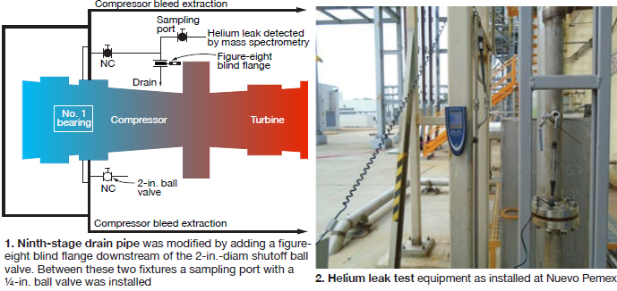
Solution. During a planned outage prior to the air leak test, plant personnel modified a ninth-stage compressor water drain pipe by adding a “figure eight” blind flange downstream of the 2-in. shut-off ball valve. Between these two fixtures, they installed a sampling port with a ¼-in. ball valve (Fig 1). During the test, we opened the sampling port, allowing continuous extraction of small amounts of air from the compressor. This enabled us to position the helium probe so that it wouldn’t affect turbine operation (Fig 2).
Next step was to determine the time it takes helium to travel from the point of spray to the sampling point. To do this, we sprayed the helium directly upstream of the first-stage filtration system. Travel time for the helium was approximately two seconds, which we used as the reference period.
Sometimes when we injected helium in areas near air prefilters—around an implosion door, for example—and the detection time was greater than two seconds, we concluded that there was a leak. However, the same air flow and turbulences suck air with helium concentration in the environment to the filtration system. When a reading suggested the existence of a leak, we found it was necessary to check the measured value against the reference value—which revealed a detection time of less than two seconds.
Using a Pfeiffer HLT560 mass spectrometry leak detector, we tested the following locations:
- Manhole registers.
- Instrumentation tubing and fittings.
- Expansion joints.
- Implosion door.
- IBH pipe flanges.
- Rainwater drain pipe between the prefilters and fine filters.
- Thermocouples.
- Nozzles for offline washing system.
Results. Staff found no major leaks, but did find small ones in the offline washing nozzles. These were sealed with silicone until permanent repairs would be possible. Note: We weren’t able to leak-test the online water wash nozzles because of high operating temperatures. However, based on our findings with the offline nozzles, we sealed the online nozzles as well during a subsequent planned outage. We found a few other small leaks in the differential-pressure transmitter fittings, one in the manhole register, and one in an expansion joint.
Plant achieved the main objective: Optimizing air flow to the compressor. Because the leaks identified and sealed were small both in size and number, technicians were not able to detect a measurable uptick in turbine performance. However, performance improvements in facilities where significant leaks are detected and repaired have been well documented.
Project participants:
Hugo Ordoñez Ruiz, plant manager
Henry Barrios García, plant engineer.
Using HRSG water to heat GT fuel gas
Challenge. Nuevo Pemex initially operated as a simple-cycle facility with an auxiliary boiler to supply hot water to a heat exchanger that preheated fuel gas for the GTs. But after conversion to a cogeneration plant, it made economic sense to use hot water from the HRSGs for preheating the fuel.
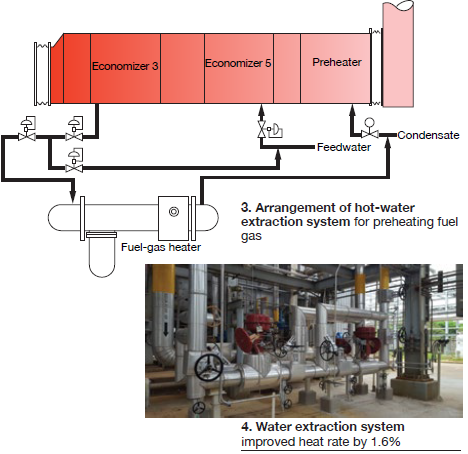
Solution. In coordination with Cerrey SA de CV, the HRSG supplier, staff designed and developed a hot-water extraction system. This consisted of a hot-water line connected to the bottom header drain in Economizer 3 to extract water at 404F. A second line to the feed pump discharge was installed to cool the water slightly before it reached the fuel heater inlet. After transferring heat to the fuel gas, water returns to the HRSG at the preheater inlet (Fig 3).
To ensure proper functioning of the gas turbine, GE stipulates requirements for flow, pressure, and temperature of the hot water supplied to the fuel heater. To assure compliance, we added a control valve to maintain water flow at 40,300 lb/hr; a second valve to attemperate the water supplied with cold water to maintain the temperature at 356F; and a third valve to release pressure if it exceeds 550 psig.
Results. The plant’s fuel-gas consumption decreased measurably after the water extraction system was installed in January 2016; heat rate improved by 1.6% (Fig 4). By cutting our fuel consumption, we also reduced greenhouse gas emissions. Running in cogeneration mode with the new extraction system, we achieved 100% reliability. (In simple-cycle mode, reliability was adversely impacted by the auxiliary boilers, which had several failure-prone components.)
The auxiliary boilers now are in reserve. The HRSG preheater condensate recirculation pumps are held in reserve as well. This is because the 250F return hot water from the new extraction system is blended with condensate (142F), bringing the temperature to 158F or more, thus preventing the flue-gas temperature from dropping below the dew point and forming condensate.
Project participants:
Hugo Ordoñez Ruiz
Henry Barrios García
Guillermo Mondragón García
Nuevo Pemex Cogeneration
Operated by NAES Corp
277-MW, gas-fired, 2 × 0 cogeneration facility located in Villahermosa, Tabasco, Mexico.
Plant manager: Hugo Ordoñez Ruiz