


 Annual meetings of the 7EA Users Group typically attract just north of 100 owner/operators of GE 7B-EA engines from half a dozen countries and about the same number of exhibitors in the vendor fair. Important, too, is that about 40% of the user attendees are first-timers, year after year. The reason, of course, is that user-group meetings are invaluable training forums.
An online forum helps users stay in touch and get answers to their questions between meetings. This service, provided by Gregory Carvalho, Simplified Technology Co, and the steering committee (box), was implemented in summer 2003. Over the ensuing 14 years there have been more than 17,300 postings and registered users can access all in the archive section at ge7ea.users-groups.com. Presentations from the last 10 meetings also are accessible via the website.
The all-volunteer organization’s scorecard identifies nearly 1200 units in the GE 7E fleet at more than 200 plants worldwide.
This report was developed from material presented at the 25th annual meeting in November 2016, virtually all of which is as current today as when the information was disseminated.
Stay connected with colleagues via the user forum at ge7ea.users-groups.com.
TILs critical to 7EA inspection success
The editors corralled Mike Hoogsteden, director of field services for Advanced Turbine Support LLC, which inspects scores of 7FAs annually, to learn how users can make their outages more productive and minimize the possibility of missing something that could contribute to a forced outage. He and his colleagues have opened every 7EA User Group meeting for the last several years with their presentation (updated annually), “What We Are Seeing in the 7EA Fleet During Our Inspections.”
A good place to start, he said, is to review the OEM’s Technical Information Letters (TILs) pertaining to the 7EA, take notes, and bring your questions to the next user-group meeting. Your colleagues and participating suppliers are the best source of advice on what’s important and what’s not, Hoogsteden added. The knowledge gained will help you plan the optimal outage for your gas turbines.
Five TILs he suggested users become intimately familiar with are these:
- 1884, “7EA R1/S1 Inspection Recommendations,” which addresses the need to inspect R1 and S1 airfoils for possible damage caused by clashing—the unwanted contact between S1 stator-vane tips and R1 rotor-blade roots during operation.
- 1980, “7EA S1 Suction Side Inspection Recommendations,” which advises users to inspect for crack indications on S1 vanes made of type-403 stainless-steel, regardless of whether clashing damage is in evidence on S1 and R1 airfoils.
- 1854, “Compressor Rotor Stages 2 and 3 Tip Loss,” which suggests blending and tipping to mitigate the impact on availability and reliability of R2 and/or R3 tip loss. This TIL supplements information provided by the OEM in the O&M manual provided with the engine.
- 1562-R1, “Heavy-Duty Gas Turbine Shim Migration and Loss,” which informs users on the need to monitor the condition of compressor shims and corrective actions available to mitigate the risks of migrating shims.
- 1744, “S17, EGV1, and EGV2 Stator-Ring Rail and CDC Hook Fit Wear Inspection,” provides guidance on the repair of dovetail wear and suggests hardware and software enhancements available to mitigate the potential risk caused by operating conditions that promote such wear.
There are many more TILs that demand your attention, to be sure. They include the following:
- 1090-2R1, “Compressor R17 Blade Movement.”
- 1067-R3, “Stage 2 Bucket Tip Shroud Deflection.”
- 1634, “Stages 2 and 3 Bucket Low-Speed Rub Prevention.”
- 1313, “Stage 3 Bucket Tip Shroud Overlap.”
TIL 1884
It took years for the OEM to address clashing in a TIL (Fig 1). Hoogsteden believes Advanced Turbine Support was the first company to alert the industry to this phenomenon—back in 2006. TIL 1884 was issued in spring 2013. During the intervening years, Advanced Turbine Support worked closely with the users to share inspection data important to problem definition and solution.
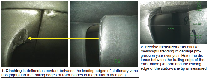
Developments in inspection technology contributed to a better understanding of first-stage findings and provided information of greater value for the resolution of issues. Follow this timeline: 2008, implementation of visible dye inspections; 2009-2010, measurements added to documentation (Fig 2); 2011-2012, inspection documentation with trending data reveals an obvious increase in damage year over year. Plus, the implementation of eddy-current (EC) testing suggests an elevated level of risk to owner/operators.
TIL 1884 went beyond clashing, recommending the checking of stator vanes for cracking in the co-called “area of interest” (Fig 3). Lock-up of vanes in carbon-steel ring segments can cause higher-than-normal operating stresses, which the OEM says “reach a maximum on the suction side of the vane near the mid-chord location.”
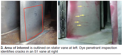
Cracking was first reported after TIL 1884 was published. In spring 2014, Advanced Turbine Support identified by way of dye penetrant two cracked S1 vanes in the same compressor. EC confirmed the findings. The company’s inspectors found cracks in more machines over the next several months. This experience revealed that some cracks can be too fine to bleed penetrant, as recommended by the OEM; however, EC was able to find them.
Hoogsteden’s suggestion to mitigate the possibility of serious damage from clashing and cracking is to perform an in-situ EC inspection to the trailing edges of all R1 rotor-blade platforms and the entire suction side of every S1 stator vane from platform to tip each peak-run season or every six months.
TIL 1980
TIL 1980, issued in January 2016, is viewed by the editors as an “addendum” to TIL 1884, addressing S1 vanes installed in legacy 7EAs (1996 and earlier) made of Type 403 stainless steel. This material is more susceptible to mid-chord cracking than the GTD™ 450 alloy used in the manufacture of vanes since 1997.
TIL1980 recommends inspection by visible means or by fluorescent dye to reveal suction-side cracks that might be present. Hoogsteden mentioned in his comments on TIL 1884 that these methods are inferior to EC for this purpose. He added that if the vanes are coated, visible or fluorescent dye penetrant inspections may not be dependable, nor have an acceptable probability of detection.
Regarding the effectiveness of ultrasonic (UT) inspection for this purpose, if coating degradation—such as disbanding—occurs, the value of UT could be compromised.
Advantages of EC Array include the following:
- It can detect crack initiation faster than UT.
- For coated vanes, the inspection equipment used by Advanced Turbine Support has the ability to maintain accuracy in flaw sizing (length and depth) for coating thicknesses of up to 0.125 in.
- Superior to in-situ liquid-penetrant inspection, which may miss small cracks.
- Two scans cover the entire suction face of a 7EA S1 vane.
Ultrasonic phased array can be used to supplement any suspect indications to confirm sizing of larger/deeper indications. But keep in mind that the UT probe does not cover the entire width of the stator vane—only about 0.75 in.
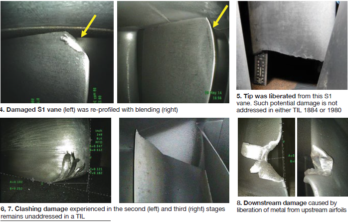
Hoogsteden went on to describe some of the damage found during its TIL 1884 and 1980 inspections, which go beyond what the OEM suggests. These are shown in Figs 4 through 8.
TIL 1854
TIL 1854, released in August 2012, informs owner/operators of E-class compressors about the blending and tipping of second- and third-stage rotor blades it recommends to mitigate the negative impact on availability and reliability caused by tip loss from heavy rubs (Fig 9) and/or corrosion pitting.
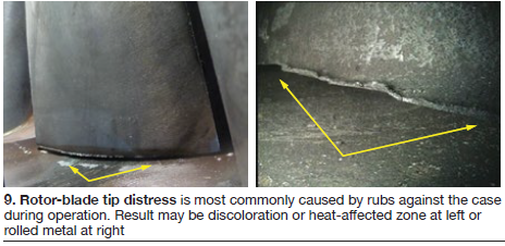
The OEM says fleet experience and engineering analysis have concluded that compressor rubs can be caused by casing distortion that progresses over time, and by hot restarts initiated between one and eight hours after shutdown. The latter causes critical clearances to decrease. Corrosion pitting, by contrast, can create a local stress concentration that may result in tip loss via high-cycle fatigue.
Hoogsteden pointed out that although this advisory does not address first-stage rotor blades, they too can suffer tip loss and should be included in your inspection regimen. For R1 and R2 rotor blades showing signs of tip distress, Advanced Turbine Support recommends, at a minimum, a visible dye-penetrant inspection to determine if radial cracks have initiated (Fig 10). For R3 blades, the company recommends a minimum of a 360-deg roll with a close-up inspection of all blade tips at the same intervals.
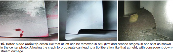
The editors asked the field-service director why his company espouses such conservatism when the OEM doesn’t. He said their recommendations are based on more than 1000 in-situ visible dye-penetrant inspections which have identified at least 64 cracked rotor blades and about half as many tip liberations.
TIL 1562
TIL 1562, issued January 2007, is likely the most familiar of the advisories in this group of five because it is more than a decade old and shim liberation has been discussed frequently in user-group meetings and in CCJ. Fig 11 provides a quick review. The left-hand drawing is of a typical shim, center photo shows a shim protruding from the compressor, right-hand picture is of a shim blended flush to the case because it couldn’t be removed completely without difficulty.
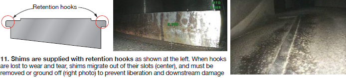
Hoogsteden recommends that users develop a shim map for their compressors to identify locations where shims might have been installed, then audit those locations for shims remaining. The map should be updated after every inspection. Shims protruding from the case by less than one-quarter of an inch should be monitored regularly. When the shim protrudes into the flow stream one-quarter of an inch or more it should be removed or ground off.
TIL 1744
TIL 1744, issued September 2010, said 7EAs operating at part load when ambient temperature is less than 40F are at risk for major damage caused by the lifting of 17th-stage vane segments. As the segments lift up they damage the hook fits and turn into the rotating blades.
A non-OEM repair procedure described at a user group meeting attended by the editors involved milling of the damaged slot to accommodate 18-in. inserts. They were installed in the upper and lower halves of the case to retain the new vane segments. The inserts are held in place with setscrews. The user describing the procedure cautioned against considering it a permanent fix because a root cause analysis had not been completed.
Mike Hoogsteden can be reached at mhoogsteden@advancedturbinesupport.com.
User presentations
Presentations by owner/operators are highly regarded at user-group meetings. The first-hand experience detailing how a particular job was conducted, what worked/what didn’t, lessons learned, etc, can be invaluable to someone considering a similar project. Plus, there’s the opportunity to ask questions and get straight-forward answers.
Seven user presentations from the 2016 7EA Users Group conference, profiled below, are accessible to registered users on the organization’s website. The titles reflect the diversity of material shared at a typical 7EA meeting—including HV electrical, generators, gas turbines, valves, etc.
- Bus replacement.
- TIL 1398 inspection of stator-end winding axial support system hardware.
- Hot-gas-path component life.
- 7EA maintenance strategies.
- Gas valve upgrade.
- 7EA compressor issues.
- Wrapper leak mitigation.
The bus-replacement presentation describes in photographic detail the retrofit of 15-kV/4000-amp circular non-segregated (non-seg) bus. More than seven-dozen images of the components and their assembly and installation, foundations, plus detail drawings, walk you through the project quickly. A companion presentation, made by Bruce Hack of Crown Electric Engineering & Manufacturing LLC, covering circular non-seg bus, switchgear and circuit breakers, also is posted on the 7EA Users’ website. (Backgrounder: “High-voltage electrical emerges as a top interest area among GT users,”)
TIL 1398-2, issued in March 2003, is applicable to all hydrogen-cooled, medium-size generators manufactured between July 1988 and September 2002. Its purpose is to remind users to inspect the tightness of the stator end-winding support hardware for loose, missing, and non-locking fasteners. Photos show damage done by liberated fasteners and how fasteners can be fixed in place with epoxy to mitigate the issue.
A table included in TIL 1398-2 identifies machines susceptible to loose fasteners (such as the GE 324 steam turbine/generator, 9A4, and 7A6), gives part numbers of interest, etc.
HGP component life reflects the experience of three 7EAs, each having a nominal 20 years of cogeneration service. The baseload units had operated roughly 165,000 fired hours and had fewer than 200 starts, respectively. Inspection schedule was combustion every other year, HGP every four years, and major every eight years.
Buckets:
- First stage. DS GTD-111, 12 cooling holes, GT 33 coating and TBC. Typically repair at HGP and replace at about 100,000 fired hours. Longest demonstrated run was 105,000 fired hours.
- Second stage. IN-738 and GTD-741, 10 cooling holes, scallop shroud, cutter teeth. Typically repair at HGP or major and replace at 100,000 fired hours. Longest demonstrated run on IN-738 buckets with eight cooling holes was 100,000 fired hours.
- Third stage. U-500, cutter teeth. Typically repair at HGP or major and replace at about 135,000 fired hours. Longest demonstrated run was about 140,000 fired hours.
Nozzles:
- First stage. FSX-414 with full MCrAlY and TBC coating. Repair at HGP and replace when no longer cost-effective to repair. Longest demonstrated run expected at next outage would be 140,000 fired hours. At the time of the presentation a set of nozzles with about 130,000 fired hours was at a shop for repair.
- Second stage. GTD-222 with MCrAlY coating. Repair at HGP; replace when no longer cost-effective to repair. Longest demonstrated run expected at next outage would be about 162,000 fired hours.
- Third stage. GTD-222. Repair at major; may replace at 200,000 fired hours or when no longer cost-effective to repair. Original sets of nozzles still in machines with about 165,000 fired hours of service and two repair cycles.
Shroud blocks:
- First stage. HR-120 with cloth seals.
- Second and third stages. Honeycomb.
7EA maintenance strategies. This presentation, rated “must review” by the editors, offers valuable insights based on the extensive experience of both the user and his company. The power producer has 51 7EA peaking units (no baseload) installed at six stations; 39% of the engines have Type 403cb stainless steel S1 airfoils, the remainder GTD 450. The strategies discussed had to do with S1 failure mitigation, post-outage performance loss, and rotor end-of-life.
Regarding S1, the speaker first reviewed inspection options, then discussed the company’s original failure-mitigation program and why some tweaking was required. He then explained the updated plan and reviewed ongoing development of yet another mitigation plan (referred to as the “alternative” plan) based on the efforts of EPRI and its members.
TIL 1884. The speaker addressed TIL 1884 first, noting that the OEM recommends dye penetrant for NDE. The user’s engineering department does not agree, believing greater accessibility is needed for a proper dye-penetrant inspection, excessive application of dye-penetrant chemicals is required, and results are inconsistent. It recommended eddy current (EC), finding it is easier to implement, results have less variability, and helps identify crack indications at a higher success rate. If an indication is found, the engineering department recommends confirmation with FPI (fluorescent penetrant inspection).
For more on TIL 1884 and what others think about the use of dye penetrant to achieve its goals, see the section above focusing on 7EA compressor inspection.
Continuing, the speaker said his company embraces 100% borescope inspection of the R1/S1 area for clashing and of recording clashing damage, if found, with photos and measurements. Mapping of clashed stators also is done.
Here’s how the speaker summarized the company’s S1 failure mitigation observations and efforts:
- Corrosion of carbon-steel ring segments reduces vane damping and increases stator stresses if a rotating stall is experienced during startup and/or shutdown.
- At the time of the presentation, S1 failures associated with GTD 450 were airfoil tip liberations; with Type 403cb stainless steel, root liberations. The latter failures can occur with no clashing.
- TIL 1884 recommends dye-penetrant inspections only for units experiencing clashing. It does not address units with 403cb airfoils which may have crack indications without signs of clashing nor does it offer a method for determining the magnitude of indications.
- The speaker’s company has qualified EC as its preferred method of S1 inspection.
- The power producer also evaluated its 7EA fleet based on S1 inspection results compared to operational profile and parameters, finding no correlation to predict S1 crack initiation and when an S1 failure would occur.
Post-outage performance loss. A relatively common complaint of owner/operators presenting on their recent major inspection experience is the deterioration of performance following restart. The editors have heard this at several user-group meetings with no particular OEM or third-party vendor singled out.
The 7EA speaker discussed performance loss after a combustion inspection (rare) and HGP. The typical finding: Pre-outage NOx margin was different that post-outage. Engines were tuned to lower firing temperatures to assure environmental compliance. The result was a 3- to 5-MW decrease in output. The user’s company, the OEM, and various third parties believe fuel/air variation explains the performance issues.
The owner has been flow-testing liners and comparing results against post-outage performance to determine allowable flow tolerances—this to maintain firing temperature at the highest possible level and prevent loss of top-end megawatts. Another objective is improved repair processes to achieve repeatable results with vendors and reclaim lost output.
Rotor end of life (EOL). The speaker explained the following four options for rotor failure mitigation:
- 1. Replace the existing rotor with a new or refurbished one. This is the highest-cost/lowest-risk option but one seriously worth considering if you have majors for multiple units in the same year.
- 2. Refurbish to regain half a lifecycle. This is a less expensive but higher-risk alternative than the first option.
- 3. Replace key rotor components to achieve life extension—less expensive than the first two options with less risk than the second.
- 4. Inspect but do not repair may be the option of choice depending on the strategy for unit retirement. This is the lowest-cost/highest-risk option of the four presented.
The presenter closed by listing critical items to consider before formulating an EOL evaluation plan and selecting a vendor:
- Availability of rotor discs (OEM or third-party manufactured) if one or more do not pass inspection.
- Capability of the EOL contractor for replacing one or more discs—if necessary.
- Candidate contractor’s rotor inspection capabilities and experience.
- Candidate contractor’s EOL analytical and engineering capabilities.
The gas-valve upgrade presentation provides some project photos, data, calibration settings, operating parameters and other information of value to users considering migration from hydraulic actuation to electric. This information, combined with the experience from a recent Frame 5 fuel-valve upgrade, should help any owner/operator considering a similar project.
7EA compressor issues. A hands-on engineering manager discussed issues experienced during execution of TIL 1884 recommendations. If clashing is in evidence, removal of S1 vanes may be necessary. Options for removing them: Pull the rotor or leave the rotor in place and try to push the lower-half ring segments out of the case. The presentation illustrates how the OEM’s stator removal tool handles the task with the rotor in place.
The speaker said the special tooling was successful on both machines serviced, but the task was challenging. On one unit, the hydraulic power unit developed 3100 psig to free up segments with heat and quench. The other unit required 5200 psi to break loose the ring segments.
Other discussion points: Replacement of a failed R17 blade (TIL 1346), shim pinning according to TIL 1562-R1, and turbine shell-to-exhaust frame slippage (TIL 1819-R2).
Registered users can access the presentations summarized above on the organization’s website at ge7ea.users-groups.com.
Wrapper leak mitigation
It’s the rare 7EA Users Group meeting that does not have some discussion on attempts to mitigate leakage from combustion-wrapper joints. “Attempts” is italicized because success has been elusive. Jason Hampton, who chaired the steering committee until exiting the user side of the industry early in 2017, presented on the documented, deeply rooted frustrations experienced by owner/operators since before the millennium, to eliminate leakage at casing joints—the four-way joints in particular.
Hampton generally attributed leakage to an OEM design issue, which, in his opinion is related to insufficient clamping force in suspect areas. A contributing factor is casing distortion suffered during operating regimes not envisioned by designers.
He invested a considerable amount of personal time to peruse the 7EA User Group’s discussion-forum archives hosted on its website at ge7ea.users-groups.com and to survey owner/operators about their experiences. Here are a few of the comments, shared in several discussion threads on the forum from 2004 through 2012; most have been edited to reduce word count:
- Split-line gaps on 7EAs are common and to my knowledge GE does not offer an effective means for eliminating wrapper leakage. Sealants have been tried with limited success.
- We are experiencing split-line leaks on all six of our Frame 7s (five purchased in 1989, one in 2001).
- We ensured that the OEM torque sequence/procedure is being done correctly. Result: Leaks slowed at first. Grooved the upper casing on one unit and installed a keyway in the groove; this helped for about eight months. Tried several different sealers, but they were effective only for a short period.
- On our recent major inspection, we followed jacking instructions to the letter. Plus GE executed the work and the field TA (technical advisor) was one of the best in the business. We still have leaks.
- Leaks on the turbine/wrapper horizontal joint were mitigated by welding straps on the outer casing. Further investigation revealed internal leaks by the combustion cans.
- The original key-way mod was performed on one unit in 2006 but we still have a leak on one side at the horizontal joint. The bottom line: Money was not well spent.
- We tried peening, re-torqueing, welding, and the seal-key mod with little success. The unit where the original seal key mod was installed leaked worse after the repair than before.
- Peening over mating areas reduced the amount of air leaking by the joint but did not eliminate leakage.
 Hampton then reviewed the various leak-mitigation methods attempted by the OEM, contractors, and users with marginal success. Here are the editors’ notes from that portion of the presentation:
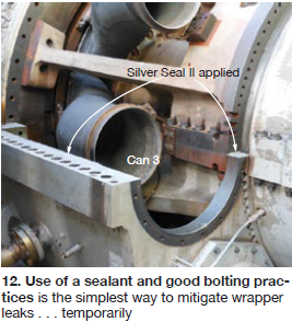
Sealants, standard bolting practice. Research suggested that a sealant and proper bolting should provide temporary leakage relief (Fig 12). However, expect fluid temperature and pressure to erode or blow out the sealant over time. Obtain appropriate torque values from GE spec 248A4158, “Bolt & Stud Torqueing.”
Among the sealing products suggested: Silver Seal II, a non-hardening fibrous paste that flows into rough or irregular surfaces and expands under heat, curing to a leathery-like consistency. Manufacturer IGS Industries, Meadow Lands, Pa, claims it will not crack from thermal cycling or vibration. Two additional high-pressure/high-temperature sealing compounds suggested by users include Esco Products Inc’s (Houston) Copaltite and ICS Industries’ Turbo-R and Turbo-50.
Weld wrapper horizontal joints together. This is a relatively straightforward process with split-line cans 3 and 8 removed (Fig 13).
Weld strips of plate steel on the outside of horizontal joints. This, too, is relatively straightforward as Fig 14 shows.
Peen horizontal joints after proper tensioning and removing combustion hardware.
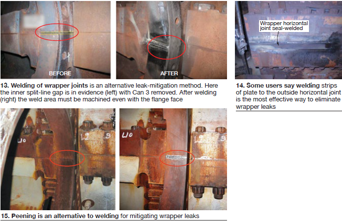
The goal of peening is to spread metal over the joint area where leakage is occurring (Fig 15). Ways suggested for doing this:
- 1. Use an air hammer with a punch attachment.
- 2. Strike the casing along the length of the joint, both above and below the joint, using the ball end of a ball peen hammer.
- 3. Hammer and chisel along the length of the casing both above and below the joint.
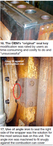
Perform “original” seal key mod. This “solution” calls for machining slots in the outer wrapper (Fig 16). Lower-half horizontal joints are machined; the upper half is flipped and supported for the machining activities. Next, install seal keys into the lower-half horizontal joints. The time-consuming and costly mod was said to offer only marginal benefit. Industry consensus is that this is not an effective method for sealing the wrapper.
Install custom shims in horizontal joints. Procedure is as follows:
- Hone horizontal joints.
- Install the upper-half wrapper and torque.
- Measure gaps along the horizontal joints.
- Remove the upper-half wrapper.
- Install shims in gap areas.
- Reinstall/torque the upper-half wrapper.
 Retrofit unit with HYTORC tensioning hardware. The three-piece fastener from UNEX Corp’s HYTORC Div is a direct replacement for any type of helical nut. The main reason for its introduction to the 7EA fleet was to reduce the time for bolting/unbolting during outages. The precise bolt tensioning offered by this alternative also was believed to offer more precise torqueing and better flange tightness. However, clashing experienced between the tooling and casing in some areas did not allow for HYTORC nut installation.
Install angle iron at wrapper outer joints. This method was implemented on the right side of the unit described in Fig 17 because it was the only area of significant leakage after installation of the original seal key mod. Think of this as a unique solution to a unique problem.
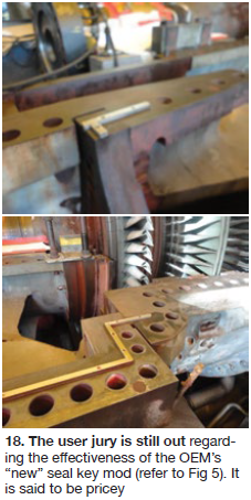
Perform “new” seal key mod to the compressor discharge case and wrapper.
This relatively complex mod is performed only by GE (Fig 18). It is said to be expensive—perhaps into the mid six figures. No users with first-hand experience were found by Hampton in his research.
Jason Hampton can be reached at jason.hampton@yahoo.com.