Keep up with OEM advisories
(All diagrams and photos are posted at the bottom of this article.)
 Plant managers are always pressed for time and keeping up with OEM advisories can be challenging. But it’s important to do so. You don’t want to overlook an issue that could cause a forced outage which should not have occurred.
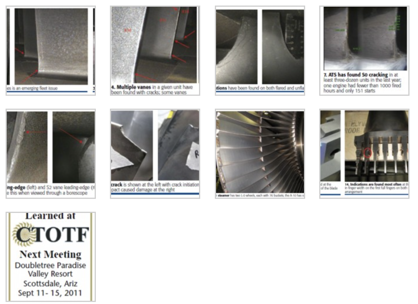
The GE Roundtable focusing on F-class engines at CTOTF’s Spring Turbine Forum (April 10-14, Palm Beach Gardens, Fla) was dominated by open discussion of topics on the minds of owner/operators. One talking point introduced was trailing-edge cracks on the lower half of SO vanes. The user said several plants have identified such cracking recently (Figs 1, 2).
Consensus view: SO cracking is an emerging fleet issue and every plant should schedule a borescope inspection when convenient. Eddy current inspection was said to have been successful in identifying SO cracks; also that indications won’t necessarily bleed red dye during a penetrant inspection.
As the microphone was passed around, the CTOTF members offered the following additional information:
- The presence of a 2-in. crack had been confirmed (Fig 3).
- Multiple vanes in a single compressor had been found with a single crack each.
- Multiple cracks were identified on multiple vanes in a single unit (Fig 4).
- Indications known to this group were in flared compressors.
No one present for the roundtable could recall a Technical Information Letter on the subject, nor had anyone heard of a critical crack length that when reached should prompt an immediate shutdown. Another unknown: crack propagation rate.
The editors contacted Rod Shidler of Advanced Turbine Support Inc (ATS), Gainesville, Fla, which performs hundreds of F-class engine inspections annually, to see if he had seen S0 cracking. “Of course,” was the immediate reply and he provided the photos shown here of units his team has inspected. He also said that TIL 1509-R1 (Mar 8, 2011) covers the requirements for this inspection.
In early May, Shidler called to say that an inspection, still in progress, of an unflared 7FA compressor revealed trailing-edge cracks on two SO airfoils and tip liberations on two others (Figs 5, 6). This was the second unflared unit inspected in the last two weeks by ATS that had SO vane damage.
Shidler told the editors that SO distress had been associated with flared units but these findings show that the unflared units are not immune to S0 vane issues as most in the industry had believed.
Also significant was that the trailing-edge cracks in both S0 vanes were found above the midspan of the airfoils. These findings are not consistent with TIL 1509-R1, which states that crack locations vary from “the root of the vane to approximately 50% span.”
The Technical Information Letter also states, “SO NDI is only recommended for flared units” in the Table 1 inspection recommendation footnotes. Plus paragraph 4B says, “An SO inspection is not required for unflared compressors.”Shidler went on to say that ATS has found SO cracking in at least three-dozen units during the last year, including one engine at the end of April with fewer than 1000 fired hours and only 151 starts (Fig 7). He believes that perhaps no 7FA can be considered immune to S0 cracking. During a recent visit to a four-unit plant, he found three units with cracked SO vanes.
In addition to SO cracking, Shidler said R2/S2 and R3/S3 clashing, and R1 tip cracking, are compressor issues that most concern 7F users today. Loss of turbine-wheel balance weights and cracks in the fingers of titanium 40-in. L-0 blades in D-11 and A-10 steam turbines are two more areas of critical importance.
Clashing incidents continue because the root cause remains unknown (Figs 8, 9). Several users, and Shidler as well, have reported on the clashing of rotating blades and stationary vanes at recent meetings of the CTOTF and 7EA and 7F Users Groups. The ATS president said clashing typically is identified with Rows 2 and 3 in the 7FA. It occurs in the bottom half of the compressor casing between the 5 and 7 o’clock positions and in the upper half of the casing between the 10 and 2 o’clock positions.
R1 tip cracking is an acknowledged fleet-wide problem (Figs 10, 11). Users are referred to TIL 1509-R1 for the latest information available from the OEM on the R1 tip-cracking issue. Cracking is caused by rubs that can result from over speed, fast starts, open doors, foundation distress, and wet operation.
Turbine section. Inspection helps avoid balance-weight roulette in the turbine section, Shidler continued, noting that cracking had been found in the first-stage balance-weight grooves on several 7FAs. Possible “locking mechanisms” for the balance weights may be peening, staking, or welding, depending on work done on the forward face of the disk post commissioning. Borescope inspection, while difficult to perform in this area, according to Shidler, can identify cracking conducive to balance-weight liberation. Consult TIL 1742, he advised.
Steamer alert. In early spring, the editors were told about the failure overseas, last fall, of a 40-in. titanium L-0 bucket (Fig 12). That report has not yet been verified independently. However, a call to Shidler confirmed that cracking was indeed evident on the blade-root fingers of L-O stages that ATS personnel were shown by some customers.
Bullets below are some of the unconfirmed “facts” made available to the editors by parties other than the OEM:
- The two-flow LP section of the D-11 has two L-O wheels, each with 76 buckets; the single-flow A-10 has one L-O wheel.
- Initially, steam-turbine users having 40-in. titanium buckets in their machines and more than 2000 starts were informed by the OEM that their L-O stages required inspection. Later the “must inspect” threshold was reduced to 1500 starts. At least seven units had been inspected before May.
- The initiation and severity of cracking appears driven by start/stop cycles. Two units inspected early this year had between 1500 and 1700 starts and all buckets inspected had cracks at the step-down locations (Fig 13). The cracks ranged in length up to 0.5 in.; crack depth was more than 0.2 in. in some cases.
- The OEM’s inspection, at least for the first few units, required a four-week outage to remove the rotor and buckets and perform an FPI inspection.
- Indications are found most often at the first step-down in finger width on the first full fingers on both sides of the root arrangement (see highlights on Fig 14). At least one owner/operator reported indications on every bucket in the disk.
- For buckets having no indications, the holes for the retaining pins are reamed and oversize pins are used to reattach the airfoils to the wheel.
- In cases where many buckets are affected and spares not readily available, a possible alternative to replacement is to machine off the L-O buckets at the wheel OD and put the rotor back in service. Output is reduced, of course—perhaps by 25 MW per wheel modified in this manner.
- A redesigned L-O bucket is expected shortly.New inspection service from ATS. Shidler said that customers have asked ATS to evaluate the issue and to develop an inspection method that would not require rotor and bucket removal to identify cracking.
Dustin Irlbeck, the lead on this project, said the company has developed an in-situ technique that will require approximately two days for a D-11 and one day for an A-10 steam turbine. It is capable of finding indications that FPI will not. CCJ
(Click to see as a slide show.)


