


New exhaust seal assures effective fire protection
Best Practices Award
Challenge. The OEM-supplied enclosure exhaust seal was never air tight and degraded over time to render the fire protection system potentially ineffective.
Solution. Site engineering personnel and EagleBurgmann KE Inc collaborated on a low-cost design that allowed the exhaust section to expand freely and maintain the air-tight seal, thereby enabling the fire protection system to work effectively if required.
Calpine Corp’s Fire Protection Standard required the site to conduct a “daylight inspection” of the fire protection seals on the GT enclosure after each outage. The deterioration of the foam seal and inability of the manufacturer to supply replacement foam drove the site to investigate other options.
Construction of the seal is two parts:
- The seal material is a lightweight, high-temperature fabric also used on the vendor’s exhaust-to-HRSG transition seal. Success of the EagleBurgmann product in this application allowed for its adaptation to this site’s conceived design.
- The construction material consists of galvanized metal bracketing. Angle iron, which was curved, is screwed to the enclosure side wall and secures the fabric. Flat bar bracketing holds the fabric to the exhaust cylinder. The design allows for a secure fit to each component while allowing relative motion so the exhaust cylinder can expand.
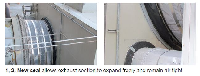
 Results. The seal performs better than the OEM design (Figs 1, 2). If there were a fire protection event, this seal would easily provide the barrier to air allowing the fire suppressant systems to operate properly.
The seal is being marketed and sold to other sites as a replacement for the OEM exhaust- cylinder-to-enclosure seal. This site has replaced three seals and a sister site is in the process of converting its seals as well.
Project participants:
Kent Locker, operations manager
Joe Bogle, plant engineer
Michael Viau, EagleBurgmann KE Inc
Local level indicators improve safety, inventory management
Challenge: Improve the visibility of tank levels at remote locations. Motivation was to improve safety during unloading operations. Field operators and truck drivers would be able to monitor tank level without contacting control room operators (CROs) who at times are busy with other critical tasks.
Solution. Chemical storage tanks of varying sizes and containing different products are located in several remote areas of the site. These tanks were installed originally with electronic level transmitters; signals were transmitted to the control room. However, some of the small tanks were equipped with level transmitters located about 20 in. from the bottom of the tank.
In either case, during rounds and during filling operations, field operators had to contact the CRO to monitor the level, or in the case of level indicators mounted 20 in. from the bottom of tanks, the field operator would have to enter the diked area to see the level on local level gages when inventory was low.
To improve the situation, and especially eliminate operators from having to enter the diked areas, it was decided to install pulsed radar level transmitters in the location of the high-level switches. The radar transmitters can be purchased with the same connection as the level switches and in some cases the same wiring could be used. Now each tank has a level that can be monitored in the control room, measure the entire level, and each was configured for high- and low-level alarms.
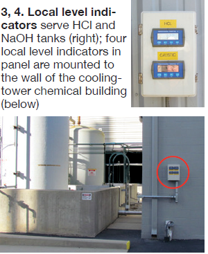 Further improvements came when it was suggested to add local level indications to two tanks located at the north end of the demin building. These are the HCl and the NaOH tanks (Fig 3). During filling operations the field operator would have to contact the CRO to determine the starting level point, to verify that the level was increasing, and determine the end point. Remote level indicators were mounted in an enclosure and the enclosure mounted on the wall convenient for the field operator and the truck driver to monitor during filling operations.
This was so well received that the operators requested that a similar system be added to the cooling-tower chemical tank farm. Again, we installed four local level indicators in a panel and mounted it to the wall of the cooling-tower chemical building (Fig 4). The location is highly visible to the operators making rounds and is used to verify tank levels prior to filling and at the end of the filling. It also indicates to the field operator and the driver that the level in the correct tank is indeed increasing.
Results. Operators no longer need to enter the diked areas, levels are highly visible, and the drivers see what is actually occurring. The CRO is not constantly being interrupted if other activities are taking place. Overall it was a good project that improved the operations and safety as well as looks good during inspections and audits. Most importantly it demonstrates that team work and employee involvement are critical to the success at this plant.
At a cost of less than $10,000, this was money well spent.
Project participants:
Joe Bogle, plant engineer
Kent Locker, operations manager
Ken Carter, ICE tech
Decatur operations team
Decatur Energy Center
Calpine Corp
800-MW, gas-fired, 3 × 1 combined-cycle cogeneration facility located in Decatur, Ala
Plant manager: Mike Gough