


Maintaining fire protection during an outage
Challenge. Effingham County Power’s fire protection system consists of one 2000-gpm motor-driven pump, one 2000-gpm diesel-driven pump, one 25-gpm electric jockey pump, and associated equipment and controls. The jockey pump maintains system pressure above the start setpoints for both fire pumps during no-flow conditions. Pressure switches automatically start the pumps when system pressure drops below the setpoints.
Power for the electric pumps and their associated equipment and controls is supplied from a common 480-Vac breaker housed in a switchgear with station service its only source of electricity. When the station-service transformer is taken out of service for maintenance, the two electric pumps are de-energized. Because the jockey pump is de-energized, it is unable to maintain system pressure above the starting setpoints of the fire pumps.
With the electric pump de-energized, the diesel unit will start once system pressure drops below its associated pressure-switch setpoint. When the diesel pump starts, it activates the plant-wide fire alarm; all staff and contractors must stop work and evacuate the plant when the alarm sounds.
Plant management needed a way to keep the fire main pressurized when the plant was on backup power and the electric fire pumps were de-energized.
Solution. Plant personnel ran the diesel pump intermittently to maintain system pressure, to prevent erroneous fire alarms and work stoppage. This resulted in unbudgeted diesel fuel costs and excessive emissions, which could possibly lead to Effingham exceeding air-permit limits.
Plant personnel identified the nearest motor control center supplied by a backup source of power when station service was de-energized. The closest spare breaker was about 150 ft away and required extensive trenching to run supply cables to. But a welding receptacle, which has a secondary source of power, was located only 50 ft from the fire-pump building. Staff determined that the rating of the welding supply power was sufficient to operate the jockey pump.
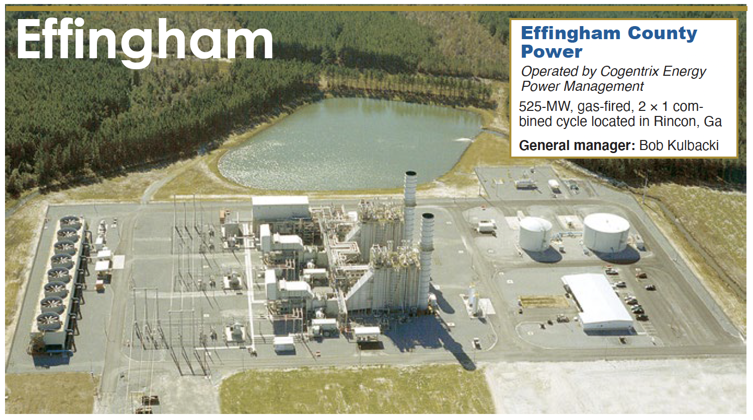
The plant purchased a double-throw safety switch, one plug, and the necessary cable to connect the welding receptacle (Fig 1) to the switch located at the fire-pump building (Fig 2). Total cost of the materials to complete the project was $500. The two plugs were connected to the supply cable to make a jumper cable (Fig 3) to connect the welding receptacle to the fire-pump building.
During an outage, with station-service power de-energized, the switch was permanently wired to the jockey pump’s primary power supply and one end of the temporary supply cable. Next, the temporary supply cable was connected to the welding receptacle. Then the welding receptacle was energized and staff swapped the jockey pump from normal to temporary power.
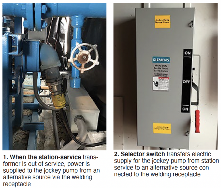
Results. The jumper cable is stored in the fire-pump building to ensure its availability at all times (Fig 4). Prior to securing station-service power, the jumper cable is connected to the designated welding receptacle. When station-service power is de-energized a technician energizes the welding receptacle and swaps the safety switch from normal to temporary power, thereby providing power to the jockey pump. Fire-protection integrity is maintained in this configuration because the diesel pump will start if system pressure drops below the setpoint.
With the jockey pump in service, spurious alarms and work stoppage have been eliminated. This project has been a cost savings because outage interruptions have been reduced and the need to operate the diesel pump intermittently to maintain system pressure is no longer required.
Project participant:
Russell Howell
Assuring voltage-schedule compliance
Challenge. The transmission operator has provided Effingham County Power four voltage schedules which change throughout the day: 0000-0600, 0601-1800, 1801-2100, and 2101-2400. Control room operators (CRO) are required to maintain the schedules within a ±2 kV band. In the past, the CRO ensured the plant was in compliance with the schedule by visually confirming the plant’s “white line voltage” and adjusting the generator’s output voltages accordingly.
To avoid operating outside the control band, a generic alarm was developed to alert operators. A narrower band was established but did not vary with the changes in the voltage schedule.
To prove to the regulatory agency that the plant was in compliance, staff developed a monthly comparison spreadsheet showing plant voltage and the allowable voltage band for each minute. This required manually inputting over 44,000 data points into the spreadsheet and reviewing to verify the information was correct.
The plant’s output voltage values were populated into the spreadsheet from the DCS historian. Obtaining the necessary data for the control bands required review the shift turnovers for the past month and manually inputting these values. Once all data were entered, the spreadsheet was reviewed for compliance and saved for future audits.
Solution. The voltage schedule is determined by Georgia System Operations Corp under NERC standard VAR-002 and issued to the plant daily. If a change is made to the voltage schedule, the alarm will not change based on the current logic. This increased the potential for human error in keeping the plant operational within the established schedules.
To alleviate this issue, staff created a series of logics and graphics in our DCS (Emerson Ovation) that would allow the operators to select which schedule is currently in effect. This input is then compared to the time of day to generate the correct alarm band for the plant. The programmed alarm will alert the CRO if the plant’s white line voltage deviates from the designated voltage schedule.
If the operator continues to operate outside of the required voltage schedule, a second alarm is
generated notifying the CRO that the plant is still operating outside of the voltage range and that it is approaching compliance limitations.
The voltage schedule, control band, and time are new logic points designated in the DCS system. All values are fed into the DCS historian for retrieval as needed to show evidence of compliance to regulatory agencies. The need for manual data input has been eliminated, reducing human-error issues and saving time during monthly reviews of VAR-002 data.
Results. New graphics and logic have allowed both operators and management to ensure the correct voltage schedule is maintained. Additionally, the alarm points and trending capabilities have enabled Effingham personnel to accurately determine if the voltage schedule is consistently maintained for reporting requirements.
The monthly spreadsheet can be updated quickly, and the plan can show compliance in the time it takes to retrieve the data from the historian.
Project participants:
Bob Kulbacki, general manager
Michael Sears
Jobie Seward
Relocation of grease fittings simplifies PM
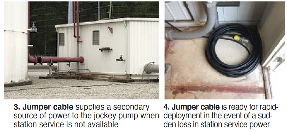
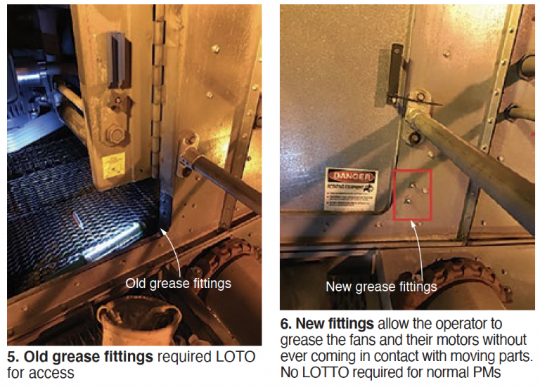
Challenge. The original design of the inlet-chiller cooling-tower fan specified the location of grease fittings inside the fan enclosure, limiting accessibility to the fan bearings for maintenance (Fig 5). To perform bearing PM, technicians had to place a LOTO on each fan and post a confined-space permit before entering the enclosure to grease the bearings. The prerequisite steps to establish a safe work environment took approximately two hours for each fan, while greasing the bearings took only 10 minutes.
Greasing of fans typically occurred when the chiller was shut down, causing no loss of generation. But there were several instances when a fan required greasing when the chiller was online. In these cases plant output was reduced by about 2 to 3 MW.
Technicians were tasked with finding a more efficient and safe method for performing this PM.
Solution. The best option discussed was to locate the grease lines on the outside of the fan enclosure (Fig 6). This would eliminate the need to secure the fan and issue a confined-space permit. Staff purchased the ¼-in. stainless-steel tubing and fittings required for about $500.
The remote fittings are attached to the bearings using the ¼-in. lines; flexible hose supplies grease to the fan housing platforms (Fig 7). A hole was made in the metal housing, and a zirc fitting mounted on the housing, to allow remote greasing.
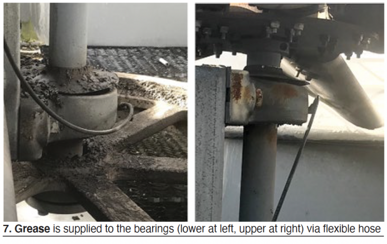
Results. Technicians now can grease the chiller cooling-tower fan bearings when the fans are operating. This will help prevent bearing damage, and when an abnormal noise is detected, a technician can quickly apply grease to ensure proper lubrication.
The amount of time saved when performing the greasing PM allows the technician to perform additional work within the plant. Overall, the results are a more timely completion of the PM and improved fan reliability.
Project participants:
Howard Beebe
Mark Gunter
Split bearing facilitates bearing replacement
Challenge. One of the chiller cooling-tower fan bearings failed, resulting in the loss of tower cooling efficiency and of plant output. Because the fans are located 42 ft above grade, and the fan assembly is about 8 ft across, replacing the bearings without use of a crane would not be safe, or technically possible. With a crane it would take two days to remove the fan, replace the bearings, and reinstall the fan—with an out-of-pocket cost of about $3200.
The maintenance team was charged with finding an easier and less expensive way to replace the bearings.
Solution. The team researched alternative solutions for replacing the OEM’s single-piece bearings and opted for using slightly more expensive split bearings of the same rating, which would not require fan removal. Another benefit of the split design: Less time to replace a bearing by a factor of four—4 hours versus 16 for the original.
The initial installation of a split bearing was time-consuming, and the limited work area made it difficult. One reason: The mounting holes for the split bearings were not a direct match to those for the OEM’s bearings, so the mounting base required modification. Additional attention also was required to maintain correct shaft alignment to ensure proper fan operation.
Crews were rotated during the installation to keep everyone fresh and working safely. The new bearings were installed without incident and the plant has had no issues since the fan returned to service. Over time, as OEM bearings fail from wear and tear, they will be replaced with split bearings.
Results. By transitioning to split bearings the plant was able to return the equipment to service sooner than anticipated, increasing plant output. Plus, the new bearings eliminated the need for a crane, saving $3200.
Project participants:
Sean O’Neill
Paul McKuhen
Russell Howell
Squeezing a new air compressor into existing space without a forklift
Challenge. A compressor failure left Effingham County Power with only one source of compressed air. If the remaining compressor were to fail, plant production would be lost. A rental compressor was brought in to mitigate risk. However, the rental did not have auto-start capability, so it was unclear if this unit could be brought online fast enough to prevent a loss of control air, without which the plant would be forced to shut down.
A new compressor was ordered and quotes were received to remove the old unit and install the new one. Quoted cost for removal and installation was more than $11,000.
The maintenance crew was challenged to find a more cost-effective and safe method to replace the plant air compressor.
Solution. Team members responded with a more efficient and inexpensive solution. The air-compressor room configuration made it unfeasible to remove a wall, or the roof, to make the switch. The size and weight of the compressor was a consideration when planning the replacement (Fig 8).
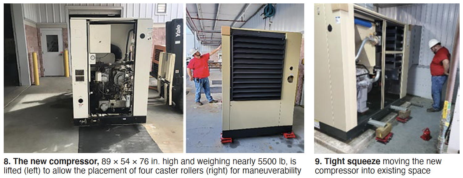
The limited space in the compressor room did not allow for the use of a forklift or other powered equipment. With building modifications unacceptable, team members decided to roll out the old compressor and roll in the new one using caster rollers and jacks. Four caster rollers rated for 17,600 lb each, and two jacks rated 40,000 lb each, were purchased ($600) for the task.
The old compressor was lifted using the bottle jacks and placed on channel iron supported by the four swivel caster rollers. This allowed maneuvering the compressor in the restricted space. The old unit then was rolled out of the compressor room and the process reversed to install the new compressor. With the new unit in place (Fig 9), plant personnel completed the installation of the required ductwork plus all control and power terminations. The compressor OEM commissioned the unit.
Results. The exchange of air compressors was completed safely in about 32 man-hours at a cost of $1100. But the cost saving of performing this task in-house was only one benefit. Another was the experience gained by plant personnel, as well as the increased level of reliability that the new compressor added to Effingham. The tools purchased for this project will be reused in changing out the second air compressor as well as other limited-access projects in the future.
Project participants:
Sean O’Neill
Paul McKuhen
Russell Howell