


When Araucaria Power Station successfully completed acceptance tests in September 2002, no one thought the facility would spend the next four years in layup and, in the process, become a center of excellence for equipment preservation that would earn plant personnel the respect of combined-cycle owner/operators worldwide.
The 484-MW, 2 × 1, 501FD2-powered facility was built in southern Brazil, near Curitiba, the capital of Parana state, by a consortium consisting of El Paso Corp, Copel, and Petrobras. El Paso is the gas producer known to most readers, Copel is the state-owned electric and telecommunications firm known officially as Companhia Paranaense de Energia, and Petrobras is the semi-privatized oil giant controlled by the Brazilian government and known formally as Petroleo Brasileiro SA. El Paso later sold its 60% share in the facility to Copel, which now owns 80% and operates the plant; Petrobras holds the remaining shares and manages the gas supply and electric sales.
The hold-up in commercial operation had to do with contractual terms in the power purchase agreement that were not consistent with the intent of Brazilian laws.
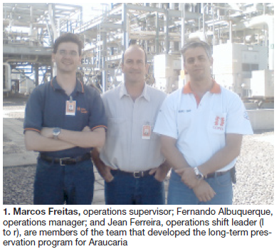
Over the four-year layup, Araucaria’s O&M team developed and implemented a comprehensive equipment preservation program for the outdoor plant. Operations Shift Leader Jean Carlos Nunes Ferreira, Operations Supervisor Marcos de Freitas, and Operations Manager Fernando Cavalcanti de Albuquerque (Fig 1) told the editors that OEM recommendations were strictly followed during this process.
Proof of the program’s success was that recommissioning and commercial operation were achieved in only seven weeks following the long outage, and plant availability is consistently above 98%, except for a forced outage caused by a short circuit in the steam turbine’s generator stator in early 2008.
Recently, the plant O&M team reviewed and improved the long-term program to enable faster installation and removal of preservation systems, thereby enabling their deployment for shutdowns of one month or more in duration when economical and consistent with grid requirements. In a typical year, the plant operates at or near base load in winter and as needed during the “hydro season.”
Note that more than 80% of Brazil’s electricity needs are met by hydropower, and when reservoirs are full, thermal generating plants may be in layup for months.
Program overview
Albuquerque described plant preservation as a combination of protecting equipment against degradation—such as is caused by corrosion, erosion, sunlight effects, etc—and maintaining its operability through periodic operation and/or testing.
To achieve these goals, long-term preservation programs were developed for the gas turbine/generators (GTG), heat-recovery steam generators (HRSG), steam turbine/generator (STG), and balance-of-plant (BOP) systems.
The foundation for this effort was the experience Copel personnel had gained at other plants, assistance from NAES Corp (sidebar), and, as mentioned earlier, documentation from OEMs and service providers.
Key features of the program included the following:
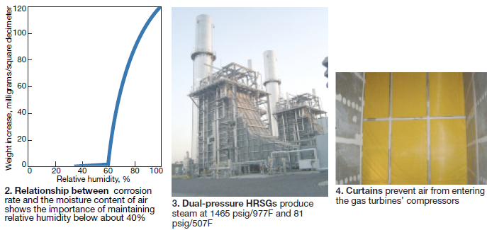
- Maintain relative humidity (RH) on the gas side of the HRSGs, and in the ST low-pressure (LP) section, at less than 40%. Fig 2, from a maintenance guide supplied by STG manufacturer Alstom Power, shows corrosion products are produced at an exponential rate when RH exceeds about 60%.
- Analyze and maintain cooling-water chemistry on a regular basis according guidelines provided by the tower supplier and GE Water & Process Technologies.
- Protect exposed surfaces by painting in accordance with recommendations from Lactec, a local technology institute and formerly part of Copel.
- Perform tests and inspections according to long-term shutdown procedures provided by the manufacturers and conduct preventive, predictive, and corrective maintenance as recommended in the plant maintenance manual. The foregoing activities must comply with environmental, safety, and health regulations and are facilitated by use of Copel’s computer-based O&M operations management system.
- Keep all space heaters for electric motors and generators on “automatic” when the equipment is not in service and check heater performance quarterly.
HRSGs, steam systems
Each of the plant’s two dual-pressure HRSGs (Fig 3) has a kettle boiler incorporated in the LP section. Its purpose is produce steam while removing heat from compressor discharge air used for rotor cooling. Araucaria’s dry layup procedures call for first draining the (1) water side of the boiler, including superheater, evaporator, and economizer panels; (2) HP and LP steam piping, (3) kettle boilers, and (4) the water side of the fuel gas heater.
Step two: Backfill those sections with nitrogen and pressurize the inert atmosphere to about 7 psig. Finally, check the concentration of oxygen in the inert atmosphere quarterly, bleeding and filling with fresh nitrogen as necessary. Albuquerque mentioned the desire to reduce nitrogen pressure to decrease its consumption. Copel is investigating the installation of more sensitive pressure gages for this use during layups, as well as the advantages of a nitrogen generator.
A plastic curtain closes off the air inlet to the gas turbine (Fig 4). Initially, a curtain also was installed at the stack entrance to isolate the HRSG but that has been replaced by a duct balloon, which is easier to deploy (Figs 5, 6). Dehumidifiers installed outside the HRSG (originally portable and installed inside) condition the space from the turbine inlet to the stack balloon to 40% RH. Space temperature and humidity are monitored via the DCS and alarms sound when limits are exceeded.
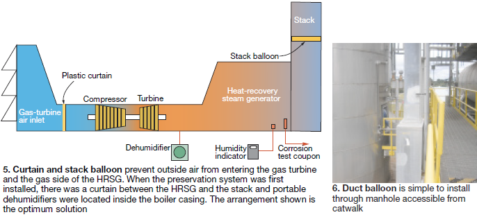
Such improvements have reduced dramatically the manpower requirements and time needed to install and break-down the preservation system. Specifically, the total effort now takes 25% or less time than was required originally, making the system viable for outages of about one month and longer.
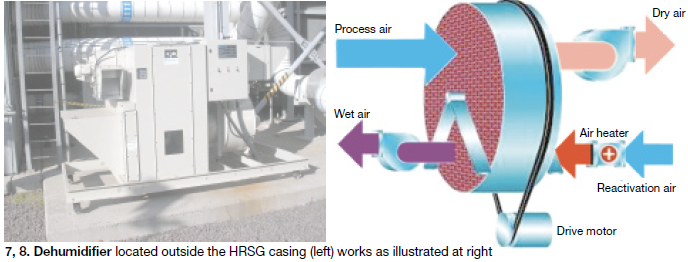
To illustrate: The plastic curtain at the HRSG outlet took four people 16 hours to install, including erection of the scaffolding required, and four people 12 hours to remove it. Two people can deploy the duct balloon in about an hour, and take it out of the stack with the same level of effort. Also, it originally took four man-days to install electric heaters and dehumidifiers inside the HRSG and another three to remove them. Both steps are avoided by use the permanently installed dehumidifier described in Figs 7 and 8.
Today the major effort in preservation system implementation is installation of the plastic curtain in the GT inlet, a task that takes two people about six hours to complete. Removal takes two people four hours.
HRSG and main-steam system fluid handling equipment operated or tested periodically are the following:
- Water-level control valves for the HRSG drums.
- Desuperheater spray-water valves.
- Blowdown valves.
- HP and LP superheater drain valves.
- Fuel-gas heater valves.
- All HP and LP steam-system valves.
- Blowdown-system sump pumps.
Gas turbine/generators
The preservation plan for the GTGs was based on the OEM’s recommendations, which proactively guard against corrosion. The inlet curtain and stack balloon described in the HRSG section are the first line of defense against corrosion. In addition, compressor bleed valves, manholes, inspection doors and other openings were sealed to prevent atmospheric air from entering the dehumidified engine. Any leakage through seals, walls, roof, doors of the GTC enclosure were repaired to prevent contamination by outside air.
The following equipment was tested or operated weekly, according to the test schedule developed for Araucaria, except where noted:
- Main lube-oil (LO) pumps.
- DC emergency LO pumps.
- LO vapor extractors.
- Turning-gear motors.
- Control oil pumps.
- Evaporative-cooler pumps (every other day).
- Compressor washing systems (monthly).
- Igniters (command test).
The plant’s valve test schedule called for periodic testing or operation of these flow-control devices:
- LO-cooler temperature control valve.
- Main-gas-line vent valve.
- Stages A, B, and C gas control valves (command).
- Pilot-gas control valve (command).
- Kettle-boiler air bypass valve.
- Coolant-flow control valve for disk cavities 2 and 3.
- IGV command.
- LP and HP compressor bleed valves (command).
- Instrument-air valve (command).
Steam turbine/generator
The 164-MW Alstom ST is comprised of HP and LP turbines arranged on one shaft. HP superheated steam flows through the former and into the latter, where it is supplemented by steam from the HRSG’s LP superheater.
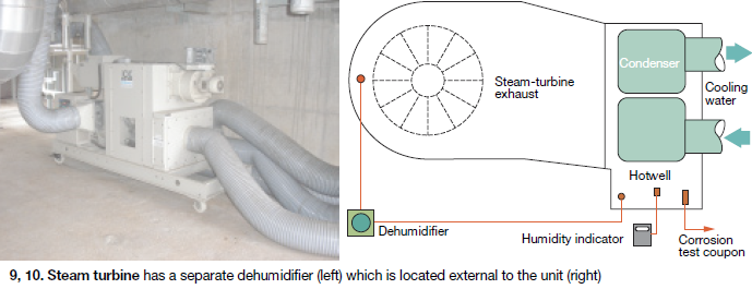
The condenser hotwell was drained in accordance with the OEM’s recommendations and the ST LP section originally was separated from the condenser with a plastic curtain like that used in the GT inlet. Reason for the curtain here was that the circulating water system had to remain in service to prevent wood members in the six-cell mechanical-draft cooling tower from drying out.
Heaters and dehumidifier were installed at the ST exhaust to keep the moisture level below 40% RH. Air temperature and humidity inside the turbine were monitored continuously.
As was done for the HRSG, a ST dehumidifier was permanently installed outside the LP section (Fig 9) and arranged as shown in Fig 10 to eliminate the need for installing/removing plastic curtains and the scaffolding needed to accommodate their installation and removal.
ST auxiliaries operated or tested weekly:
- Main lube-oil (LO) pump.
- DC emergency LO pump.
- LO vapor extractor.
- Turning-gear motor.
- Control oil pump.
- LO purifier pump.
- Gland seal-steam condenser exhausters.
- Jacking-oil pump.
Condensate system
The condensate system has two full-size pumps, preserved as follows with motor and pump coupled throughout the layup period:
- Pump pit maintained dry.
- Pump shafts manually turned twice monthly.
- Bearing lube replaced semiannually.
- Condensate piping from the pump to the HRSGs was pressurized to about 7 psig with nitrogen.
- Suction and discharge piping was drained monthly.
Valves operated or tested as part of the preservation program were the following:
- Condenser makeup control valve.
- Condenser rejects control valve.
- Condensate minimum-flow control valve.
- HP and LP steam-bypass desuperheater spray-water control valves.
- Spray-water control valve for HP steam serving steam seals.
- Steam-jet air-ejector hogging and holding valves.
- Spray-water valve in condenser neck.
- Fuel-gas-heater temperature control valves.
- Backpressure control valve for STG seal water to the STG vacuum-breaker valve.
Boiler feedwater system
Two full-size feedwater pumps are provided with each HRSG. Each pump transfers water from the LP section to the HP section and is equipped with an auxiliary LO pump.
The boiler-feed pumps were drained and suction, discharge, and recirculation valves opened. This allowed nitrogen in the HRSG steam/water circuit to inert the BFPs and connecting piping as well. Pump shafts were manually rotated quarterly as recommended by Sulzer, the pump OEM. The BFP auxiliary LO pumps also were exercised quarterly.
Auxiliary systems
Fuel gas system piping was drained, vented, and pressurized with nitrogen. Valves were tested periodically.
Instrument and service air systems remained in service during the layup. Use of the redundant compressors and dryers was alternated according to the Plant Equipment Test Schedule.
Closed cooling-water (CCW) system also remained in service and the use of redundant equipment alternated.
Condensate/feedwater chemical control system (amine and oxygen scavenger for condensate and phosphate for feedwater) was out of service and inspected and maintained according to the Plant Maintenance Program.
Steam and water analysis system remained in service with a continuous flow of demineralized water.
Demineralized water system was operated quarterly to produce boiler-quality water and maintain the normal level in the demin tank. All functions of all equipment in the two parallel trains were tested and verified—including demin-water production, rinse quality, regeneration, backwash, etc.
The circulating water system serves the surface condenser and CCW plate heat exchangers and provides quench water to the HRSGs’ blowdown systems. Operation of the 3 × 50% pumps was alternated to assure one pump was on at all times to keep the cooling tower’s wood members wet and to provide blowdown for the wastewater system clearwell. Operation of the six tower fans also was alternated weekly.
The raw water system remained in service to supply water to the GT evap coolers. Filter feed pumps and the filter backwash pump were run quarterly.
The wastewater system, including the sewage treatment system, operated continuously. The waste neutralization tank was operated quarterly (in concert with the demin water system), sump pumps and the oil/water separator whenever it rained.
Chemical feed system remained in service and chemistry was monitored daily.
Plant DCS and major equipment control systems were kept in service and exercised as recommended by the manufacturers.
The plant auxiliary electric systems, backfed from the grid, remained in service. The emergency diesel/generator also was maintained ready to enter service when required. ccj