


Control logic protects against unit trips when exhaust T/Cs fail in service
Best of the Best Award
Challenge. Exhaust thermocouples (T/Cs) are high wear items and fail for various reasons on Effingham County Power’s two 7FAs. Each of the GE gas turbines incorporated into the plant’s 525-MW combined cycle has 27 T/Cs for combustion control (Fig 1). Common root causes of the failures are high-frequency vibrations, cyclic fatigue, and improper installation. Eroded or disfigured T/C tips are typical telltale signs of the first two causes. Improper installation usually reveals itself as wear at the seating ring.

Despite procedures in place for proper installation of thermocouples, and an optimal tuning program, it still is common for T/Cs to fail on these engines. If one exhaust T/C fails, the unit is at risk of experiencing a controls-initiated trip with a subsequent T/C failure.
There’s also an element of risk associated with replacing exhaust thermocouples while the unit is operating. For example, if a technician disconnects the wrong T/C, or thermocouple wiring is inadvertently grounded during replacement, a spurious unit trip could occur. But Effingham typically cycles daily and an opportunity to change failed T/Cs generally exists at the end of each dispatch run.
Up until the end of last year, if a T/C failed with the unit in operation, plant operators would input a fixed forced value into the control logic until the thermocouple could be replaced. This process did not always provide acceptable results: When the failed input has a fixed forced value applied, the fixed value does not change with the process as might be necessary. The resulting difference between the running exhaust temperatures and the fixed forced values often caused an unacceptable spread—thereby creating a runback or trip.
When operating a 7FA with a failed T/C it could be difficult to manage the failed thermocouple by forcing fixed values—especially if the operator has limited experience, is preoccupied with a process upset, or has other tasks and responsibilities requiring attention. It does not take much time for a control process to upset the plant and create a trip, so a solution was created to remove the operator from having to continuously manage the fixed forced value of a failed exhaust T/C.
Solution. The long-term solution needed to manage failed exhaust T/Cs had to be something operators (1) could manually switch on and off, as needed, (2) would not require constant monitoring, and (3) could be used on multiple thermocouples, as necessary. The solution selected is simple and easy to use. Its main components are the following:
- Watch Window.
- Forced point to true or false.
- Graphic indication.
- Alarm generation.
The solution starts with a Watch Window within Toolbox. This Watch Window includes only two items for each exhaust thermocouple—a real point and a digital point. These two items are the point for the actual value of the T/C (real) and the point to force true or false (digital) tracking to the median value. There are 27 sets of these two points in the Watch Window; they are labeled 1 to 27 for identification.
The purpose of having the actual value of the exhaust thermocouple is for pre- and post-review of the failed T/Cs. The former helps in confirming the identification of the erratic or failed point, prior to forcing the point to track the median value. Benefit to having the post review is to confirm that the exhaust thermocouple is stable before removing forced tracking. The digital point is used to turn on and off the tracking to a median-value function for the exhaust thermocouple logic.
The logic is very simple and includes only a Boolean engine and a Select F block. The former is used to originate the digital point to turn on/off the tracking function. Boolean engine input is the point that is forced true or false to enable/disable tracking. The Select F block essentially is a switch that switches its output between the actual T/C input value and the median value when enabled to do so. These blocks function just after the real exhaust T/C input to the Mark VI logic, thereby preventing any other downstream blocks that use this point from being affected by switching to the median, or being affected adversely.
There is a graphic indication on the Cimplicity HMI located on the exhaust-thermocouples display screen that indicates if a T/C is tracking the median value. This indication is provided within the bar graph for the switched thermocouple: The background of the bar graph turns gray and stays gray.

There also is an alarm that indicates forcing is enabled for each T/C. It indicates which thermocouple is in alarm and that it is forced to track the median. It will not clear until the tracking is turned off. A written procedure has been developed to assist the operator. It also provides guidance on limitations for the number of, and proximity of, exhaust T/Cs that may be forced. Spare exhaust thermocouples are maintained in the storeroom and repairs typically are completed when a unit is shut down.
Results. Since implementing this solution at the beginning of the year, the plant has not experienced any runbacks or trips that can be attributed to failed exhaust thermocouples. The tool has added value by reducing the number of equivalent starts while also providing a means to reduce the likelihood of a unit trip during operation.
Project participant:
Michael A Sears Sr
Using designated equipment to transfer oil
Best Practices Award
Challenge. The plant uses several different types of oils for lubricating pumps and motors. In most cases, adding oil to this equipment involves volumes less than one gallon. For turbine sumps, cooling-tower-fan gearboxes, and circ-water pumps, larger quantities of oil are needed for lubrication.
In the past, equipment used to transfer larger quantities of oils were not labeled or controlled to minimize contamination by other types of oils or foreign material. The old transfer rigs consisted of Tygon® tubing and threaded pipe fittings. Hose clamps were used to attach the Tygon® tubing to the drum pump tube and threaded pipe fittings. This arrangement allowed the oil remaining in the hoses to seep out while being kept in the storage building, leading to safety and housekeeping issues.
Also, plant personnel discovered the Tygon® tubing would become brittle after extended use transferring the various types of oils used at the plant. Since the tubing becomes brittle and then is hard to handle, technicians then would use new hose for each evolution. The use of new hose and fittings increased costs to the plant.
The used hoses and fittings were not properly marked, therefore allowing the potential for cross contamination with each use. Preventing cross contamination was an onerous process requiring a technician to flush the hoses to ensure no foreign material or oil residue was present. This led to increased disposal costs with the number of flushes required.

Solution. The plant staff evaluated which oils typically are transferred in quantities greater than one gallon. The list was narrowed down to three different types of oils; the oil stored in the turbine lube oil sump, cooling-tower gearboxes, and circ-water pump motors. The decision was made to build two transfer assemblies to evaluate.
The first step was to determine the equipment necessary to transfer the oil from 55-gal drums to the component. Staff determined an electrically driven drum pump for each type of oil would best meet this specific task (Fig 2). Since the electric motor does not come in contact with the oil, only one motor was purchased.
The next step was to evaluate the equipment based on transfer rate and its compatibility to the oils they would come in contact with. Local vendors and industrial supply companies were contacted to solicit input on what equipment would best meet our needs to support the oil transfer process material at a competitive cost.
Once the equipment specifications were determined, the equipment was purchased. The drum pumps and motor are constructed from oil and chemical-resistant PVC. The benefit of selecting this material is that the assemblies are lightweight and easy-to-use.
Plant personnel contacted the local supplier of gaskets and hoses to determine the best material for the transfer hoses. They recommended a 1-in.-diam rubber hose based on its ability to handle oil and remain flexible for up to 10 years of service (Fig 3). This hose is also easy to handle and is compatible with several types of fittings, which could be used to connect the hose to the components and other lengths of hose.
There was one disadvantage to using this hose, since it has wire reinforcement in the material, hose clamps could not be used to attach the hose to the drum pump. The clamp needed to attach the hose to the drum pump discharge, could easily damage the PVC, so an alternative was needed.
The vendor of the hose suggested a nylon reinforced Tygon® tubing tailpiece be used on the discharge of the pump. This tailpiece is 12 in. long and has a hose clamp on the end that attaches to the pump and a cam lock fitting on the other to attach to the rubber hoses. The use of Tygon® minimizes costs and the fittings are reusable. This tailpiece forms a tight seal on the pump discharge and is connected to the pump at all times.
Finally, staff walked the plant to determine the necessary lengths of hose needed to transfer oil. Personnel wanted the hose lengths to be easy to handle and assemble. They also needed to be long enough to go from the drums to the components. The decision was to use 15- to 20-ft lengths of hose. On each end of the hose, a male and female cam lock fitting was installed with a cap or plug, as required.
The use of cam-lock fittings allowed for easy set-up and take down. The remaining oil in the hose will not leak out onto the ground, while transporting or inside the storage building when the plugs or caps are installed.
Since two drum pumps and four lengths of hose were purchased, staff had to assure the assemblies were used for the correct oil. Every fitting was painted either red or blue depending on the oil to be used. The storage tubes for the pumps and the racks for the hoses also were painted either red or blue. This color coded system would minimize the potential for cross contamination of the oils used.
Results. The system has been used on several occasions to transfer oil. The first benefit noted is the equipment is stored in a designated location. Since the hoses are used for a specific location or component, all the materials can be transported in one trip.
The use of cam lock fasteners allow for easy set-up and removal. With plugs and caps being used at each end of the hoses, the risk of oil leaks while in transit to work site or in storage has been reduced.
The plant purchased equipment and materials for these transfer assemblies that are designed to with stand the effects of oil and should be in use for a significant amount of time before requiring replacement. This new system will reduce future transfer equipment purchases and disposal costs.
Project participants:
Bob Kulbacki
Mark Gunter
Robert Scogins
Preventive damage measures for water-wicking cables
Best Practices Award
Challenge. Plant’s underground conduit is in continuous contact with water because the plant is only 75-ft above sea level. With rainfall averaging more than 40 in. annually, the conduit remains submerged.
While investigating a faulty transmitter, the 4-20-mA terminal block (HART) cover was removed and several tablespoons of water came out of the terminal housing. The terminal block was shorted out and destroyed because of the standing water inside the transmitter cover. Staff tried to find the source of the water intrusion. It was thought rainwater might be getting into the conduit. That was ruled out by completely sealing the conduit and the transmitter housing.
The issue recurred on occasion, each time the 4-20-mA terminal block shorted out or the housing held water. There was no source for the water 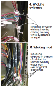 intrusion other than the cable itself.
It was decided to open up the closest conduit cover to the transmitter and cut a piece of the insulation back; water came out of the insulation proving that we had a wicking issue. Also witnessed was cable wicking in a few of the DCS system cabinets. The cabling in the cabinets seeped out a sticky white residue which covered the cables and the surrounding area (Fig 4).
Realizing this issue could eventually create a reliability problem, a proactive approach was employed to address conduit runs with known water intrusion. Drawings were used to research potential risk areas. In doing so we found several transmitters having the same wicking issue. Some of them had damaged terminal boards.
Solution. The solution led to removing the cable from the conduit at the transmitter and stripping back a six-in. section of the cable insulation a few feet from the transmitter. The cable end leading to the transmitter also was taped securely to prevent any further wicking (Fig 5). The cable was then placed back into the conduit. Where locations would allow, the conduits were modified with drains to protect against standing water.
The same cable procedure was used on the DCS system cabinets to prevent the sticky seepage from covering or damaging equipment. The cables were stripped of the insulation inside of the cabinet at floor level allowing the seepage to occur below the termination points and modules.
Results. Being proactive has prevented damage to the terminal boards on the transmitters leading to increased reliability. This measure has also prevented damage from occurring on the DCS system cabinet and modules.
Project participant:
Cheryl Hamilton
Observations program strengthens safety culture
Challenge. In order to drive the plant’s safety culture forward, personnel are encouraged to focus on leading, rather than lagging, indicators of safety. A near-miss reporting program is in place, but can be viewed as a lagging indicator of safety.
The staff agreed this program was not an effective tool for addressing safety issues. Also, management realized the possibility of near misses occurring that weren’t being reported. Members of the safety committee theorized that the lack of reporting was because the employees were reluctant to be associated with something with such a negative connotation, or they didn’t fully understand what constituted a near miss.
Solution. Staff addressed these issues by replacing the near-miss reporting program with a safety observations program. A safety observation is a potential hazard or incident that has not resulted in any personal injury or damage to property.
When an employee identifies a safety issue—a trip hazard, loose grating, fire hazard, etc.—he or she completes a short form which describes the finding and emails it to everyone in the facility (see examples). If possible, the employee fixes the issue on the spot, often providing before and after photos in the report. If the issue cannot be resolved immediately, a work order is written. The EHS specialist keeps a database of each safety observation and tracks any further corrective actions necessary.
During monthly safety meetings, the status of safety observations from the last meeting is reviewed and new safety observations are discussed. For each safety observation an employee submits, he or she receives an entry into a drawing for prizes such as tee-shirts, caps, or gift cards. The more safety observations the employee turns in, the greater the opportunity is to win a prize during the meeting.
Results. In 2012, which was the first year of the program, plant management received 57 safety observations. In 2013, that number more than doubled to 133. By comparison, in 2011, there were no near-miss reports.
This program empowers employees to take ownership of safety issues in the facility, and it also broadens their view of what constitutes a safety issue. Management believes this makes them safer employees. In addition, the program demonstrates management’s commitment to providing a safe workplace by tracking and reporting safety-related corrective actions back to employees.
The safety observations program takes something that many people consider negative—a near-miss—and turns it into something positive, competitive, and even fun. It is a proactive approach to safety in the workplace that raises awareness of safety issues, dramatically increases the communication of safety concerns, and further strengthens the safety culture within our organization.
Project participants:
Jobie Seward
Nick Bohl
Paul Garrett