


Make metallurgical analysis part of your maintenance program
By P. Lowden, S Turcott, and S Hastie, Liburdi Turbine Services
Deterioration of turbine blades, especially for cycling and peaking gas turbines, is a fact of life. To manage blade life, OEMs provide guidelines for maintenance intervals as well as repair recommendations. However, these guidelines are based on fleet analysis, and may not consider your site-specific operating conditions.
For this reason, you should consider incorporating metallurgical analysis (MA) of turbine blades into your maintenance program. It will help you optimize your service intervals, avoid component failures, make better maintenance decisions, and reduce costs (sidebar).
MA, or life analysis, allows complete characterization of the actual post-service condition of your blades—including material state, coating degradation, and damage to internal passages. Interpretation of the data allows you to assess repairability, determine the best repair processes, evaluate and select the best coatings, identify abnormal engine operating conditions, and assess the potential for a service interval extension (see table below).
MA techniques are well established. One blade is selected for destructive examination. Unlike stationary components, rotating blades experience the same gas-path temperatures and loading, so a single blade is considered representative of the entire set. Often a blade which exhibits irreparable damage can be selected so that an otherwise serviceable blade is not consumed by the analysis. The following steps are then taken: blade history review, visual examination, nondestructive testing (NDT), and surface-deposit collection.
Then the blade is sectioned to obtain samples from the lower, middle, and upper portions of the airfoil, the tip or shroud, or any other sections of interest. A section of the root is examined, too. It serves as a pre-service, as-new, material benchmark because the operating temperature of the root is below the material degradation point. Samples are then prepared and subject to microscopy and microanalysis techniques, along with mechanical testing of the base metal.
Creep damage and alloy aging
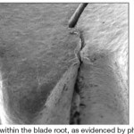
When new, the size, density, and morphology of the blade alloy are optimized for maximum strength. During operation at elevated temperatures, however, the alloy’s microstructure changes (Fig 1). Centrifugal loading and high temperatures cause (1) microstructural degradation of the airfoil material and (2) creep deformation, a diffusion mechanism correlated exponentially to temperature. Eventually, creep creates voids which link to form cracks (Fig 2).

Unless voids are already formed, it is difficult to detect creep damage. Mechanical testing can indicate reduced creep rupture life, since deterioration is caused by aging effects. Both creep and microstructural damage can be repaired, and material strength fully restored using appropriate heat treatments.
Because degradation is heavily influenced by temperature, the condition of the base alloy provides a thermal map of the blade’s operating temperatures. Once this thermal profile has been benchmarked for a given blade design, abnormal engine operation—such as short-term overheating, long-term overheating, and gas-path temperature profile shift—can be detected.
The condition of the base alloy also helps address the length of the service interval. Gross microstructural damage, or the presence of creep voids, suggests shorter service intervals; moderate base-alloy deterioration suggests service-interval extension.
Case studies illustrate value of metallurgical analysis
After a combined-cycle facility with four GE 7EAs had been uprated from 2020F to 2055F firing temperature, the engines experienced extremely rapid parts deterioration and the decision was made to return to the original firing temperature. Unfortunately, the parts deterioration persisted.
The standard deterioration rate at the original temperature was well documented, the plant having made life analysis of turbine blades standard practice for more than a decade. When the components operating at what was believed to have been the original firing temperature were examined, plant personnel concluded that they would not survive the full 24,000-hr service interval.
Metallurgical analysis (MA) showed that the blades actually were operating at temperatures higher than 2020F, so that the plant had not actually returned to pre-uprate operating conditions. Subsequent modeling showed that the exhaust temperature control curve had under-estimated the firing temperatures following the uprate. MA provided the operator with evidence of the incorrect firing temperature and the OEM ultimately corrected the control curves.
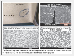 As a second case study, the blades of a Rolls Royce RB211-24G HP turbine were submitted for repair. The blades had 49,000 total operating hours, and 28,000 hours since the last repair. The engine had experienced a thermal spread condition. To avoid trips, several thermocouples were disengaged. Subsequent inspection of the blades revealed TMF cracks on the lower airfoil. Two blades were selected for MA.
Optical examination confirmed the damage to be typical of TMF (photos), but overall base-metal degradation was considered more advanced than for other blades with similar service hours. The area of TMF damage exhibited significant base-alloy degradation, indicating a relatively high operating temperature.
Such high temperature would result in large thermal variations during engine start/stops and reduced material strength, both of which would have contributed to thermal cracking. If MA had not detected internal TMF cracking, a repair shop would have risked basing repairability on external conditions alone.
High-cycle fatigue cracking
 Fatigue cracks can form from repetitive loading at moderate stresses. These cracks usually are attributed to vibrations, rubs, or resonant-frequency events. NDT can detect cracking but metallurgical analysis is required to show what initiated the crack (Fig 3) and whether the rest of the blade set can be repaired and how.
The crack may have started from an isolated cause (material defect, impact) or the entire set could be susceptible (for example, resonant frequency). Engine operating conditions can also be correlated to the cracking phenomenon.
Repairability will depend on the location, and the size and depth, of the crack. Fatigue cracks usually initiate on the external surfaces and NDT can determine repair recommendations blade by blade. Cracks at the root and the majority of the airfoil generally suggest that the blade be retired. If the entire blade set was susceptible to fatigue cracking, appropriate heat treatments can alleviate cyclic base metal damage and prepare the set for further service.
Thermal mechanical fatigue damage
Temperature gradients in blades are caused both by rapid changes in operating temperatures and changes in cooling effects at steady state. Resulting thermal stresses lead to thermal mechanical fatigue (TMF) damage.
Repeated cycling exacerbates low-cycle fatigue crack initiation and propagation, and usually is the life-limiting factor for engines with high start/stops and trips. Depending on the location, external surface cracking can be repaired but cracking on internal surfaces means the blade set should be retired.
External coating condition
Oxidation resistance of coatings is based on the coating’s aluminium content. Once the aluminium content is depleted below a critical value, the coating does not provide the same level of protection (Fig 4). Coating breaches occur if the aluminium coating is completely depleted or if TMF cracks appear (Fig 5).

Cross-section microscopic examination will determine the amount of aluminum remaining in a coating (coating remaining life) and the extent of cracking and oxidation damage to the coating and base alloy. For blade sets where the coating failed to prevent base-metal damage, the coating type, machine service interval, and operating conditions should be carefully reviewed.
Thermal barrier coating loss
The base metal of internally cooled blades is insulated from the hot-gas environment with thermal barrier coatings (TBC). In addition to the TBC, a “bond coat” is applied to the metal surface to protect against oxidation. Because the TBC coatings are porous, they are subject to spalling when a brittle oxide layer forms between the TBC and the bond coat, and then reaches a critical thickness (Fig 6). TBC degradation can also be initiated by impact damage. Close examination will determine the loss mechanism. TBC coatings are considered consumable by OEMs and performance is considered inadequate only if blade damage is irreparable.
Hot corrosion
Hot corrosion (Fig 7) accelerates degradation of the coating and base metal when contaminants such as sulfur, sodium and potassium salts, vanadium, and/or lead are present in the hot gas environment. Type I hot corrosion occurs above 1600F, Type II between 1200F and 1600F. Their damage mechanisms differ but implications and preventive measures are similar.
Seawater humidity is a common source of salts, and the other necessary contaminants (sulfur, vanadium, lead) are common in liquid and sour gas fuels. Sulfur also may be introduced to the air intake of the engine if a diesel exhaust is nearby. Coatings that provide hot corrosion protection are one solution, but the better one is to make sure filters are working properly and fuel specifications are being met.
Impact damage, airfoil deposits
Impact damage results from foreign objects impacting blades at high speeds. MA can assess the extent of the damage, both at the surface and below if the coating has been compromised. Inspection methods can be developed to distinguish salvageable blades from irreparable ones.
Deposits that build up on airfoils reduce efficiency and indicate an upstream issue. Indirect damage is sustained when cooling holes are blocked. Analyzing the composition of deposits indicate their origins. The deposits themselves generally do not affect the reparability of a blade set.
Internal surface condition
Damage to the base alloy of internal cooling passages cannot be repaired. Determining whether a set of internally cooled blades can be safely returned to service requires MA; NDT cannot detect most internal damage modes.
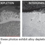
Uncoated internal surfaces.Alloy depletion can occur at the surface of uncoated internal surfaces. Base-alloy elements—such as aluminum and titanium—diffuse to the surface (Fig 8), leaving behind a depleted zone. As the depleted area grows, the base meal loses fatigue strength and effective wall thickness, important for mechanical loading. MA is the only way to determine the remaining effective wall thickness because it discounts the depleted zone. Forms of oxidation damage include intergranular oxidation (IGO) and stress-assisted grain boundary oxidation (Sagbo).
 Coated internal surfaces. Internal coatings behave similarly to external coatings with respect to degradation. Destructive microscopy is the only way to characterize the extent of internal coating degradation. Because of the high temperatures of some heat treatments used to repair the base alloy, the internal coating may have to be removed regardless of its condition.
Internal hot corrosion. This degradation mechanism is similar to external hot corrosion, but is usually identified as Type II because of the temperature regimes. Any significant depth of internal hot corrosion damage is cause for blade retirement.
Internal deposits. When blockage of cooling holes occurs because of internal deposits, local thermal degradation accelerates. Analysis will help determine the source. CCJ
