


Almost 25
It’s early October, so the 2015 meeting of the Western Turbine Users Inc (WTUI) likely is not on your radar screen. Mistake! Registration for the March 15-18 Conference at the Long Beach (Calif) Convention Center opens November 3; early registration for the 25th anniversary celebration is particularly important to assure a room at one of the conference hotels.
WTUI has been satisfying the technical information needs of LM aero owner/operators for more than a quarter century, reminds Treasurer Wayne Kawamoto, plant manager, Corona Cogen, who has participated in the organization’s meetings since before incorporation in 1991. The annual conference and expo has hosted more than 1000 participants for each of the last few years and is expected to break the all-time attendance record in Long Beach.
The go-to location for all conference information is www.wtui.com, where you can register for the meeting, book exhibition space, and connect directly with hotels for reservations.
Special technical presentations
CCJ’s coverage of the 2014 Western Turbine meeting continues below (previous installments in 4Q/2013 and 1Q/2014) with a review of three special technical presentations that address non-engine topics of interest to aero owner/operators. The editors selected the following three presentations from the Palm Springs conference for expanded coverage:
- “HRSGs in Flexible Operation,” Ned Congdon, PE, HRST Inc.
- “Recent Developments in SCR and CO Catalyst Systems,” Dan Ott, Joe Otto, and Ted Heron, Environex Inc.
- “Fuel and Water Valve Maintenance,” Wade Burdick, Woodward.
PowerPoints for three more special technical presentations are available (to users only) at the group’s website.
Fast starting of combined cycles is a hot topic today because having that capability in certain markets enables power producers to maximize their revenue opportunities. HRST Inc’s Ned Congdon, PE, incorporated fast starting into his presentation on flexible operation of HRSGs. He began his remarks by stating the goals of a fast-start program:
- Enable rapid loading of the gas turbines.
- Provide steam to the steam turbine at the proper flow rate and temperature.
- Avoid damage from thermal stress and overheating, and preserve reliability.
- Avoid corrosion.
Congdon then reviewed how legacy HRSGs in service may restrict or limit the plant startup rate and discussed possible upgrades to reduce the amount of time it takes to bring a combined cycle online. He discussed the damage that can be done by desuperheater overspray, the advantages of purging the gas side on shutdown rather than on startup, how to control steam drum level on startup, piping arrangements that match boiler HP steam temperature to turbine requirements, and how to reduce HP drum stress.
The boiler expert focused on the importance of steam sparging, HP-drum temperature ramp rate, and layup considerations in reducing startup time with minimal impact on the lifetime of pressure parts. Here’s a summary of what he said:
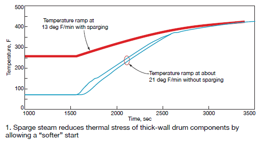
- Steam sparging. One of the simplest ways to minimize the risk of drum cracking is by carefully controlling startup and shutdown temperature ramps within OEM guidelines. Cold starts can be particularly stressful, but steam sparging can mitigate those effects by keeping the drum warm and pressurized while the unit is offline (Fig 1).
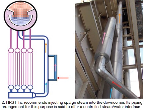
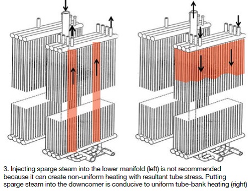
Congdon recommended that sparge steam be injected into a flowing fluid to prevent water hammer and suggested a downcomer location to promote reverse flow in that circuit. Some HRSG designs have a simple welded connection for this purpose, but HRST uses the arrangement shown in Fig 2 to better control the steam/water interface. Congdon advised against injecting sparge steam into the lower manifold or lower headers because the temperature of the water flowing to all tubes would not be the same (Fig 3). The result could be damaging thermal stresses.
- Control the HP-drum temperature ramp rate independently of the gas-turbine startup rate by venting steam. In some cases this may be easier said than done, because additional vent and/or bypass capacity might be required. Recall that the volume flow of relatively low-pressure startup steam is greater than the volume rate of flow at design steam conditions. Thus physical changes to condenser and/or sky vent arrangements based on design steam conditions may be necessary. It is important to review condenser thermal performance and capacity for startup flows; vent valves as well, recognizing that most vents are designed for short-term full-load reject.
- Lay-up best practices. Prior to shutdown, Congdon told the group, to (1) conduct several short intermittent blowdowns to eliminate solids; (2) raise the drum level to minimize nitrogen consumption; (3) eliminate leakage from vents, drains, and block valves to the degree possible; (4) maintain operating water chemistry—AVT-O, for example—during shutdown; (5) inject nitrogen near 0 psig. For prolonged wet lay-ups, provide the capability to recirculate water in the boiler and to sample boiler water periodically to maintain the desired chemistry.
The boiler expert offered the following advice for minimizing the rate of cooling of pressure parts during short-term lay-ups:
- Install a stack damper and insulate the breech/stack. They are your best defenses against heat loss. Keep in mind that low-emissivity stack paint, although a less-effective alternative than insulation, is much less expensive.
- Drums reach 0 psig at different times and, therefore, may require nitrogen additions at different times. A system that automatically injects nitrogen based on a drum pressure signal might be a worthwhile investment.
Long-term layups benefit from steam sparging. Keeping the HP drum warm reduces the thermal stress of thick components (such as the drum wall), as well as the time it takes for a cold start. Steam sparging also heats the gas side, lowers relative humidity, and helps avoid freeze-up. The potential risks of steam sparging are water hammer, diluted cycle chemistry, and thermal stresses if done incorrectly.
Proper gas-side layup is important because HRGSs can deteriorate more rapidly out of service than when they are operating. Take steps to avoid corrosion of gas-side components when the unit is shut down, thereby reducing the stack rust plume during the next startup and minimizing the increase in gas-turbine backpressure from tube fin fouling. Preventive steps include keeping rainwater and humidity out of the HRSG with good roof seals, installing a stack damper, and considering addition of a gas-side dehumidifier. During inspections, pay particular attention to material wear and tear near roof and floor pipe penetrations and tube fins.
Team Environex was invited by the Western Turbine steering committee to speak about recent developments in CO and SCR catalyst systems for aeros. The focus of the presentation by Dan Ott, Ted Heron, and Joe Otto was on the following areas:
- SCR/NOx reduction:
+ Impact of Inlet NOx concentration.
+ Ammonia distribution and ammonia slip.
+ Startup emissions.
- CO oxidation:
+ Catalyst plugging and platinum migration.
+ Low-temperature operation and sulfur contamination.
+ Rejuvenation.
To get everyone in the room “on the same page,” the trio reminded that the optimal operating temperature for SCR catalyst is between 700F and 750F, but that its location in most combined cycles generally is in a region of the heat-recovery steam generator where the exhaust-gas temperature ranges from 550F to 650F. For simple-cycle units, exhaust-gas temperature at the catalyst location typically is between 750F and 900F. Optimal operating temperature for CO catalyst, most often located upstream of the SCR ammonia injection grid, is above 800F.
It’s important to monitor SCR inlet NOx to assure meeting emissions expectations, the experts said. You should be at 15 ppm inlet NOx if your goal is to achieve 2 ppm NOx at the stack with only 2% ammonia slip, as some regulations require. Rules of thumb to keep in mind:
- Ammonia slip increases with inlet NOx.
- Ammonia slip limits NOx conversion efficiency.
- Reducing inlet NOx can decrease ammonia slip and increase catalyst life.
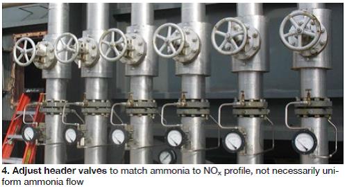
- Proper ammonia distribution is critical for achieving high NOx conversion (90+%).
- Frequency of ammonia tuning depends on the NOx conversion requirement.
A case study was presented to show the value of ammonia tuning. The example, for a simple-cycle LMS100, revealed that 90% NOx reduction was required to achieve the 2.5-ppm stack NOx limit given 25 ppm NOx in turbine exhaust. The stack ammonia limit was 5 ppm, less than the 7 ppm reported by the CEMS to achieve the required 90% NOx reduction. Tuning brought stack ammonia into compliance (Fig 4).
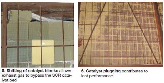
Ongoing maintenance of the catalyst bed was stressed. When exhaust gas bypasses the catalyst bed both stack NOx and ammonia increase. If you get a bad CEMS report, be sure to inspect the catalyst bed for top and side seal damage and for the shifting of catalyst bricks (Fig 5). Catalyst collects particulates over time, contributing to an increase in backpressure. Remove the build-up by vacuuming periodically (Fig 6).
Leeway given on startup emissions by regulatory authorities is disappearing and this can present challenges. More catalyst may be required to act as a sponge for NOx produced early in the operating cycle, when design operating temperatures have not yet been achieved.
Also, keep in mind that ammonia slip increases as catalyst ages. Near the end of life, slip increases exponentially as catalyst deactivates—so-called ammonia “breakthrough.” If your monitoring of ammonia slip reveals a relatively small but increasing value over time, particularly when the catalyst is young, double-check to be sure inlet NOx is not off-spec. The catalyst may be blameless.
Plugging of CO catalyst can bias ammonia flow to the downstream SCR and contribute to increases in stack discharges of NOx and ammonia. Curves of CO catalyst performance shown by the presenters illustrated that oxidation “lights off” (speaker terminology) as temperature increases. The slope of the oxidation curve is near vertical with fresh catalyst as the exhaust-gas temperature ramps from about 175F to 350F. CO oxidation goes from 0% to more than 80% within that temperature regime. Fouling shifts the maximum potential CO oxidation downward, while poisoning/deactivation increases the minimum temperature needed to achieve the design CO conversion.
The presence of sulfur in the exhaust gas has a negative impact on the performance of oxidation catalyst, the speakers said. Acid washing of the catalyst improves performance. Onsite rejuvenation services are available. Keep in mind that CO catalyst contains valuable Platinum Group Metals and recycling can reduce the net cost of new catalyst by 25% or more.
Fuel and water valves. During his one-hour workshop on fuel and water valve maintenance, Woodward’s Wade Burdick addressed field issues, maintenance and overhaul, product obsolescence, and upgrade options for several of the company’s LM6000 and LMS100 products. What he had to say was important to this group because Woodward equipment is found on most engines in the LM aero fleets. To illustrate: The company has shipped nearly 3000 of its popular 3103 and 3171 gas valves equipped with EM35MR actuators over the last two decades. LM6000 O&M personnel are very familiar with these components.
LM6000. The product-line manager shared reliability data with attendees. For the EM35MR-actuated valves noted, Burdick said the company had only eight warranty returns from January 2012 until the WTUI meeting in March 2014; nearly 450 units had been shipped during that period. Interestingly, technicians could find no problem with three of the returns. Resolver feedback and motor errors accounted for the five issues confirmed.
Maintaining the reliability designed into any product rests on the user’s shoulders—for the most part. This generally requires relatively little effort. For the EM35MR/3103 or 3171, the speaker recommended annual offline full stroke of valve/actuator using the driver interface or service tool to verify smooth operation. Also suggested was removal of the motor and resolver covers to inspect for general condition and water ingress.
Every 50,000 hours or six years, these valves should be returned to Woodward for overhaul. However, Burdick said maintenance cycles might actually be shorter given the specifics of the application environment. Cycle length is impacted by fuel quality, ambient environment, valve cycles, operating modes, and other variables. Of particular importance, he added, is to protect the valve during water wash and turbine cleaning; more than one-third of 3103 gas-valve returns are attributed to water ingress. Do not pressure wash or submerge these valves in water, he stressed.
Burdick recommended that attendees read Woodward Application Note 51424 for an update on driver software and for improvements in the protection of the actuator motor against gear-tooth wear. The latter usually can be maintained within expectations by better managing valve cycles, employing a motor power cutoff, and periodic gear-train lubrication.
The reliability figures presented for Woodward stop valves mirrored those for the 3103 and 3171 gas valves. Excessive seat leakage was the problem identified with nearly half of the warranty returns. Burdick suggested offline stroking annually to verify travel time and yearly offline checking for seat leakage if not standard during startup. Periodic overhaul recommendations are the same as those mentioned previously. In addition to protecting stop valves against water ingress, the speaker said they also should not be exposed to reverse differential-pressure events; they can damage the main seat seal.
Annual maintenance recommended for EML 100/3151 water metering valves on the LM6000 was the same as for the gas valve discussed above, plus rotation/maintenance of the cavitation sleeve. No new service bulletins have been issued since 2010. Recommended overhaul for these flow-control devices is at least every six years or 50,000 hours. Valves should be protected against freezing.
LMS100. Burdick began with the fuel system, noting that both the SAC (single annular combustor) and DLE (dry low emissions) combustion-system alternatives for this product line use Woodward’s large electric linear actuators on various fuel valves. Recommended annual maintenance includes re-greasing the gearbox for each actuator according to guidelines presented in the O&M manual. The speaker reminded attendees that the shaft resolvers are set as alarms, not shutdowns. He also warned about the pitfalls of using the actuator/valves as steps or ladders.
Burdick discussed the dynamic updates to VBV (variable bleed valve) software performed in 2013, noting the possible need for more frequent overhaul cycles because of them. Suggestion to users: Have one or more spare actuators onsite to minimize downtime.
Service letter LMS100-14-003 provides guidance on how to inspect the VBV system. If your inspection reveals no separation/relative motion, operate the unit; if not, do not. But call GE and Woodward for suggestions on what to do next. Woodward now has field service teams available to inspect and correct all VBV system; call the manufacturer to schedule an appointment.
Controls upgrades
There’s never enough time at any user-group meeting to cover all subjects of interest to the membership. Today, a topic of considerable importance to gas-turbine owner/operators in general, and LM6000 users in particular, is the upgrade/replacement of ageing control systems. The LM6000 product line, introduced two decades ago, has been equipped with several different control solutions over the years—a couple more successful than others.
Upgrading and/or replacing legacy controls typically is motivated by one or more of the following:
- Some critical building blocks for the legacy systems are no longer supported by manufacturers.
- Inability to satisfy today’s NERC Critical Infrastructure Protection requirements.
- Challenged to meet grid requirements for reliable 10-min starts.
Designing a control system for the LM6000 and other aero engines generally is considered a more challenging assignment than it is for most frame GTs and steam turbines. The editors were able to identify only four companies that had provided replacement control systems for the LM6000 consistent with today’s demanding reliability and flexibility requirements: EthosEnergy (formerly Wood Group GTS), GE, Emerson Process Management, and Woodward.
EthosEnergy. Over the past five years, the company has executed more than 20 LM6000 controls upgrades on PA engines, PA-to-PC uprates, and on PC packages manufactured by Kvaerner, IHI, Stewart & Stevenson, and GE. EthosEnergy has proven experience upgrading Woodward NetCon (with and without remote I/O), Woodward MicroNet, and GE Mark V-LM and Mark VI Millennium panels. Upgrades include gas and dual-fuel machines, units with and without IGVs, EFS, and Sprint/eSprint units.
It has completed upgrades where the scope is limited to the turbine control, as well as at sites with extended scope, including: voltage regulator, power-system stabilizer, vibration monitoring, all-electric fuel- and water-valve upgrades, local and remote HMIs, and instrumentation. All of EthosEnergy’s LM6000 control upgrades have been executed as turnkey contracts, illustrating the company’s focus on providing a complete engineered solution that integrates seamlessly with the existing package.
EthosEnergy’s LM6000 open-platform solution, based on the Rockwell Automation PlantPAx platform, has been engineered as a direct replacement for the OEM control systems and accommodates various packaging arrangements. The typical solution installs within the existing control-room cabinet lineup along with the MTTB and MGTB where applicable, with a complete control-panel replacement option available to customers with Mark V controls. Standard core software and pre-engineered “building blocks” are used to maintain consistency and quality while providing flexibility.
GE’s aeroderivative Millennium units were introduced as the calendar approached 2000, a time when the need was to have an engine-qualified control system using the Mark VI™ platform with a high degree of standardization. Most Millenniums were Mark VI packages for engine/turbine control, interfaced with GE’s Fanuc 90-70 PLC for package control. More than 250 of these systems were produced at the turn of the century.
The Mark V control system was GE’s second generation of microprocessor-based turbine control configured as simplex and triple redundant. More than 3300 systems were shipped from 1991 to 2004. Most systems are still in service and supported by GE.
However, these solutions have reached the later stages of their lifecycle. The Fanuc 90-70 controllers and their associated I/O entered the last stage of support in 2011. GE continues to support the Mark V and Mark VI systems with parts and services, but these are limited in comparison to today’s level of technology.
Improving upon reliability, flexibility, availability, usability, and maintainability, GE introduced the Mark VIe control platform. The company offers special retrofit packages for the Millennium and Mark V controls that involve an upgrade to Mark VIe at less cost and with less disruption to operations than most customers might imagine, says the OEM.
The Mark VIe expands control capabilities and provides a common architecture for fuel and package control. It also follows a new and improved lifecycle model, with modular design also simplifying the modernization and maintenance process.
GE’s migration offering for the Millennium and Mark V packages is a new process for upgrading legacy systems to the Mark VIe control platform. Instead of performing a complete replacement of the existing control system, the upgrade is made through a simple plug-and-play exchange of critical electronics.
A GE migration is said to demand less downtime, impact, and risk to operations compared to traditional upgrade solutions. A migration solution is more than just a hardware and software product replacement or upgrade: It is a coordinated process that combines all the elements required to deliver the solution that meets the customers’ operational needs.
GE said it has performed more than 150 migrations for the Mark V, the majority on heavy-duty gas turbines. Most of these projects were completed in five days, “breaker to breaker.” A Mark V migration to the Mark VIe can be done, and has been, in as few as three days.
Emerson. A user presentation during one of the LM6000 Breakout Sessions at the 2014 Western Turbine meeting offered guidance for others planning a controls retrofit, based on experience gained at a four-unit peaker site. The LM6000PC engines there each had accumulated about 1500 starts and 8000 operating hours since commercial start in 2000. Objectives for this control-system replacement project included the following:
- Improve safety and operational reliability consistent with current industry standards.
- Maintain NERC CIP compliance.
- Reduce the number of control-system platforms in the plant and across the fleet.
- Improve alarm management.
- Initiate the development of advanced predictive diagnostics for engine monitoring.
- Eliminate startup exhaust-temperature spread trips.
- Provide for 10-min startup.
The user presenting spoke positively regarding his company’s relationship with Emerson. He said the utility’s input was accepted from Day One and progress reports were submitted for review on a regular basis. Concerning the former, several hardware and network changes were made—including the relocation of MGTB and MTTB I/O modules, network switches, and relay modules. Network security changes were implemented as well.
GT and BOP controls were commissioned in parallel. Commissioning teams included one person each from the utility, the control-system supplier, electrical contractor, and constructor. Every I/O point was checked from the field device through to the operating graphics; every analog point was checked with a signal generator at the field device.
Commissioning started with construction turnover on October 22, 2013. GT1 was operational November 9, GT4 a week later, GT2 the following week, and GT3 on December 12. Remote starting of Units 1 through 4 was tested successfully December 13. CCJ