


How to replace a Kato brushless exciter on a 9A4 generator

Green Country Energy
Owned by J-Power USA Operated by NAES Corp
801-MW, three gas-fired 1 × 1 7FA-powered combined cycles located in Jenks, Okla
Plant manager: Danny Parish
Challenge: Removing and replacing an exciter during peak demand period while limiting financial impact.
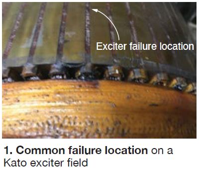
The GE 9A4 generator married to one of Green Country Energy’s three steam turbines experienced a ground-fault trip in August 2019, placing it into a forced outage. After removing the exciter stator, staff determined visually, and through testing, that the rotating field winding had shorted to ground (Fig 1).
Locating documentation, specialty parts and tooling, and qualified field technical advisors on short notice for removal of the rotating field was a daunting task. Although inspection and maintenance of the plant’s Kato exciters had been performed routinely (including removal of exciter stator), removal of the rotating field was not something GCE personnel had done previously.
Solution. Staff contacted other facilities to discuss exciter rotating-field removal/replacement experiences. While some plants had successfully removed the exciter rotor in the field, others had experienced complications that led to complete generator field removal and offsite repairs. GCE staff knew that pulling the complete generator field would result in a minimum of three weeks of lost generation and forced-outage hours, as well as additional risk to the generator.
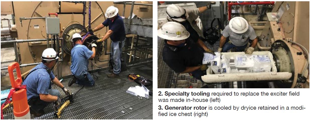
Upon reviewing the Kato documentation, drawings, and specialty tooling requirements, GCE’s maintenance, IC&E, and operations teams were confident this was a task they could perform onsite. After careful review with plant management, the owners (J-Power USA), and the NAES engineering department, GCE opted to manufacture its own specialty tooling for exciter-field removal and installation. This in-house-produced tooling (Fig 2), together with unique work processes, allowed plant personnel to remove the rotating field in less time than possible with a vendor-supported effort.
The 9A4 Kato brushless exciter historically had performed well at GCE with only minor issues. Because of the component’s long-term dependability, the plant did not maintain a spare. Kato no longer manufactures these brushless exciters and finding a replacement on short notice proved very challenging. While GE did locate a new old-stock replacement overseas, it would have taken weeks to deliver it to the site.
During the tooling manufacturing process, GCE’s management team reached out to other facilities with similar exciter arrangements. It located a new old-stock replacement at a partner facility that had experienced similar problems with its exciters and had purchased a spare. The partner facility sold GCE its spare exciter.
The extended lead time required to purchase a new exciter from the OEM (more than three months) encouraged GCE to have its original exciter rewound and shipped to the partnering facility. This gave both plants relatively quick access to a spare if needed. GCE then purchased a new exciter and had it shipped to the partnering facility; the rewound spare was returned to GCE.
Upon receiving the new exciter from the partnering facility, technicians verified its fit to the generator rotor and devised a system to shrink the rotor while expanding the exciter field. This enabled an appropriate “slip-fit” of the exciter field on the generator rotor.
Technicians retrofitted a very large ice chest to hold both the generator rotor end and dry ice to facilitate fit-up (Fig 3). The rotor was left on ice for around six hours. During rotor icing, the exciter field was heated with an external source. Technicians finalized the fabrication of an installation plate and extended deep sockets needed for the all-thread that was used for pressing the exciter field onto generator rotor.
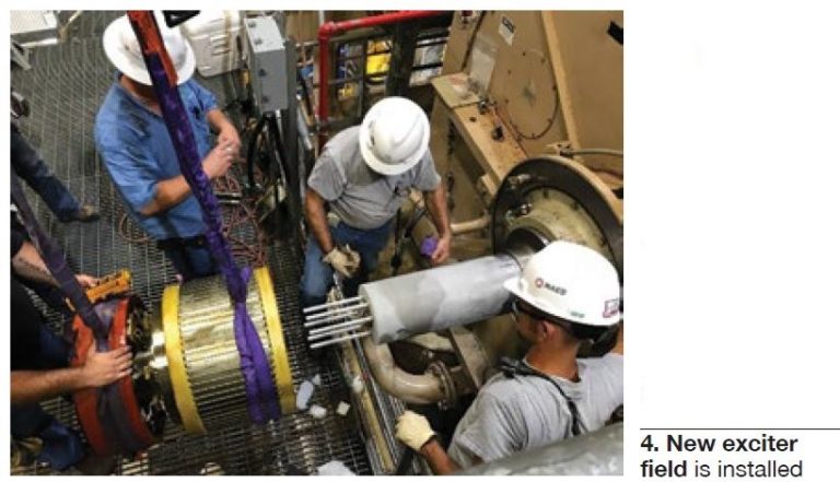
Results. A successful exciter-field replacement (Fig 4) was performed completely in-house in a relatively short period of time. In-house technical skills together with support from owner J-Power USA, operator NAES, and GCE management enabled timely project completion. The GCE team came together with a “We’ve got this” attitude and was able to gather the information needed through manuals, drawings, and collaboration with other facilities to fabricate everything required to remove and reinstall the exciter field.
In addition to the in-house technical skills, the relationships that GCE has cultivated through the years with other facilities allowed for productive and quick information exchange. These relationships also have led to equipment-sharing support. It was this support, along with the in- house technical “can do” attitude that took a potential three-week-plus outage, during peak season, and reduced it to six days. The positive impact to availability and generation was substantial.
Project participants: The Green Country Energy O&M staffs
Safe entry into gas-turbine compartments equipped with CO2 fire protection systems
Challenge. Safety is a core value at Green Country Energy and identifying opportunities for safety improvement projects is a big part of what GCE employees do daily.
Entering gas-turbine packages protected by CO2 fire suppression systems has always had inherent risks: The potential exists for an employee to enter a compartment and be present during a CO2 release. Technicians routinely enter GT compartments for inspections and other tasks.
During the early years of operation, CO2 fire suppression was not a requirement and was not installed in the exciter and/or load compartments. Through discussion with the insurance provider and other facilities, it was determined that adding CO2 fire suppression to these areas would be an industry best practice. This project was completed several years ago.
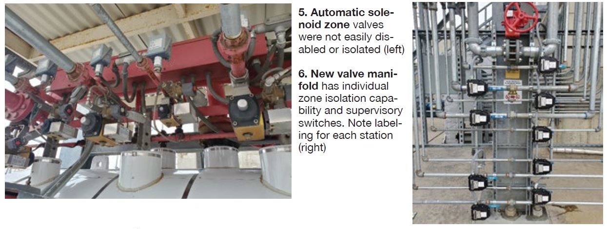
While addition of CO2 fire suppression in the exciter and load compartments provided needed protection against fire, bringing the extinguishing systems up to NFPA 12-2018 standards required manual isolation valves with supervisory indication for each zone. These valves were not installed at GCE because system isolation was not standard practice except in times of unit outages and individual zone isolation was not something that could be done easily (Fig 5).
Therefore, past practice allowed employees to enter exciter compartments and accessory modules for routine tasks without isolating the CO2 system.
The belief was that the audible and visual alarms, coupled with the time delay of the CO2 discharge, would give an employee ample time to evacuate the area. Although true, this left room for error and required complete system functionality to work. GCE technicians needed a way to safely perform routine rounds and readings in exciter compartments or accessory modules without the risk of asphyxiation from a CO2 release.
Solution. In 2019, GCE completed all GT CO2 fire suppression upgrades. The upgrades consist of CO2 manifolds with manual isolation valves for both initial and extended discharges to each zone (Fig 6). Valve supervisory switches also are used for remote valve position indication. Addition of manual isolation valves and supervisory switches, brought GCE’s CO2 fire suppression system up to current NFPA standards.
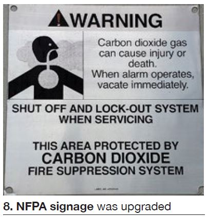
Lab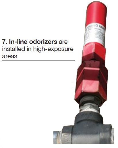 eling was added to the valves and piping to ensure correct zone isolation when used. Technicians can now easily isolate one zone (five total) without sacrificing the protection to other critical gas-turbine areas. Although not required by NFPA on systems with audible/visual alarms, odorizers were used in the high-exposure areas of the exciter and load compartments (Fig 7). Signage also was upgraded to current NFPA standards (Fig 8).
In addition to the equipment upgrades, a standard operating procedure was developed for all employees. The SOP does not replace tasks that would require a LOTO, but covers entries for readings and inspection. The procedure includes control room notification for isolation, restoration, and logging requirements.
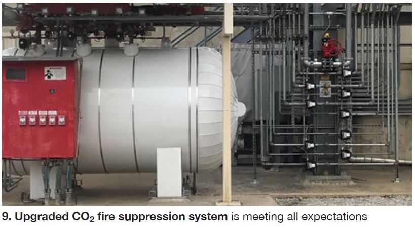
Results. The system and procedure have only been in place a short time but are working extremely well (Fig 9). The valve manifold allows for effective and easy isolation of fire protection zones. Technicians are now safely entering exciter compartments daily for readings and inspections. Although used daily for exciter compartments, this same process allows for quick access to accessory modules and gas compartments.
Project participants: The Green Country Energy O&M staffs