


By Steven C Stultz, Consulting Editor
The eighth annual meeting of the Air Cooled Condenser (ACC) Users Group, held Oct 3-6, 2016 in Dallas, offered a tailored agenda based on previous participant feedback. The content recognized the seasoned combined-cycle professional, but also addressed those perhaps newer to the industry attending to absorb fundamentals along with up-to-date experiences and achievements.
Day One in Dallas began with three tutorials capturing the essence of the overall program:
- Chemistry and corrosion.
- Design and performance.
- Operation and maintenance.
Interestingly, many of the fundamentals attracted insightful comments and discussion threads by even the most seasoned veterans.
“We make every effort, each year, to adjust to the industry [and its people],” said ACC Steering Committee Chairman Dr Andrew Howell, senior systems chemist, Xcel Energy. “We know the industry is in transition, and we know that both the depth and breadth of ACC experience are expanding quickly. We will stay at the forefront and provide both education and discussion for both repeat and first-time participants.”
One point stressed repeatedly was based on a good understanding of the fundamentals, but equally (if not more) importantly on in-depth awareness of ongoing and expanding operating experience. That point: Chemistry of the ACC controls chemistry of the generating unit.
Day One
Chemistry, corrosion
Dr Barry Dooley was first at the podium. Recognized internationally for his expertise and commitment to cycle chemistry, with a particular emphasis on flow-accelerated corrosion (FAC), the senior associate at Structural Integrity Associates Inc, presented a comprehensive review of steam-cycle chemistry and ACC internal corrosion. This launched the first tutorial.
Meeting participants listened carefully as Dooley, a member of the ACC Users Group steering committee and executive secretary for the International Association for the Properties of Water and Steam (IAPWS), traced operating experience and research history through specific sites in South Africa, the US, and Australia.
South Africa is where researchers began to quantify chemistry impact on specific areas (tube entry, for example). This helped identify specific issues beyond just knowing that this was a two-phase environment. Cross-members were reviewed which increased understanding (liquid-droplet contingent).
As the amount of data collected increased, a plant in Queensland showed that “some OEMs do not communicate on cycle chemistry needs. Within short operation at this plant, high levels of damage began to appear. We learned specifically that pH levels impact iron throughout the cycle,” Dooley said.
Dooley’s experience gave full credence to meaningful summary statements, such as these:
- ACC chemistry and corrosion issues are the same worldwide, regardless of unit manufacture, size and chemistry.
- Focused research began about 2007, but uncertainty was high and we knew it.
- We know now that compound turbulence is the main concern for ACC tube entry areas. For tube entry inspection, color is important and can be confusing, but clearly indicates the two-phase activity.
- Internal inspection is critical because tubes rarely are removed for laboratory inspection.
The ACC “controls” unit cycle chemistry, the speaker continued. A decade ago, international guidance was not available on this. Work since undertaken by IAPWS, in particular its publication of technical guidance documents, has provided much needed advice to plant operators.
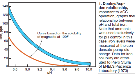
Dooley next explained the development of the Dooley/Aspden relationship for pH control of the ACC. In summary, they found that total iron versus pH was consistent worldwide (Fig 1).
Further characterization became available with the Dooley Howell ACC Corrosion Index (DHACI), allowing standardized investigation and tracking for both tube inlets and lower ducts. More specifically, the index evaluates and describes concerns in both the upper and lower sections of the condenser. It is now is used globally to identify and monitor ACC condition, and allows for comparisons worldwide.
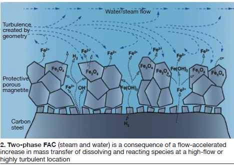
The essence of damage, according to Dooley, is the dissolution rate and impact on the directly related inner ferrous hydroxide (Fig 2). “But did we understand the environment, the mechanisms, and the proper prevention?” The answer: No, and still not yet. Studies continue as various solutions are applied.
As Dooley explained, “the key is understanding phase-transition-zone environments. The low-pressure turbine environment is thoroughly characterized, and this is the starting point for the ACC environment.
The solution, says Dooley, is dependent on removing the saturation of iron oxide Fe3O4 at the surface and precipitating it adjacently. The bottom line: Damage takes time (months or years) to repair. The best operating target is less than 5 ppb iron and pH great than 9.8.
He followed with an update (status) on film-forming products, and some initial trials to use these products to repair FAC damage. This is a long-term topic from last year’s meeting, and will be ongoing. One specific technology was presented during the meeting and is reported below in the section on film-forming agents.
“We are still looking for answers,” said Dooley. “The only source of complete knowledge is experience.” Specific international guidelines were then discussed for ACCs and two-phase flow with reference to the IAPWS technical guidance documents.
Air flow management
Sander Venema, Howden Netherlands, followed Dooley with a presentation on air flow management. It reviewed fundamental definitions and fan laws: system resistance (pressure drop); fan performance definitions (aerodynamic power, air volume rate, fan pressure rise); and both total and static efficiency.
Fan performance details covered system and fan curves, operating points, stability, and stall points. For a refresher, access Venema’s slides at www.acc-usersgroup.org (click the “Presentations” button). Application basics included fan diameter, type, number of blades, pitch angle, and operating speed. “The most easily adjusted parameters,” said Venema, “are pitch angle and speed.”
Pitch angle was covered in detail, comparing static pressure to flow and stall. One summary: increasing the blade angle will increase air volume flow, but will also increase fan shaft power, decrease pressure margin, and increase stall risk. “It will reduce fan efficiency, increase noise, and influence mechanical dynamics that should be discussed with the fan manufacturer,” he noted.
Speed was then discussed through fan scaling laws (scaling of air volume flow rate) and the effect on shaft power. An interesting summary point: stalling issues cannot be solved by reducing fan speed.
Then came the practical versus the theoretical: Some common operating variables are fouling, air stream obstacles, and wind. The effect of wind received the most attention.
As would be covered further during the meeting, the primary effects of wind are the following:
- Additional pressure loss.
- Increased resistance.
- Non-uniform inlet conditions.
- Loss in fan performance.
- Increased loading on fan blades.
- Recirculation (hot exhaust back into fan inlet).
- Reduced thermal performance.
Illustrations showed the impact of various wind speeds. Non-uniformity was shown through air velocity measurements at various points within the ACC. Use of windscreens was then discussed, concluding that they have a positive effect on the expected life of the fan but noting that windscreen studies are ongoing. For a detailed discussion on ACC windscreens, see Windscreens improve performance, reduce O&M cost of ACCs.
Participant questions and discussions followed, focusing on dynamic blade loading.
Performance enhancements
The morning sessions ended with a performance-improvement review by Chairman Howell.
“Basically,” he said, “ACC performance is limited by ambient temperature and tube fouling, parasitic load demand, and potentially by non-optimal ACC design.” The outcome of these limitations, the chemist continued, is increased cost of generating electricity, largely attributed to increased fuel use. “Highly significant,” said Howell, “is high ambient temperature, which can reduce power generation by 10% to 15%.”
ACC design factors therefore include ambient conditions (wind and temperature), anticipated load demand (both internal and external), the steam distribution system, tube design including number of rows, and the fans. Performance can be optimized by numerous design, operation, and upgrade options.
Standard operational improvements include external tube cleaning, air flow management (previous section), spray enhancement (fogging), and air in-leakage control. All topics were covered further at the meeting.
Some retrofits can be complex. In one example, Howell offered a good economic option for large plants in hot weather, especially those with high power replacement costs and adequate water supply. Although not generally used during cooler ambient temperatures, hybrid cooling (Fig 3) is achieved by adding a parallel wet cooling system to the ACC.
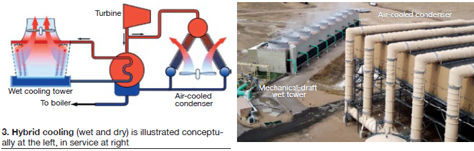
Howell then explained the system in detail, including the complete steam cycle and condensate/cooling system. The example given uses a two-cell wet system to supplement the ACC at a combined-cycle plant in Mexico.
A second retrofit example described adding a third street of cells to an existing ACC at a nominal 80-MW coal-fired facility in Wyoming. After this third street with five larger fans was added, at 97 F ambient, the plant measured 7 MW of additional output. However, power production decreased in cold weather (less than 32F) due in part to more conservative unit operation.
Howell then addressed fan and motor upgrades, which would also be highlighted during the meeting. If there is no water source to even consider hybrid cooling, another option is to increase air flow through the fan system.
In this example, motors were increased from 100 to 200 hp which also meant replacing electrical switchgear, cabling, motors, gearboxes and fans, while completing detailed structural analyses for load-bearing and resonance issues. For this 100-MW plant, 15 new motors, gearboxes and fans were selected, leading to these results:
- Improved ACC performance under adverse ambient conditions.
- No additional water required.
- Increasing the number of blades to nine from four minimized vibration and resonance issues.
- Air flow increased from 542 m3/s to 730, static pressure from 71 Pa to 125.
- Parasitic load increased from 1.12 to 2.24 MW because of the larger fan drive system.
Significant performance results included:
- Removal of backpressure limitation (sustained improvement at 3.5 in. Hg abs).
- Increase in power output (could increase condenser load; steam flow through the turbine).
- Improvement in heat rate (lower condenser pressure/backpressure on the steamer—so-called “free power”).
Howell then highlighted the presentation conclusions:
- 1. ACC performance is critical to low-cost unit operation.
- 2. Initial ACC design is critical to achieving suitable unit-specific baseline performance.
- 3. Careful and consistent operating practices can optimize unit performance.
- 4. Retrofit options can improve performance and reduce plant operating costs.
Ensuing discussions covered ACC permitting, design temperature selection, wind speed as a factor in thermal design, and a conclusion that retrofit projects tend to offer immediate results.
Gearbox maintenance
David Rettke, maintenance specialist, NV Energy, expanded his assigned topic of gearbox maintenance to include, and stress, condition-based maintenance (CBM). His talk was filled with examples of how CBM, if applied correctly, also allows fine tuning for long-term plans, improving long-term performance and value. Rettke highlighted, and exemplified, continuous active involvement in plant operations and maintenance.
At the Walter M Higgins Generating Station, Rettke is intimately involved in ACC maintenance. He champions the plant’s programs for continuous performance improvement, root cause analysis (RCA), vibration monitoring, and CBM.
The effective CBM meeting, he noted, should have a 10-item agenda:
-
- 1. Maintenance history.
- 2. Operator interviews and surveys.
- 3. Safety issues.
- 4. Operational issues.
- 5. Maintenance issues.
- 6. Predictive tools data and results.
- 7. Root cause analysis results.
- 8. Possible continuous improvements.
- 9. Action items with dates.
- 10. Individual division of responsibilities.
Specific to ACCs, Rettke offered examples from Higgins. Some of the CBM discoveries were:
- Safer gear reducer change-out using a fixture that bolts directly to the reducer.
- A way to remotely monitor gear reducer and motor vibration and oil pressure.
- A fixture to secure the hub with blades attached during gear-reducer change-outs.
Some direct benefits of CBM at Higgins include:
- All oil changes are determined by oil sampling, prior to filtering.
- Oil changes are based on sampling, not hours.
- Gear-reducer lube is filtered biannually.
- Blade angle and condition are checked annually and precisely recorded.
- Weekly walkdowns are performed for the entire ACC system by mechanical staff and include equipment and structure inspections.
Rettke stressed that these walkdowns (144 steps up and 144 steps down) – “have caught many significant issues over time.” He followed with specific examples, including:
- Loose turnbuckles.
- Sealing media falling out of position between tube bundles and cell walls.
- Door hinges failing.
- Lights not working.
- Structure bolting missing or loose.
- Decking and grating not properly fastened.
- Various weld repair requirements.
- Repair needs for expansion joints from steam turbine to ACC.
He then declared, “An ACC is a live structure. It moves. Things come undone.” This statement reinforced the value of consistent and comprehensive observation.
Rettke followed with a review of specific procedures and tools developed at Higgins, ending with a review of root cause analysis. He is both RCA administrator and RCA participant, and noted “Sometimes you need to do an RCA on the RCA.” He then added: “Please remember that RCAs also have value when you do something right!”
Rettke clearly captured the post-lunch participants—a difficult assignment. Lengthy discussion followed on inspection and maintenance methods, experiences, and specific safety issues and techniques.
Tube-bundle cleaning
The term tube-bundle “fouling” had been used earlier in the day, and Huub Hubregtse, ACC Team Technology, offered specific examples and cleaning methods.
“Fouling,” he explained, “consists of fibers, dust, pollen, and other materials on ACC bundles restricting air flow, reducing heat transfer, and increasing backpressure at the turbine exhaust.” Such fouling normally has a fairly weak bond (Fig 4) and often can be removed by spraying high-pressure water.
Scaling is more difficult. A layer can be deposited on the fins by fumes, spraying water with high dissolved solids on the bundles, or gearbox oil leakage. This layer cannot be removed by water spray alone (Fig 5).
Some types of scale foulants have a strong bond from limestone deposits, oil contamination, or chemical fumes mixed with the cooling air. This must be dissolved in water or with chemicals.
After the use of chemicals, solvents and/or blasting with sodium bicarbonate, the residual deposit must be removed by high-pressure cleaning. If residue remains, it can become baked onto the finned tubes, forming a hard layer.
Cleaning is normally required when the internal static pressure rises to a certain level because of restrictions in the spaces between fins, normally detected by high condenser backpressure. Levels are site-specific.
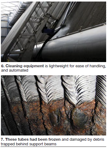
For normal fouling, most cleaning equipment is lightweight and easy to handle, as with the washing system shown in Fig 6. Hubregtse concluded with examples of automatic cleaning systems, noting that most of the setup costs are in the rails. These systems, he said, are relatively simple and moderately priced. Automation, setup time, and cost discussions followed.
Willis Shook, Conoco Systems, continued with three detailed case studies on water-wash tube cleaning, emphasizing that it is not unusual for an ACC project to encounter the unexpected.
The Yellowstone Power Plant ACC experienced severely leaking tubes. Ambient temperatures covered an extremely wide range, and local industries contributed to fouling.
The 65-MW facility is equipped with two pet-coke-fired fluidized-bed boilers, one steamer, and one ACC. The last has 10 modules consisting of eight condensing cells and two reflux cells. Each module contains one fan and six finned-tube bundles. Each bundle has 211 coated carbon steel oval tubes in a three-tube arrangement.
Fans are 26 ft in diameter, have 10 blades, and two-speed motor drivers that can be reversed in severe weather.
Some tubes had been frozen and damaged by debris trapped behind support beams, as shown in Fig 7.
Holes had also developed in the top of the tube connections to the steam header, and at the lower condensate header connections (reflux cells)—caused by corrosion from washing with poor quality water.
Yellowstone solutions included the following:
- Use of underground cable shrink wrap and aluminum duct tape to patch major leaks in tubes.
- Use of sleeve inserts and outer sleeves to fix tube-to-header connection leaks.
- Sandblasting and pressure washing of tubes to remove debris from finned areas.
- Use of epoxy paints to help preserve and close pin-hole leaks in steam header and condensate header connections.
- Wind fence.
- Upper wind wall.
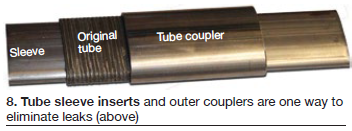
Outer tubes were removed for access to inner-row tube leaks. Tube sleeve inserts and outer couplers (Fig 8) were installed. Condensate holes were repaired and coated with epoxy paint for added protection.
Another example plant burns coker gas from a nearby refinery. Steam is then sent back to the refinery. A harsh winter partially froze the coker gas line, creating a blockage backed by high pressure. When the blockage broke free, pressurized oil leaked through the loop-seal stack. Oil covered the outside surface of the ACC and the surrounding area.
Then another unexpected event. A truck carrying flyash overturned near the plant in winter, and the ash was sucked into the ACC fans. The undersides of the tubes were coated with oil and ash, with the oil acting like a glue.
Attempts to clean using the installed high-pressure water system failed. An adjustable and higher pressure system was brought to the plant. Bundles were presoaked with biodegradable degreaser, then the unit was cleaned with the higher pressure ACC cleaning system.
Air in-leakage testing
Conoco Systems’ Andy Leavitt, followed Shook, covering leak detection equipment and set-up, air in-leakage indicators, and testing challenges specific to ACCs. Standard in-leakage indicators are high backpressure, dissolved oxygen, and continuous hogger use.
His message of caution: The leak is not always in the ACC. It could be in the hogger or hogger exhaust, the gland-seal drain/trap, the crossover bellows, or base weld leaks in retrofit projects. “But even more frightening,” he said, “is finding leaks in new units.”
Discussions followed on the best media. “Helium is the best tracer gas,” he concluded.
This presentation offered large variety of leak locations and detection examples. Day One ended with, in Leavitt’s words: “ACCs present lots of possibilities.”
Day Two
A key feature of ACC User Group annual meetings is interaction.
Barry Dooley led off Day Two by listing and reviewing the long list of questions he had been asked during the Day One breaks, the evening gathering, and breakfast. FAC mechanisms (and color indications) topped the list. Related questions centered on the speed of change (damage), determining iron levels, elevated ammonia levels in summer, optimum makeup, pH balance and maintenance, and clarity of compound turbulence indicators.
An understanding of pH impact seemed critical. Said Dooley, “Two-phase FAC is very sensitive. For example, a system pH of 9.6 can start the FAC process. A pH of 9.8 can stop and reverse it.”
He then offered a brief presentation on aluminum cooling towers and jet condensers (indirect dry cooling). Operations and investigations (industry education) are following a path similar to ACCs (discussed in Day One). This time, however, “IAPWS is working on it up front and is, as one example, monitoring aluminum and iron levels.”IAPWS is currently studying supercritical units with Heller Towers and jet condensers.
“We now know,” Dooley continued, “that for these units we need a pH level of 8 or lower under oxidized conditions, so this is the opposite of ACCs. And we have to realize that the corrosion products (for monitoring) are soluble, not particulate.”
Ongoing work will be discussed at future meetings of the group.
Film-forming agents
Paul Hattingh, Anodamine Inc, followed with the topic “Application of a film-forming agent and corrosion reduction in ACCs.” Subtopic was non-toxic, OEM-compliant metal protection: A surface-active metal passivation technology for low-, medium-, and high-pressure boilers.”
Visuals then clarified the process stages:
- Stage 1. Anodamine permeation through oxide to virgin base metal.
- Stage 2. Partial epitactic hydrophobicity; base metal protection.
- Stage 3. Complete oxide hydrophobicity. Protection achieved with continuous 1000 to 1500 ppb equilibrium residual. Dosage then can be reduced to maintain 800 to 1000 ppb.
Anodamine was contrasted with conventional film-forming amines (FFAs). Although research continues, some FFAs show various limitations—including trapping of inorganic contaminants and base-metal attack through under-deposit corrosion.
Specifics for Anodamine included reduced corrosion-products transport during cyclic operation, improved unit startups, and reduced operating costs. Case studies and economic examples were presented.
Discussion questions included relationships to FAC mechanisms (ongoing study), collaboration with IAPWS, and a statement of no known impact on system pH control.
Windscreen analysis
Reinforcing ongoing studies on the impact of winds, Cosimo Bianchini, Ergon Research, presented “Windscreen protection design based on CFD analysis.”
As reported in CCJ 2Q/2016, p 60, wind impacts both the ACC and plant performance (power output) through degraded fan performance and recirculation of hot air into the downwind fan inlets. This presentation estimated a nominal 10% power reduction for every 10 m/s (22 mph) of wind.
Also, as reported previously in this periodical, the economic breakeven point remains uncertain for windscreen design and installation. Some gains are difficult to estimate, but performance improvements are being reported and analyzed.
Bianchini’s presentation gave details on the 3D computational method; sub-models for fans, tube bundles, and screens; and expected outputs.
Case studies followed for comparison of various windscreen designs and configurations. Key elements are screen porosity and positioning. Also significant are any surrounding tanks, buildings, and geographic characteristics.
Conclusions drawn by Bianchini were that “3D CFD modeling of plant layout and components provides a reasonable and detailed estimate of the wind field around the ACC. It is now possible to verify several windscreen configurations to determine the most effective solution.”
Direct-drive motors
At the 2014 ACC Users Group meeting in San Diego, Tom Weinandy, Baldor Electric/ABB, presented “Design Considerations for a direct-drive motor retrofit on an ACC.” He returned in 2016 with updates, discussing the prototype installations at Basin Electric Power Co-op’s Dry Fork Station in Gillette, Wyo.
The basis of this multi-year work is an agreement between Baldor and Basin to supply two direct-drive ACC motors for an 18-month evaluation period (April installations 2015 and 2016).
Dry Fork is a nominal 400-MW coal-fired unit that came online in November 2011. The design includes a 45-cell ACC. Initial operations showed some significant issues:
- Motor bearing failures attributed to shaft-down orientation.
- System operations during peak season required 15% to 20% more air than could be provided with existing motors.
- Half of the gearboxes were leaking oil.
- Local wind gusts of up to 80 mph caused equipment concerns.
Dry Fork wanted a 250-hp (at 104 rpm) direct-drive design with a carrier bearing for added protection against side loading.
Weinandy began with a quick review of direct-drive technology, introduced to the cooling- tower market in 2008 with shaft-up configuration. Baldor launched its shaft-down, direct-drive ACC design in 2013, based in part on discussions at the 2012 ACC Users Group meeting in Gillette.
Considerations included more horsepower and torque, less noise, and a robust mechanical strategy to address wind issues. Weinandy provided full details, including the drive motor controls.
Retrofit installation challenges discussed included a drive-motor weight of 7679 lb but an existing trolley system rated below 5000 lb, and an increase in motor size.
Based on successful installation and operation of these prototypes to date, Weinandy stated that “it is their intention to replace the balance of the fan units with direct-drive technology.” Timing is not yet determined.
OEM ACC specifications
Many questions about OEM specifications were raised and discussed at the 2015 meeting in Gettysburg, and Gary Pratt, engineering manager at Advisian/WorleyParsons, brought both pinpoint suggestions and good common sense rules to Dallas.
Pratt began with the basics: Prepare a specification that leads to an ACC that meets all codes, achieves optimal thermal performance, meets all permitting and environmental restrictions, epitomizes quality throughout, and is easy to maintain. And all at the right price—of course. He called it a balance of “infinite wants within a finite budget and schedule.”
“Homework is absolutely critical,” said Pratt, and we can’t forget two sometimes overlooked but critical details:
- 1. Cycle chemistry must be part of the homework, how the ACC fits into the cycle as a whole, and. . .
- 2. You must consider ACC requirements for the current (and foreseen) generation of flexible and fast-start combined-cycle plants.
Pratt’s credibility? He is a seasoned design engineer who communicates directly and frequently with plant owner/operators and site personnel.
Pratt quickly drew a distinction between ACCs and surface condensers. First, ACCs are more complex, with more technical scope. Second, there is less history with ACCs, and industry standards have not fully caught up with the operating experience. As an example, surface condenser standards from the Heat Exchanger Institute are in their eleventh edition. HEI standards for ACCs are in their first.
Therefore, when drawing up a specification, more responsibility is placed on both the engineer and the end user to properly specify and establish all relevant design criteria. At its highest level, the ACC specification must also cover requirements for the overall project.
Expanding, he listed the common sources of specification input:
- Design engineer knowledge and experience.
- Operating experience.
- Industry standards.
- User-group interaction and reports.
- Industry subject matter experts.
- Equipment manufacturers and suppliers.
- Construction and commissioning lessons learned.
He carefully reinforced the requirements of listing precise project communication and coordination methods, a rigid division of responsibilities, a fully loaded schedule, and logistics including inspection points, quality assurance, field testing, and guarantees.
He added specifics on terminal points, submittal schedules, drawing quality standards, approval cycles, and records retention.
On the product (OEM) side, Pratt also emphasized two general categories of requirements: Those that meet established codes and standards (building code, for example), and those more difficult to define: What the owner/operator is thinking about for best value, and the technology target that moves as user experience expands (perhaps during the contract period).
On the overall project side, Pratt pointed out several key elements—including full meteorological and topographical site data, and wind data for all seasons. Equipment location should be based on numerous factors—including wind, adjacent structures, space and height limits, and noise.
He ended with a list of current (and perhaps more difficult) topics, concerns, and ongoing developments, including:
- Motor selection: single speed, dual speed, and VFD.
- Windscreens.
- Fan and bridge vibration.
- Tube and fin materials (and cladded versus coated).
- Fans and gearboxes.
And for base awareness, he stressed two important items:
- 1. “Achieve clarity. If it’s not written down you’re not going to get it.”
- 2. “Stay connected with the industry. Lessons learned prevent repetition of errors.”
During comments and questions, Dooley suggested including IAPWS information with similar items (ASME Performance Test Codes). Interesting discussions followed on codes and other requirements that can vary by state.
Gear standard update
The Cooling Technology Institute outlined its proposed ACC gearbox standard, and requested input. CTI intends to complete a new standard that will offer reliability and minimal maintenance through:
- Robust product design specifically for ACCs.
- Proper sizing and selection.
- Proper installation.
- Best practices in operation and maintenance.
Initial meetings were held at the CTI Summer Workshop in July 2016. Attendees included three gear manufacturers, several ACC designers, EPC firms, fan manufacturers, but only one owner/operator.
Key issues addressed included gear ratings and service factors, wind effects on design, oil containment and filtration, and condition monitoring.
The update ended with an appeal for input from owner/operators. The committee chair is Craig Burriss of Amarillo Gear Co. Anticipated publication is in the first half of 2017.
Fogging enhances dry cooling
Huub Hubregtse returned to the podium and presented a case study on spray-enhanced cooling to help ACC performance during high ambient temperatures.
Some methods include wetting the heat-transfer surface (more common in Europe) but this can also cause corrosion of the tube bundles, damage to motors and gearboxes, algae on the structure and equipment, and limestone fouling when using hard water.
Fogging is often preferred. A fogging mist is released into the air flowing through the fans and tube bundles. The mist evaporates quickly, cooling the air. The only requirement is a relative humidity of around 50% to 60% (allowing evaporation to take place). The maximum quantity of water used is that needed to achieve 95% to 100% relative humidity.
Hubregtse presented a practical example using a four-cell ACC, ambient temperature of 86F, and relative humidity of 50%, referencing the Mollier diagram. Results included a boost of 2.21 MWh per day.
Also for this example, evaporation required water droplets of between 25 and 40 microns, calling for either an atomizing or a high-pressure spray nozzle system. The latter, with its large number of nozzles, is considered the most efficient.
He then reviewed, in detail, specifics on nozzles, sensors and controls, and water quality. Soft water must be used.
Hubregtse also stressed the impact on the gas turbine. “If the backpressure at the turbine exhaust reaches the trip point during high ambient temperatures, fogging can lower the vacuum enough to prevent this.”
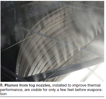
In the discussions, Hubregtse confirmed that evaporation takes place before entry through the tube bundles (Fig 9), so there is no fouling impact.
External inspection guide
In 2015, the ACC Users Group published the first draft of an internal ACC inspection guide (ACC.01), currently available at www.acc-usersgroup.org/reports. Dave Rettke brought 2016 participants up to date on the document.
His presentation discussed the guide’s organization and depth. If this goes “too far down into the weeds,” said Rettke, “to valves, for example, that is going too far. Valves vary by plant, and they have their own manuals. The best foundation is perhaps any external inspections discussed in OEM manuals.”
Areas of initial concentration are decking, steam ducting, and expansion joints. Other headings being considered are piping and hangers, tubesheets, tube washing systems, structural members, fans and motors.
The goal of ACC.01 is to improve both safety and performance. Photos and a checklist will be included in the final document. A progress report will be presented at the 2017 meeting.
Windscreens at Caithness
The windscreens at Caithness have been reported in CCJ, most recently in the 2Q/2017 Outage Handbook issue.
Gary Mirsky, Galebreaker Industrial, reviewed the overall project and offered detailed literature references on this long-term program. “There was never a specific performance problem,” he explained. “It was amperage, fans, vibrations, and motor-trip problems, all causing concerns.” Motorized screens were installed, and the fans were changed from six blades to nine.
The conclusions to date, said Mirsky, are the following with the screens normally at 50% deployment:
- 1. Differences in back versus front cell air velocities are normalized.
- 2. Dynamic blade loading is reduced considerably.
- 3. Longer fan blade life is projected.
- 4. Measured static pressure differences are reduced.
- 5. Average static pressure is reduced indicating air flow increases.
The update gave an interesting perspective on what is both an expanding and analysis-driven technology.
Dry cooling research
A research summary presentation by Addison Stark, program director, Advanced Research Project Agency—Energy (ARPA-E) explained the goals of this US government initiative to help improve efficiency, reduce energy imports, and reduce energy-related emissions. Efficiency related to decreasing water availability was the topic in Dallas.
Three overriding facts were presented to support the theme of “Energy as a water problem”:
- 1. 41% of freshwater drawn in the US is for thermoelectric power plant cooling.
- 2. 3% of cooling-tower water load is evaporated and dissipated.
- 3. Energy and agriculture are competing for the same fresh water resource.
Referencing studies that included EPRI and DOE, Stark gave these statistics for the US powerplant infrastructure (2008):
- Water cooling, 99% (cooling tower 42%, once through 43%, cooling pond 14%)
- Dry cooling, 1%. Direct air-cooled condenser dominates. Indirect dry cooling and hybrid cooling are minimal.
Stark also stated that “More stringent EPA regulations on water intake and thermal discharge will render once-through cooling obsolete” in the future.
He then addressed air versus water cooling and introduced the Advanced Research in Dry Cooling (ARID) program launched in 2015, with 14 projects, including air-cooled heat exchangers. Project teams design kilowatt-scale testing prototypes to ensure the technologies can scale up to the megawatt-cooling capacities of real systems without significant performance loss.
Discussion points included a reminder from ACC owner/operators that good theoretical developments can cause real problems and require some degree of caution.
Midlothian Power
Terry Hiefner, engineering supervisor, Midlothian Energy Facility, Engie NA, followed with an overview of the plant the attendees would tour the next morning, and its activities. Midlothian, located just south of Dallas/Ft Worth, consists of six single-shaft, F-class combined cycles, the first of which began commercial operation in 2001. Total rated output: 1495 MW.
Hiefner concentrated on the ACCs—including maintenance activities, instrumentation, windscreens, a multi-year and multi-unit fogging project, and near-term plans for direct drives and fan conversions.
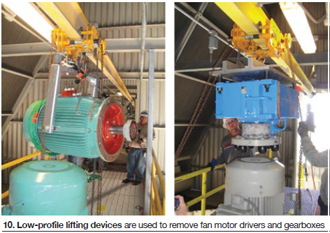
He began with the motor/gearbox/bearing assembly details, describing maintenance activities as:
- Component rigging improvements.
- Trolley-beam south wall extensions.
- Motor and gearbox low profile lifting devices (Fig 10).
- Grating rigging access for fan inlet screen.
- Equipment failure history.
- Preventive maintenance summary.
Reviewing maintenance, he noted issues with the motors and gearboxes, caused largely by water ingress.
Staying with maintenance (and preventive maintenance) Hiefner highlighted schedule details. One significant item was a walkdown each (and every) shift.
Instrumentation specifics include retrofit gearbox oil-pressure transmitters tied to plant DCS (for improved monitoring), and fan cell temperature RTDs to trend fogging performance and monitor any fan stalls attributed to wind velocity or direction.
Windscreens have improved unit performance (output) and are removable for maintenance access and outage laydown. Ground-level screens (Fig 11) were placed based on CFD modeling.
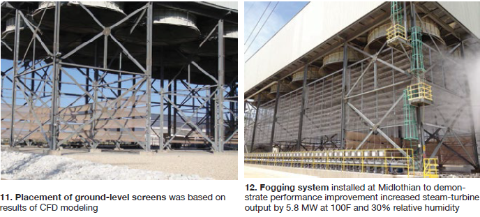
Midlothian’s multi-year fogging project began in 2012 when a 12-stage system, rated 600 gpm of demineralized water at 1500 psig, was installed on Unit 6 as a proof of concept (Fig 12). The 12 levels, located below the ACC, contain nearly 18,000 nozzles in sum (1200 per fan). Variable results average a unit increase of 5.8 MW at 100F and 30% RH (ambient).
Systems were installed on Units 3 and 5 in 2013, with similar performance results.
Midlothian next investigated the placement of nozzles immediately below and above the fans, and in 2014 converted Unit 5 to a mixed system, relocating half of the nozzles immediately below the fans and a separate lower-pressure arrangement (500 psig) above the fans.
Expectations were a 6-MW boost in output, 3 MW from fogging below the fan, 3 MW from fogging above the fan. Actual results with nozzles below and above the fan in operation: 4.5 MW below and 1.5 MW above. The hybrid system improved unit performance at 100F and provided “significant cooling” of 20 deg F.
In 2015, the below-fan nozzle design was implemented on all remaining units. The overall fogging program now includes 90 ACC fans, 180 pumps, and 67,500 nozzles (750 per fan).
The next significant ACC program at Midlothian will be a direct-drive/Hudson fan conversion by Industrial Cooling Solutions (ICS). Attend the 2017 meeting for a progress report.
Meeting participants visited the plant the next morning. As recapped by Andrew Howell, “Plant Manager Mike Knisley and his team went all-out to describe and show their ACCs, including operation of the spray-misting system, for our observation.” CCJ
SIDEBAR: How IAPWS helps ACC owner/operators
Technical guidance documents (TGDs) have been developed by the International Association for the Properties of Water and Steam to provide advice on cycle chemistry to users responsible for fossil and combined-cycle plants. The documents, available at no cost on the organization’s website at www.iapws.org, represent the accumulated experience of members of the IAPWS working group on power cycle chemistry from 24 countries.
- Monitoring and analyzing total iron in fossil and combined cycle plants (May 2014). Document details represent the consensus of 24 countries.
- Film-forming products (September 2016) received final review and approval from the two-dozen countries represented in IAPWS. Reviews included most of the chemical supply companies and most of the steam turbine, boiler, and HRSG manufacturers.
- Procedures for the measurement of carryover of boiler water and steam (September 2008) includes a technique for measuring carryover from drum boilers to assist in preventing steam turbine failure/damage.
- Instrumentation for monitoring and control of cycle chemistry for the steam/water circuits of fossil-fired and combined-cycle powerplants (September 2015) includes a table that can be used to determine the minimum level of instrumentation required for any fossil or combined-cycle/HRSG plant.
- Volatile treatments for the steam/water circuits of fossil and combined-cycle/HRSG powerplants (July 2015) includes the basis for AVT and OT for all plants, with customization for plants with ACC and using ammonia and amines. Recently added guidance is offered for fast start and frequently started HRSGs.
- Phosphate and NaOH treatments for the steam/water circuits of fossil and combined- cycle/HRSG powerplants (October 2015) covers the basis for selecting the optimum boiler/HRSG evaporator water treatment (phosphate and NaOH) for all drum plants, including customization for plants with ACC.
- Steam purity for turbine operations (September 2013) offers guidance for a wide range of turbines (fossil, nuclear, industrial, geothermal, etc) and failure mechanisms. It includes customizations for plants using amines.
- Corrosion product sampling and analysis (May 2014) covers the optimum procedures and techniques for monitoring iron and copper. A table of achievable iron levels for plants with ACCs is included.
- HRSG HP evaporator sampling for internal deposit identification (September 2016) includes the locations where to take samples from HRSGs, how to analyze the samples, and a new IAPWS map to assist in determining whether the HRSG HP evaporator requires chemical cleaning.
- Application of film-forming amines in fossil, combined-cycle, and biomass plants (September 2016) covers optimum application guidance for FFA/FFA products in all-ferrous plants. It includes customizations for shutdown/layup, multiple pressures, mixed-metallurgy feedwater systems, condensate polishing, and air cooling.