


‘Interactive Plant’ tracks PMs, calibrations, documentation, important dates
Best Practices Award
 Corona Cogen’s Interactive Plant Management System (Interactive Plant), developed primarily by I&C Tech Todd Woodworth, has been in service for over a year. The program uses current operating data and baseline information to track required calibrations, plus PMs for instrumentation and electrical systems.
In simple terms, Interactive Plant provides the tools to monitor compliance, maximize efficiency, and provide easy access to information, thereby minimizing operating costs, facilitating maintenance, maximizing availability/reliability, and raising compliance awareness.
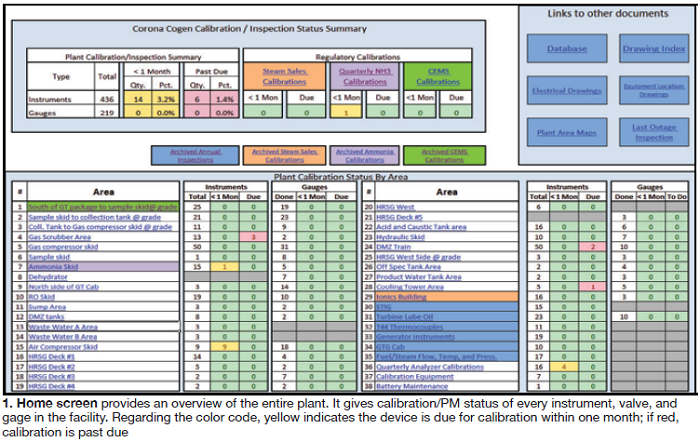
Interactive Plant relies on Excel files to link maps, drawings, and calibration information into an intuitively indexed format. When used properly, it assures regulatory compliance. The home screen is the starting point: It offers an overview of the entire plant, providing the calibration/PM status of every instrument, valve, and gage in the facility. Note that the individual cells are color-coded to indicate the status of each device. Specifically, if the field is yellow, calibration is required within one month; a red field means the device is past due for calibration.
The Plant Calibration portion of the status summary box at the top of the Home Screen (Fig 1), shows the percentage of devices that either are out of calibration, or pending, plant-wide. The Regulatory Calibrations field indicates the status of each type of required calibration and has links to more detailed information. Immediately below that are links to archived calibrations.
The “Links to other documents” block in the Home Screen allows users to access the following:
- Electrical Drawings links to electrical and instrumentation schematics.
- Plant Area Maps contains construction drawings.
- Drawing Index links to location drawings.
- Database connects to a listing of all instruments and their specifications.
- Last Outage Inspection opens the latest outage report with all applicable calibration and maintenance information.
- Equipment Location Drawings divide the plant into sections and provide instrument and valve locations.
The lower portion of the Home Screen contains the Plant Calibration Status by Area field. It provides the status of that area as well as a link to a more detailed breakdown of the devices in it. Clicking on a link under the Area column opens the summary of that area. The links at the upper right will return you to the Home Screen or to a drawing of the area with instrument locations.
The Gauges section tracks the last time gages in that area were checked, while the Instruments section lists every valve and device in the area and the last time it was calibrated, its calibration frequency, and calibration due date. The column on the right will be green if calibration is complete, yellow if calibration is due within one month, and red if overdue.
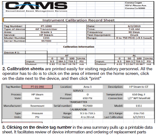
Clicking on the Date Done link opens a printable Instrument Calibration Record sheet for the device on that date (Fig 2). Clicking on the device tag number brings up a printable data sheet, which can be used for ordering replacement parts (Fig 3). Printing a calibration record for a visiting regulatory agency is simple: Click on the Area from the Home Screen, then click on the date listed next to the device and print.
A secondary feature of Interactive Plant is drawing and map indexing. The Drawing Index has links to maps, location drawings, schematics, construction drawings, system summaries, and manuals. Quick retrieval of needed information is the primary advantage of this feature. The Drawing Index Map (Fig 4) is a scaled plant map that acts as the drawings index. Each junction box, building, or piece of equipment highlighted in green is linked to another drawing. Any drawing can be retrieved in from two to four clicks.
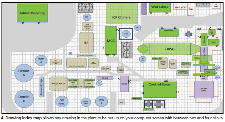
Example: Clicking on Control Room opens a detailed scaled map of that space which also has green fields linked to drawings for various junction boxes and equipment. For the HMI, a complete set of PLC termination drawings and manuals can be accessed. Related documentation, such as construction drawings, can be retrieved from a list provided on the control room map.