


Water mist replaces obsolete fire protection system

This 536-MW, gas-fired, 2 × 1 combined-cycle cogeneration plant, powered by 501FD3/6 gas turbines, is located in Klamath Falls, Ore
Plant manager: Dennis Winn
Solution. The size of the turbine enclosure encouraged replacement with the Victaulic Vortex Hybrid Water Mist Suppression System (Figs 1 and 2). Features: Water droplets smaller than 10 microns (100 times smaller than water particles from traditional water- mist systems) and nitrogen are discharged from nozzles located throughout the enclosure.
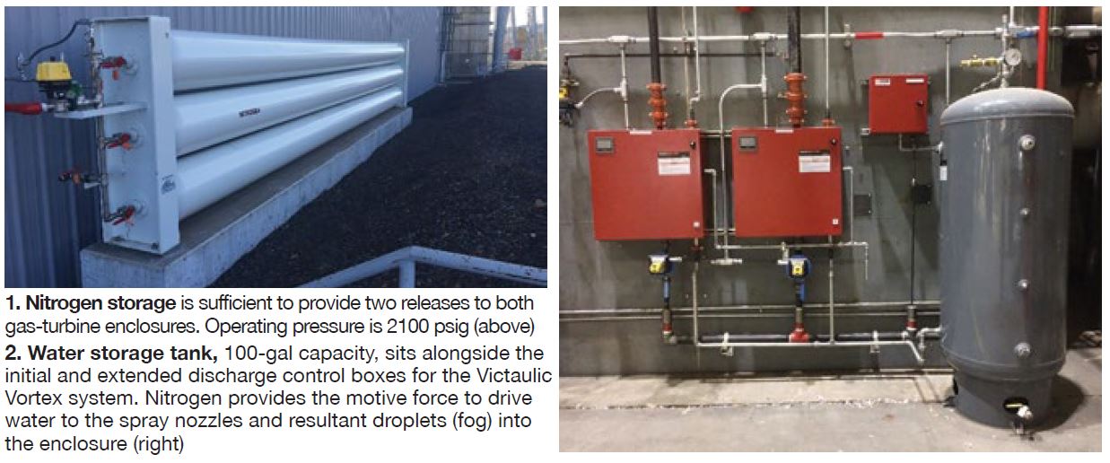
This system provides for nearly zero wetting, no costly cleanup or equipment replacement, quick recharge, no need for assurance of tight room integrity, and, finally, a green design safe for people and the environment.
Suppression capabilities are improved by providing significant thermal cooling as well as a prolonged period of inert atmosphere while the turbine spools down and temperatures fall below the autoignition temperatures for oil and natural gas. Importantly, the fire-suppression atmosphere created is capable of sustaining life while activated.
Alternative solutions for the electrical and mechanical packages are described in Figs 3 and 4.
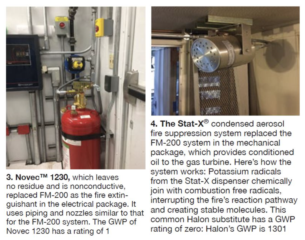
Results. Installing the systems described allowed the site to remove the existing FM-200 systems that are less safe and contribute more substantially to global warming. FM-200 has a Global Warming Potential (GWP) of 3220, considerably higher than that of the Victaulic Vortex™, which incorporates nitrogen and water-mist extinguishing agents.
Project participants: Scott Nelson, Mark Mayers, Greg Dolezal, Dennis Winn, Chris Volk, Bruce Willard, Alan Scales, Joy Corner
Evap-cooler improvements save water, extend media life
Challenge. This site’s gas-turbine air inlets are mounted on the roof of the generation building, which totally encloses both engines; inlets are located 50 ft above ground level. The air intakes are horizontal and equipped with a self-cleaning pulse-type filtration system plus evaporative cooling.
In the evap coolers, pumps continually circulate water from a lower reservoir to the top of each module and evenly distribute it over the media. A percentage of the circulating water is blown down continually to reduce the concentration of minerals and other waterborne contaminates that over time would leave deposits on the media. Water lost to evaporation and blowdown is replaced with service (potable) water.
Personnel regularly checked the evap coolers to verify their proper operation—specifically, that basins were not overflowing or at levels so low as to cause circulating pumps to trip.
Frequent adjustments to, and maintenance of, the floats in the level-control systems were required.
A goal of the operations team was to reduce the number of times personnel had to visit the evap coolers on rounds.
The solution was to add solenoid valves for filling and draining the basins (Fig 5) and level detectors that could be monitored remotely in the control room (Fig 6). Both features were incorporated into the Siemens T3000 DCS. Advantages of automating the evap coolers are the following:
- Fewer visits by O&M personnel to the roof to adjust/fix the fill valve and float.
- Reduced cycling of the circulating pumps when low water levels in the basins would activate the cutout switches.
- Known basin levels that could be trended.
- Automated filling when ambient temperatures and baseload operation require evaporative cooling.
- Each fill valve received independent commands for filling and draining, allowing a water system already at its limits to be more capable of filling the basins.
- Automated draining of the basins during cold weather to prevent nighttime freezing.
- Ability to dump and fill the water basins from the control room when high conductivity so dictates.
- Tighter control of basin levels is possible. The old float was located near the man-door of the basin and the incoming air flow would cause turbulence in the float area. The new level indicator was relocated to the pump suction bay and placed in a stilling chamber, allowing much tighter control tolerances.
![]()
Results. Feedback from the operators has been positive. The media has had less calcium/magnesium buildup than in previous summers because of the ability to dump and refresh the basins’ cycled-up fluids. This is predicted to add approximately three years to the life of the media.
Additionally, potable-water loss has been virtually eliminated. Reason: The basin no longer overflows. Gas-turbine performance also has improved because the evap coolers are more reliable. The total financial impact of the improvements will be monitored over the next couple of summers to evaluate project effectiveness. Stay tuned to CCJ for updates.
Project participants: Scott Nelson, Mark Mayers, Doug Hudson, Spencer Greer, Bruce Willard, Dennis Winn
Cooling-tower cell platforms reduce cost, promote personnel safety
Challenge. Klamath’s counterflow mechanical-draft cooling tower is equipped with 200-hp, two-speed motors in each of its eight cells. Their one-piece, fully floating, composite horizontal drive shafts transmit motor torque to the right-angle gearboxes connected to each fan. Because no permanent work platforms were installed in each cell, maintenance was time-consuming and personnel safety was called into question.
Solution. Quotes for permanent work platforms were requested from several companies. The alternative, temporary platforms, was expensive. Each time personnel entered a cell it cost about $5000 in materials and labor to erect and remove scaffolding. Plus, there were performance impacts. For example, a loss of 0.4 in. Hg in condenser backpressure was experienced during a single-cell lockout, which typically lasted four hours. This amount of backpressure loss equates to a 0.8% decrease in plant output and 0.8% increase in heat rate.
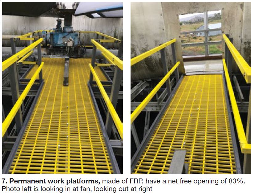
The platform design selected covers 152 ft² and its FRP panels have a net free opening of 83% (Fig 7). This means the panels reduce the airflow area in the 30-ft-diam cells from 707 ft² to 681 ft². The 83% of net free opening was considered essential to avoid a disruption of air flow.
During this same outage, the plant installed new blades and bolting hardware on the fans. To minimize the effect of the air-flow restriction, the amperage of each fan motor was checked before the outage began. The average horsepower was calculated to be 183. The angle of each new blade was adjusted to maximize the horsepower output to 200. Re-blading required a re- torqueing of the new hardware after 50 hours of fan operation. Thus, the new platforms started their return-on-investment shortly after re-start with a saving of $40,000.
Finally, the site purchased new cooling-tower fill and drift eliminators. The original fill had 1- in. openings because designers feared the use of secondary effluent from a nearby treatment facility would foul the fill. Years of operation showed this did not occur and the new fill has openings of 0.75 in., allowing for more contact surface area with no effect on air flow.
Results. All of the above items help to reduce the impact of the new safety platforms. Now personnel can access gearbox heaters, vibration probes, and perform alignments without have to engage a scaffolding company and crew.
Project participants: Greg Dolezal, Doug Hudson, spencer Greer, Dennis Winn