


Mitigate failures with tighter control of water chemistry, better materials
By Kevin J Boudreaux, Nalco Power
 Rotor air coolers (RACs) are installed in most 501F- and G-class combined cycles to reduce the temperature of compressor discharge air used for rotor cooling. They can be air-to-air heat exchangers (fin-fan coolers) or water can be used as the cooling medium (Fig 1). Siemens Energy Inc often refers to its air-to-water exchangers as kettle boilers; Mitsubishi Power Systems Americas Inc calls them TCA (turbine cooling-air) coolers.
Air-to-water exchangers are built to Section 8 of the ASME Boiler and Pressure Vessel Code. Their advantage over fin-fan coolers is that heat is captured by the system, not rejected to atmosphere. Result is a small improvement in plant performance.
All 24 engines in the Siemens 501G fleet rely on kettle boilers for rotor air cooling. Three of these RACs have experienced failures in the low-pressure (LP) section, nine in the intermediate-pressure (IP) section (Sidebar 1). One 2 x 1 combined cycle in the Southwest reported failures in the IP sections of both RACs. Data indicate that all IP RAC failures have occurred between the tube and tubesheet at the seal weld. More importantly, the failures have occurred on the tubesheet and on the weld material, not the tubes themselves.
Industry consensus is that the root cause of the failures is chloride stress corrosion cracking (SCC), based on metallurgical failure analyses. The failures have led to costly downtime and repairs and have generated much discussion at industry meetings regarding corrective action. The OEM’s initial response to the failures was a suggestion to adjust RAC operating chemistry.
This article is a compilation of Siemens G-fleet experience with the goal of helping owner/operators to:
- Better understand the chloride SCC mechanism.
- Determine if there are other extraneous factors propagating SCC.
- Review OEM chemistry recommendations.
- Identify other possible corrective actions for mitigating RAC failures.
| 1. How air-to-water RACs are designed and work
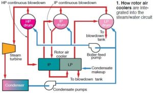
The rotor air cooler (RAC) integrated into combined-cycle systems powered by Siemens 501G engines is a single-pass, shell-and-tube, air-to-water heat exchanger—often referred to as a kettle boiler. It reduces the temperature of a portion of the compressor air flow to cool the rotor, blades, and vanes in the gas turbine. Water is on the shell side of the RAC, compressed air flows through the tubes. The heat exchanger has an intermediate-pressure (IP) section (blue arrow in Fig A) and a low-pressure (LP) section (red arrow). IP water cascades to the LP section as shown in text Fig 1. Tubes and tubesheets typically are made of Type-304 stainless steel. The tubes are rolled into the tubesheets and welded to create a tight seal between the rotor air and the cooling water. Fig B shows the single-pass flow path for the compressed-air circuit. As shown in text Fig 1, blowdown lines from the HRSG’s HP and IP steam drums are integrated into the RAC circuitry. Steam produced by flashing is returned to the IP and LP drums. Condensate is added to the LP RAC, as necessary, to control its water level. Note that blowdown from the LP RAC is the final blowdown for the HRSG; therefore, level and blowdown control of the drums and RAC are both critical and challenging, considering the varying boiler-water chemistry requirements throughout the boiler. Because of the HRSG configuration, cycles of concentration are not the plant’s friend when considering chemistry. Any contaminant introduced with the condensate or makeup water concentrates up in the drums and then in the RAC. Given the complexity of the HRSGs associated with 501Gs, as well as the general lack of instrumentation, it is very difficult to determine the amount of HP and IP blowdown flowing to the IP RAC and the contaminant concentrations present in each of those streams. This obviously makes RAC chemistry control extremely challenging. |

Stress corrosion cracking in RACs
According to The Nalco Guide to Cooling Water System Failure Analysis (Ref 1), SCC is defined as failure by cracking under the combined action of corrosion by specific corrodents and stress. Industry experts generally agree the following three elements must be present for SCC to occur: (1) metallurgy susceptible to stress corrosion cracking by the specific corrodent, (2) elevated concentration of the corrodent, and (3) high stresses. The specific corrodent that most commonly causes SCC in Types 304 and 316 stainless steels is a chloride solution.
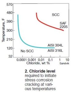 Metallurgies and chloride. Fig 2 shows the chloride levels required to initiate SCC at various temperatures. Also, it illustrates how that potential varies based on specific metallurgies. In regard to SCC susceptibility, Type 304, most commonly used to construct RACs, exhibits the least amount of resistance when compared with other metallurgies appearing in the chart. Note that the chloride concentrations in Fig 2 represent bulk water concentrations and do not take into consideration the importance of concentrating mechanisms such as evaporation and ion concentration cell formation within crevices and beneath occlusive deposits.
Fig 3 shows the difference in bulk-water chloride limits for pitting versus crevice corrosion. As the figure reveals, 100 ppm of chloride in the bulk water may be acceptable to protect against general pitting corrosion at a particular temperature, but that concentration at the same temperature could cause corrosion if a crevice were present. Reason: Contaminants can concentrate within the crevice, and be orders of magnitude higher than in the bulk water. Crevice corrosion is particularly important given the nature of RAC failures.
High stresses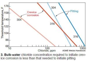 can be applied or residual. Examples of an applied stresses can be tensile, thermal expansion, service loads. Applied stresses can be continuous, intermittent, and/or present only during plant load transients. Residual stress typically is created by cold- working during manufacturing or by welding practices that might benefit from change. Heat treatment can help reduce residual stresses created by welding, but the use of this practice can be limited, according to Ref 1. It is important to note that residual stresses can approach the yield stress. Whatever the stress may be, its presence helps to initiate and propagate SCC when the other necessary elements are present.
Impact of oxygen and high temperature. In addition to the three variables previously identified as necessary to induce SCC, research cited in Ref 1 indicates other elements also must be present—including dissolved oxygen and temperatures above about 140F. The RAC operating temperature, approximately 840F on the air side and more than 450F on the water side, is above the 140F minimum critical temperature, and thus is well within range for SCC to occur.
A DOE report, DOE Fundamentals Handbook: Chemistry: Volumes 1 and 2, adds that as temperatures increase, the time to metal failure from SCC decreases. While operating temperature appears to be a significant and understood factor in RAC failures, it is the influence of dissolved oxygen on SCC that has raised questions. The DOE report also says that when oxygen levels are maintained at low residuals, the potential for SCC is reduced.
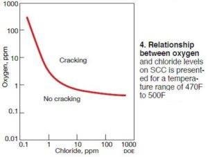
Fig 4, from that report, highlights the relationship between oxygen and chloride levels and their influence on SCC. The temperature range for the data set is 470F-500F, much lower than the RAC’s 840F operating temperature. Recall that as the temperature increases, so does the potential for failure from SCC.
 Because RAC’s are expected to operate with very little oxygen in the bulk water, less than 10 ppb in the feedwater if the HRSG follows EPRI AVT(O) guidelines, one would expect there would not be enough oxygen available to allow SCC to occur under normal operating conditions and under normal RAC chloride levels (Sidebar 3). However, based on reports and analyses, it is clear that the root cause of the failures is SCC. Therefore, it’s important to understand from where, how, and how much oxygen is getting into the RACs.
During commissioning and for the first several years of operation, the 2 x 1 facility cited above for having failed the IP sections in both of its RACs, cycled significantly. This mode of operation caused the plant to break vacuum repeatedly, allowing oxygen ingress when the facility was not in service. This explains how oxygen may have entered the system.
With regard to the amount of oxygen present, saturated water typically contains approximately 8 ppm of dissolved oxygen. The actual amount depends on temperature, but for the purposes of this article, 8 ppm is a good assumption. Fig 4 indicates that, at 8 ppm of oxygen, chloride levels must be well below 1 ppm. With typical bulk-water chloride concentrations of 170 ppb, the concentrations in the crevices easily could be above 1 ppm. Knowing this, it’s easy to understand how SCC can be the root cause for the RAC failures.
2. Ammonia V/L and its impact on RAC pH control
Ammonia’s V/L ratio, the amount of ammonia present in the vapor phase versus that in the liquid phase, varies inversely with pressure—that is, as pressure drops, V/L ratio increases and vice versa. Example: At a steam pressure of 150 psig, V/L is 7; for 2100 psig, it is about 2.5.
This behavior is particularly important regarding pH control in the RAC. Recall from text Fig 1 that HP drum blowdown at approximately 2100 psig and IP drum blowdown at about 470 psig both flow to the IP RAC. As these blowdown streams enter the IP section of the RAC, they flash because of the sudden pressure drop. When flashing occurs, a large portion of the ammonia leaves with the steam because of the change in V/L ratio.
The reduction in bulk-water ammonia concentration depresses the pH. Industry data show IP RAC water can be one pH unit lower than the HP drum water —8.8 versus 9.8, respectively. Considering pH is a logarithmic measurement, this can be significant with respect to corrosion potential. The addition of phosphate, a dissolved alkaline solid that remains in the RAC bulk water, can help increase the pH in any crevices and reduce the potential for stress corrosion cracking.
Failure location on the weld material and the tubesheet is very significant and must be understood. Under ideal conditions, when a tube is rolled into a tubesheet, the seal is sufficiently tight that water cannot migrate between the tube and tubesheet. Therefore, water never should come in contact with the seal weld, which, in turn, would mean no SCC would occur in that region.
However, if a tube is not rolled properly, or if the exchanger sees significant temperature transients causing the tube to contract and expand, a crevice can be created allowing water to migrate between the tube and the tubesheet and contact the seal weld. When this occurs, the water heats up rapidly and boils because of the elevated air-side temperature.
Dissolved solids that were once contained in the bulk water are left behind as steam escapes back through the crevice. This process continues, and the concentrations of impurities, specifically chloride, increase rapidly in the crevice, raising them from ppb levels in the bulk water to probable ppm levels in the crevice.
Based on photos compiled during metallographic analyses, there were definite gaps between the tubes and tubesheets. How the gaps were created remains unclear. Tubes may have contracted and pulled out of the tubesheet when there was a sudden influx of cooler water—at startup or during load transients, for example. Because the tubesheet has more bulk than the thin-walled tubes, the tubes will thermally contract at a faster rate.
Upon a return to normal operation, the tubes may not reseat in the same manner, and gaps/crevices may be produced. If gaps exist between the tube and tubesheet bores, the stress on the weld increases because the tube is not restrained within the bore. While SCC is the root cause of the failures based on metallurgical analyses, it is possible that fatigue helped to accelerate the failures.
3. Chloride levels in HRSGs and RACs
Industry chemistry guidelines generally call for less than 3 ppb chloride in demineralized makeup water and condensate; combined cycles typically report 1-3 ppb during normal operation. For the example that follows, 2 ppb is assumed.
Tracing the HRSG/RAC water flow path in text Fig 1, condensate containing 2 ppb enters the IP/HP boiler-feed pump, which takes suction from the condensate-pump discharge header. In the HP drum, chloride concentrates approximately 50-fold to 100 ppb. This means blowdown with 100 ppb chloride is fed to the IP RAC, where it concentrates another three or four times to a nominal final IP RAC chloride level of 400 ppb.
This simple illustration does not consider that IP-drum blowdown dilutes the concentration of chloride in the IP RAC. Analyses indicate that 200 ppb chloride in the IP RAC is not uncommon, which in itself contributes approximately 2.4 µmho to cation conductivity. Important: This is the bulk-water chloride concentration and does not reflect the concentration mechanism that occurs in crevices during heat transfer. The takeaway here is that it may be very difficult to reduce the bulk-water chloride concentration to a level that assures an acceptable chloride concentration in tube-to-tubesheet crevices.
Studies and metallographic analyses confirm that SCC is causing the failures in the RACs. However, it is possible that the role of oxygen and the mechanical aspects of the RAC construction have been underestimated when it comes to the true root cause of the SCC. It is clear that any crevices created, whether from the manufacturing process or the tubes contracting and expanding during plant load transients, can allow ppb level chloride in the bulk water to concentrate to the ppm level in the crevice. Couple this with added applied stresses—such as temperature and vibration—and the susceptibility of the RAC to failure increases.
Preventing SCC is neither simple nor straightforward. It has been suggested that reducing chloride levels in the cycle chemistry, together with the addition of trisodium phosphate, will help reduce the potential for SCC. While it stands to reason that this is a prudent course of action, the plant’s operating profile and other factors likely would make the desired goals very difficult to achieve. Mitigating SCC may require more than chemistry changes alone.
The path forward
The most effective means for minimizing SCC potential are reducing applied and/or residual stresses and controlling the local environment—that is, preventing to the degree possible, stagnant areas and crevices where contaminants may concentrate. Formulating a path forward to reduce the SCC potential, and thus RAC failures, should have three focal points: chemical, operational, and mechanical. All of these are intertwined.
Some 501G plants have made chemistry adjustments—such as feeding trisodium phosphate directly to the RACs and minimizing chloride levels in the cycle water—based on the OEM’s initial attempt to provide some direction (Table 1). However, high concentrations of the alkaline agent would be needed to neutralize the acidic environment present.

And if the caustic injected were to concentrate to excessive levels, say greater than 10,000 ppm, caustic cracking of stainless steel could occur, based on DOE information. While unlikely that such excessive concentration would occur, with hundreds of crevices present, the possibility at least should be considered.
Additionally, determining the RAC phosphate concentrations required for protection is complicated by the difficulty in monitoring SCC potential throughout the system. Reducing chloride concentrations to achieve positive benefit, considering the flow path and cycle chemistry discussed previously, probably is not practical.
Operational changes made to minimize oxygen ingress when the plant is not in service are relatively easy to implement and a sound strategy. Ref 1 says it is not uncommon failures to occur during startups, shutdowns, and idle periods because environmental conditions during these times—such as highly oxygenated water—propagate SCC. Most plants go to great lengths to lay up boiler systems properly for this very reason, using nitrogen blanketing during wet layups and air blowers and desiccants during dry layups.
Much information is available on the subject and it’s is easy to access using the QR codes provided. EPRI’s Jim Mathews published an article in spring 2013 on layup practices for various scenarios and the scientists at UK-based European Technology Development Ltd recently released Preservation Guidelines for CCGT and Conventional Power Plants during Short- and Long-Term Shutdowns. Use the keyword search function at the top of the page to access still more experience.
Because the RAC failures have occurred on the seal weld material and the tubesheet, two action items to consider are the writing of tighter manufacturing specifications to ensure tubes are rolled properly, plus the use of corrosion-resistant alloys as suggested in Table 2.

Taking all aspects of the RAC failures into consideration, it is probable that better materials will be the ultimate resolution, in much the same way alloy steels can prevent flow-accelerated corrosion in HRSG tube bundles. While chemistry and operational changes can be made, their ability to minimize the SCC potential may not be adequate to completely eliminate the failures.

Some plants already have elected to rebuild their RACs with a more corrosion-resistant alloy. Unknown at this point is the cost and return on investment of this change. Because not all 501G plants have experienced failures, it is necessary to compare the cost of constructing RACs with a more corrosion-resistant alloy to the cost of the possible downtime caused by RAC failures. Given the youth of the 501G fleet, conversations surrounding RAC failures will surely continue. CCJ