


Respect for water quality first step in achieving top plant performance
Cleanup and conditioning of compressor inlet air typically dominate the opening discussion sessions at most user-group meetings for gas-turbine (GT) owners and operators. Sometimes the caffeine-aided give-and-take on air filters can be relentless. Metal release from deteriorating silencers always gets its share of air time, as does leach-out of zinc from galvanized steel when fogging is the evaporative cooling medium of choice.
Occasionally, you hear about the agglomeration of fog particles and problems associated with the ingestion of large water droplets into the compressor, inlet bleed-heat issues, deterioration of evap-cooler media when undiluted demineralized water is used as the coolant, etc.
But it is the rare meeting where someone mentions issues with cooling-water chemistry in the air inlet house. Reasons why this is so include the following:
- There are no problems.
- No one is tracking water quality.
The second point is almost a given at many plants. The general level of expertise on things chemistry at the deck-plates level is “barely passing,” if that—particularly in simple-cycle generating facilities. Add to this a general reluctance to climb up to the air inlet house and the inaccessibility of air cooling systems when units are in operation and you can understand why operating problems traced to poor cooling-water quality can exist.
The three short case histories below should give plant O&M personnel greater respect for the importance of water quality in turbine inlet systems. “Collateral Damage from GT Inlet-Air Cooling Systems” was compiled by David Daniels, Austin-based M&M Engineering Associates Inc’s resident expert on water chemistry, and presented at the HRSG User’s Group meeting last February.
That venue for this subject matter was interesting because GT inlet cooling systems have nothing to do with heat-recovery steam generators. However, you have to ask yourself, “When was the last time you saw a water chemist at a gas-turbine user-group meeting?” Probably never. But the industry’s top water chemists usually attend the annual HRSG meeting and with their attention focused on Rankine cycle chemistry they might not be aware of water issues lurking elsewhere in the plant (Sidebar).
Perhaps this is the proper time to acknowledge the electric power industry’s under-appreciated chemists. In the GT sector, 60% of the generating assets are owned by financial entities, many of which run their businesses strictly by the balance sheet. Chemists are an expense so there’s considerable penny-wise/pound-foolish reasoning to support under-staffing.
It is not uncommon for a sizable GT fleet—say 5000 MW or more—to have only one chemistry professional on staff. Management justification typically is that with the sophisticated instrumentation and electronic data collection and transmission technologies available today, the “company chemist” can sit in his or her office and effectively monitor the fleet’s health. If that’s working for you, consider yourself lucky.
And, while there may be sophisticated chemistry monitoring devices for the steam cycle, these generally are absent on the balance-of-plant systems, such as evaporative cooling water.
Water gremlins do exist, as Daniels’ case histories attest, and they are unlikely to be identified in the early stages when generally easy to correct because hands-on site personnel usually are not trained to recognize the warning signs.
An option is to “let the water treatment vendor handle the chemistry.” Besides having to overlook the obvious “fox guarding the hen house” issues that inevitably will arise, competent and dedicated professionals from this source also are rare. If you just happen to have one of them making regular (weekly) visits to your plant—a person interested in doing what is right for your facility rather than just selling the “latest and greatest”—consider yourself doubly fortunate.
Evap-media fouling causes turbine-blade deposits
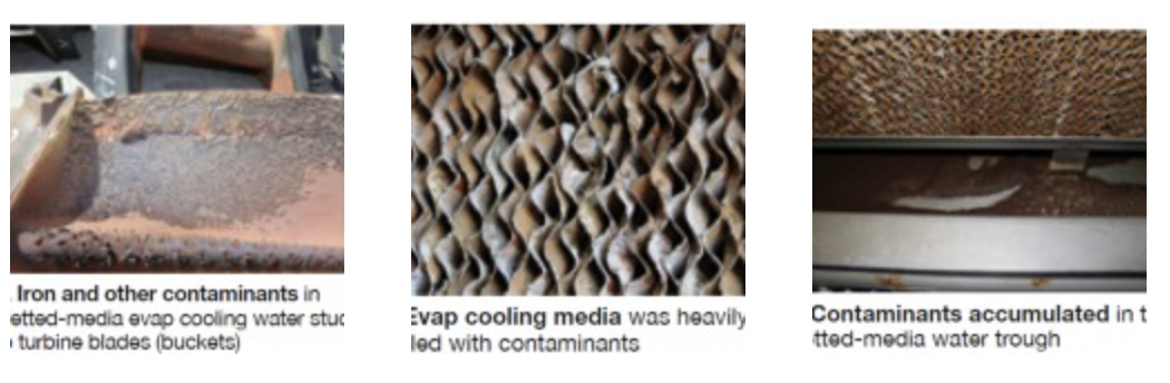
The first case history involved a wetted-media-type evaporative cooling system. Plant personnel, puzzled by the rapid drop-off in electric production within a few weeks after evap coolers were restarted, scheduled an immediate borescope inspection. Deposits found on turbine blades (buckets) were so severe an outage was taken to replace the affected airfoils (Fig 1).
Investigation into the source of the deposits revealed accumulations of iron and other contaminants in the cooling water that were attributed to issues with the water-treatment process. The evaporative media was heavily fouled (Fig 2) and large quantities of loose deposits were found in the water trough under the media (Fig 3).
One common mistake is using demineralized water for cooling in evap media systems. While free of both suspended and dissolved solids, demin is aggressive to the glue that holds the media together, and is not recommended. Depending on the water sources available to the plant, there may be several options—including softened potable water, well water, or blends of these and demineralized water. The most critical factor is that the water must be free of suspended solids, he said. At some GT user-group meetings attended by the editors, plant personnel sometimes suggest a 50/50 mixture of demin and city waters for inlet cooling service, but blending streams will require regular monitoring. Analysis showed calcium, magnesium, aluminum, silicon, and iron in the deposits that would have come primarily from the makeup to the evap cooling water. Daniels believed that solids resulting from water-treatment process upsets collected on the media, flaked off, and got sucked into the compressor. The dry deposits formed a mixture that softened at temperatures reached in the combustion section, became sticky, and stuck on downstream airfoils.
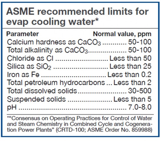 Daniels urged users to redouble their efforts to filter out suspended solids from evap cooling water and to install and diligently maintain filters on evap-cooler recirculation pumps where they do not exist. He then displayed the cooling-water specs for this service as recommended by ASME (Table). Daniels closed by suggesting users also check with their media suppliers to see if they have additional requirements for cooling water.
For a backgrounder on cooling of GT inlet air—including evap coolers, fogging systems, and chillers—read the special report on inlet-air systems in the 2Q/2010 issue, available at www.ccj-online.com.
Bugs foul water circulating through mechanical chiller system
A generating station with two 2 x 1 F-class combined cycles in a hot and humid area of the country uses chilled water to cool compressor inlet air. To maximize power send-out during the daytime hours, the plant relies on a 6-million-gal thermal storage system to virtually eliminate the need to run mechanical chillers on-peak. During the cool months, when the chillers are not required, the system is winterized by flushing a glycol/water mixture through the coils before sealing up the system until spring.
Daniels said biofouling occurred in this chilled water system within a couple of years of commercial start and the presence of sulfate-reducing bacteria (SRB) was confirmed. The dilemma, he continued, was how to effectively treat a 6-million-gal concrete storage tank. He asked rhetorically, “What biocide do you use and how often to you treat the water?”
The water consultant concluded that complete treatment of the water inventory was impractical. There was no cost-effective way to sterilize a 6-million-gal concrete tank. So the solution focused on removing biofilm from the chilled-water piping and coils, where it has greatest impact. Chlorine dioxide was selected as the biocide because of its potency and effectiveness at high pH. The system is treated with this very strong oxidizing biocide in the spring and fall and at other times, as necessary.
FAC 2013: Mark your calendar
Unless you are regularly inspecting susceptible areas of heat-recovery steam generators, air-cooled condensers, and condensate systems for flow-accelerated corrosion (FAC), you’re apt to be surprised one day by the significant loss of material from critical components. This despite the good report on the quality of cycle water received regularly from your chemical supplier.
Think of FAC as analogous to human disease. Everything might look fine on the surface, but underneath there may be serious concerns. It’s important for plant managers to come up to speed on this insidious damage mechanism: Early identification and mitigation are important to maintaining top plant performance.
The 2013 International Conference on FAC in Fossil and Combined Cycle/HRSG Plants will be held March 26-28, 2013 at the Westin Arlington (Va) Gateway hotel. Many of your colleagues will be there to listen to the world’s leading subject-matter experts and to participate in meaningful group discussions. Co-chairs for the meeting are Barry Dooley and Kevin Shields of Structural Integrity Associates Inc. Conference brochure is at www.ccj-online.com/fac2013. For updates, as they become available, and to register, visit www.facfossilhrsgconference.com.
The first FAC meeting, held in 2010, was attended by 170 scientists, engineers, and powerplant personnel from 21 countries and featured a technical program with 40 papers. Read David Addison’s conference summary in the 2011 Outage Handbook, available at www.ccj-online.com/archives. Addison heads Thermal Chemistry Ltd, a New Zealand consultancy specializing in the management of powerplant water chemistry.
Glycol leak wreaks havoc with cycle water chemistry
“No good deed goes unpunished,” as the saying goes. That certainly was the case at a large plant equipped with four new LM6000 peakers, three conventional gas-fired steam units, and a 2 x 1 combined cycle. Demineralized water is produced by two independent systems: packed-bed ion exchange and reverse osmosis/mixed-bed demineralizer.
While most plants send their air-chiller condensate to drain, this facility suggested recovering it and using the nearly 170 gpm of pure water collected to reduce the amount of raw water withdrawn from wells supplying the plant with makeup. During the summer months, the quality of the low-conductivity demineralizer makeup recovered was excellent.
In February 2011, during a bitter cold snap, an improperly mixed glycol/water blend froze and tubes ruptured. Repairs were made and plant personnel believed “everything was back to normal.” But about six months later, the hibernating gremlins awoke in the IP drums of both HRSGs; pH dropped to the mid 7s and stayed there.
There also was a slight pH depression in the HP drums and steam/condensate cation conductivity jumped up. However, there was no significant increase in sodium or chloride in the condensate, thereby eliminating a condenser tube leak as the cause. Both HRSGs were removed from service, drained, and refilled.
Day 2: Similar contamination symptoms (pH and cation conductivity) appeared in the gas-fired steam units. The source of that contamination was identified as glycol in the condensate being returned to the service-water tank supplying the ion exchangers.
Day 3: The HRSGs had the same pH and cation-conductivity problem when restarted because they were filled with glycol-contaminated water before the source was identified. After one more cycle of flush and fill, the contamination was eliminated.
Lessons learned:
- Organic contamination causes unusual chemistry symptoms.
- A little organic contamination goes a long way and takes a long time to clean out.
The plant has not given up on using condensate recovered in the air inlet house as a source of demineralizer makeup. But it will add a fluorescent dye to the glycol and install a fluorometer on the condensate-tank pump discharge to warn quickly of a leak. Interestingly, a sister plant also recovers moisture from the air, but it uses that condensate as cooling-tower makeup. This creates other interesting issues in cooling-water chemistry and corrosion. CCJ