


Clashing, controls, refurbishment of hot parts top topics for ageing fleet
Conferences of the 7EA Users Group traditionally begin with a State-of-the-Engine report by Advanced Turbine Support LLC, Gainesville, Fla, the inspection specialists who rely on borescopes and an assortment of nondestructive examination (NDE) tools to check annually the internal condition of more than 1000 gas turbines of all types. ATS is respected industry-wide for sharing its findings to help all users.
At the 2012 meeting of 7EA owner/ operators held late last October in Greenville, SC, the Steering Committee’s senior member, Pat Myers, plant manager of AEP’s Ceredo Generating Station, introduced Advanced Turbine Support President Rod Shidler and Service Manager Mike Hoogsteden to deliver their yearly assessment.
As Hoogsteden dug into the details, it became apparent that the number of issues identified each year in the ageing fleet is increasing. It’s more important than ever, he said, to perform inspections regularly and properly to prevent “issues” from developing into catastrophic losses. Then Hoogsteden stressed the need for owners’ engineers to review promptly documented findings and to develop and implement programs to mitigate identified risks.
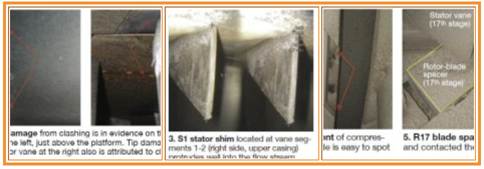
Clashing. For many attendees, the highlight of the presentation was ATS’s five-step clashing mitigation procedure that Hoogsteden introduced to the group. Recall that clashing—the term used to describe contact between rotating blades and stationary vanes in Frame 7 compressors—has been a hot topic for years at the 7EA meeting. The service manager said that ATS inspectors have documented clashing damage to the trailing edge of R1 rotor-blade platforms (Fig 1) and the leading edge of S1 stator vane tips (Fig 2) for the last five years. More importantly, accurate measurements of the damage have been taken over the last three years and records maintained for each affected vane using the OEM’s stator-vane numbering system. In several cases, data have revealed increases in clashing damage over time.
1. Check for clashing damage during your regular semi-annual or annual borescope inspection.Absent a Technical Information Letter (TIL) on how users should address clashing damage, ATS offered the following procedure:
2. Perform an in-situ red-dye penetrant inspection on the trailing-edge platforms of rotor blades, stator-vane tips, and on the convex side of stator vanes where damage is in evidence.
3. Blend/crop in-situ the affected airfoils. The extent of the repairs is determined by the type of damage identified during the first two steps.
4. Apply in-situ an approved lubricant/rust inhibitor to the platforms of damaged stator vanes. Note that current industry thinking is that vane lock-up attributed to rust and other airborne debris is at least partially responsible for clashing.
5. Monitor/trend results. Appropriate intervals for follow-on inspections would be determined by the extent of the mitigation process implemented.
TIL review. Hoogsteden spent most of his time at the podium discussing what ATS believes are the OEM’s most important TILs regarding the 7EA compressor. Much of this information had been presented previously and covered in past issues of CCJ ONsite, but more than half of the 120 or so attendees were first-timers and the review was particularly valuable. The following is a list of the TILs covered and the issues they addressed, with publication dates in parentheses:
• 1132-2R1, spring and thrust washers for variable inlet guide vanes (Dec 15, 2004).
• 1562, stator-vane shim migration (Jan 30, 2007).
• 1854, compressor R2 and R3 tip loss (Aug 27, 2012).
• 1090-2R1, R17 blade movement (Mar 3, 1993).
• 1744, stator-ring rail and CDC hook-fit wear in stages S17, EGV1, and EGV2 (Sept 27, 2010).
Photos incorporated into Hoogsteden’s comments on typical IGV damage, illustrating rubs against the inlet bellmouth and bending of inlet guide vanes, had already appeared in CCJ ONsite. Shim migration (TIL 1562) has been discussed extensively over the last several years in the pages of the quarterly CCJ. Using the Google-like search feature available at the top of the page you can find a wealth of information on the subject, including valuable user experience. Hoogsteden gave the group an ATS rule of thumb: When a shim protrudes 250 mils or more into the flow stream (Fig 3), it almost always can be removed. If removal is not possible, the shim is trimmed flush with the stator-vane platform.
The service manager mentioned that the week prior to the 7EA meeting, an ATS inspection team found ½-in. cracks on two pristine rotor blades—that is, there were no tip rubs and no discoloration in evidence. Hoogsteden said the company’s recommendation was to do a dye- penetrant exam during each inspection to monitor crack growth. Tip grinding is not necessarily the solution, he added, recalling indications of cracking on 18 blades during the first inspection following tip grinding of that blade row in the shop. A red-dye check adds only a little time to a regular borescope inspection because all R1 and R2 compressor blades, and about 85% of the R3 blades can be accessed in-situ.
Regarding TIL 1090-2R1, Hoogsteden said the biggest concern is how much the R17 rotor blade is moving forward. The Friday before the service manager addressed the 7EA users, an ATS inspector reported that upstream movement of an R17 rotor blade spacer allowed it to contact the rotor, despite double staking. Blade and spacer movement shown in Figs 4 and 5 was 100 mils; maximum allowed is 10 mils.
| 1. Know your 7EA turbine
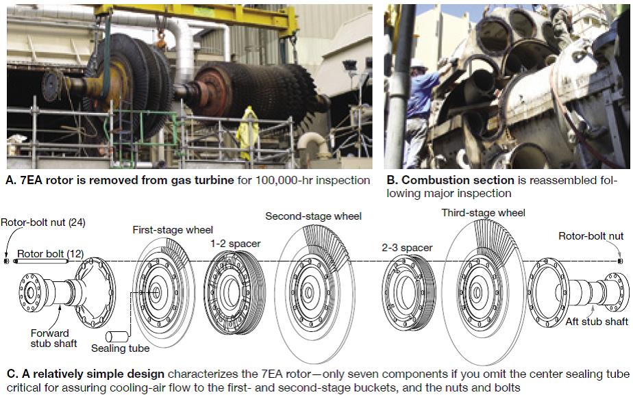
With more than half of the owner/ operators participating in the 2012 Conference of the 7EA Users Group first-timers, one had to believe that many of them never saw the rotor out of the casing. Consider what follows an “orientation” program to help you get to more familiar with your 7EA workhorse. The nominal 85-MW 7EA gas turbine, which first entered service more than 30 years ago, has been used in a wide variety of utility and industrial electric-generation and mechanical-drive applications. As a power producer, it features a single rotor with the generator connected to the gas turbine at the “hot” end (Fig A). The 17-stage axial-flow compressor, equipped with modulating inlet guide vanes and having a pressure ratio of about 13:1, is bolted to the turbine section. The three-stage turbine is of relatively simple design. Its job is to convert energy from the hot pressurized gas exiting the combustion section to mechanical energy (Fig B). The rotor assembly consists primarily of a forward stub shaft, three turbine wheels, two spacer wheels, and the aft stub shaft, which includes the journal for the No. 3 bearing. Each turbine wheel is separated from the adjacent stage, or stages, by a spacer wheel. The wheel separating the first and second stages is known as the 1-2 spacer, that separating the second and third stages the 2-3 spacer (Fig C). The spacer-wheel faces have radial slots for cooling-air passages; outer surfaces are machined to form labyrinth seals for interstage gas sealing. Selective positioning of rotor members is performed during assembly to minimize balance corrections of the assembled rotor. Concentricity control is achieved with mating rabbets on the turbine wheels, spacers, and shafts. Rotor components, held in compression by 12 bolts, are cooled by air extracted from the 17th stage of the compressor. This air is used to cool the turbine first- and second-stage buckets, plus the rotor wheels and spacers. The first-stage buckets rely on forced-air convection cooling in which turbulent air flow is forced through integral cast-in serpentine passages and discharged from holes at the top of the trailing edge of the bucket. Buckets in this row also are coated for corrosion protection. Second-stage buckets are cooled in similar to those in the first stage. Third-stage buckets do not require forced-air cooling. Second-and third-stage buckets have integral tip shrouds that interlock the airfoils to provide vibration damping; they also have seal teeth to reduce leakage flow. Buckets are attached to the wheel with fir-tree dovetails that fit into matching cutouts in the rim of the turbine wheels. The rotor assembly is arranged to allow bucket replacement without having to unstack the wheels, spacers, and stub-shaft assemblies. Similarly, buckets are selectively positioned such that they can be replaced individually or in sets without having to rebalance the wheel assembly. Three stages of turbine nozzles complement the rotating buckets. First- and second-stage nozzles, consisting of 24 segments of two vanes each, are cooled by a combination of film, impingement, and convection cooling. Third-stage nozzle segments number 32 (two vanes in each) and are not cooled. The turbine shell provides internal support and axial and radial positions of the shrouds and nozzles relative to the turbine buckets. This positioning is critical to GT performance. Borescope ports are provided for inspection of buckets and nozzles. The exhaust frame is bolted to the aft flange of the turbine shell and consists of outer and inner cylinders interconnected by radial struts. The inner cylinder supports the No. 3 bearing, while the tapered annulus between the outer and inner cylinders forms the axial exhaust diffuser. Cooling of the exhaust frame, No. 3 bearing, and diffuser tunnel is accomplished by independent motor-driven blowers.
|
‘Business as usual’ controls strategy still works for many users
Gas Turbine Controls Corp’s Peter Zinman, participating in a panel focusing on control-system maintenance and upgrades, suggested to owner/ operators that they basically had four controls strategies to choose from: Upgrade to the OEM’s latest system, upgrade to Ovation™, replace the turbine, do nothing. There’s at least one other retrofit option, of course, a PLC-based controls solution, but it was not included in this session.
Gas turbine reliability is everything: If you don’t start, you don’t get paid. The safe bet for a 7EA owner is upgrading to the Mark VIe, but that’s the most expensive option and probably unaffordable for most plants. Upgrading to Ovation is less expensive, the editors have been told by users, and that has become a popular solution even for some Frame 5 owners.
Replacing the turbine probably is unrealistic given the cost and the permitting challenges. Doing nothing obviously is the least-cost option and viable only if the engine starts when you push the button. The task facing three of the four panelists was to convince attendees that there was a supply-chain network to support a “do nothing” philosophy. And they did that well.
With the OEM having had the entire first day of the meeting on an exclusive basis to capture hearts and minds, there was no need for a GE participant on the panel. Emerson Process Management’s Ovation product line was represented by Patrick Nolan, director of gas turbine solutions, and well known to many in the room. Zinman’s company, and Randy Riggs’ PowerGenics, offer overnight delivery of replacement control system cards from their extensive warehouses as well as the capability to repair failed cards.
CEO John Downing’s Turbine Controls & Excitation Group Inc represented the field-service community—the hands-on experts who do the troubleshooting, repairs, upgrades, and enhancements required to support turbine operation. Other companies providing the same services as Downing’s were represented at the Vendor Fair, such as CSE Engineering Inc.
Nolan was the odd man out among the presenters, supporting the idea that a new, modern control system really was in the best interest of owners. NERC’s Critical Infrastructure Protection Standards (CIPS) will drive many control retrofits, he said, adding that it will not be acceptable to keep Mark V and earlier systems in service.
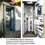
Nolan was convincing regarding the relatively simplicity in swapping out control systems. Emerson’s approach, he said was to remove the old cabinet and drop into the existing space (in most cases) a new Ovation cabinet, which can be completely pretested in the supplier’s manufacturing plant (Figs 6, 7).
 The company’s policy is to deliver new graphics well in advance of the factory acceptance test so operations personnel can comment and Emerson can make the mods requested before the FAT. A simulator is used during the FAT, the controls expert continued, to mimic actual operation. He discussed the value of simulation in terms of time saved on the conversion of multiple 7EAs at one site from Mark IV, dual fuel, water injection to Ovation.New drawings come with the replacement control system, Nolan noted, because accurate documentation is critical for troubleshooting. By new drawings, he meant they go back to the source so the OEM’s drawings, which probably were never updated to reflect changes over the years, can be tossed.
For those considering control-system replacements, Nolan suggested they think seriously about upgrades which can add considerable value at relatively little cost. Flame detection was one of the upgrades suggested. Legacy systems from a couple of the traditional suppliers of that equipment are oft cited at user-group meetings for reliability issues. By contrast, modern systems, which do not require water cooling, reportedly are very reliable.
Upgrades for tighter control of NOx water injection was another suggestion. Generator monitoring is yet another area where upgrades are beneficial because they allow you to deep-six all of the old transmitters and transducers. New vibration controls were recommended as well. Nolan also suggested eliminating the overspeed bolt if installed.
Riggs spoke briefly about PowerGenics’ capabilities in the repair and upgrade of control cards for GE gas and steam turbines, focusing on the Mark IV, V, and VI, which are of greatest interest to 7EA users. He mentioned the cards his firm repaired most often, good intelligence for users contemplating spares they might want to have on-hand. Interestingly, the power supplies for the Mark V and VI were the top concerns for those control systems. Overspeed-trip cards for the Mark V also were said to be failure-prone.
The repair expert suggested to attendees that they look for cracks in resistors when they’re inspecting and troubleshooting power supplies. If you find cracks, he said, change-out the power supply and have the one removed repaired—because it will fail, it’s only a matter of time.
Analyses by PowerGenics of repairs made to power supplies suggests that cycling and overload conditions, plus heat and airborne dirt, are among the primary causes of stresses that contribute to their failure.
Another troubleshooting tip: Cards get noisy before they fail. Replace quickly, Riggs continued, because they can contribute to the failure of other cards—a cascade effect of sorts. One of the biggest troubleshooting challenges, he said, were intermittent faults that go away before you can find them.
PowerGenics technicians maintain detailed records on all repairs. This information enables the company to prioritize the causes of failures and to identify weaknesses in components used in the manufacture of the original control cards. Marginal components are replaced with more robust offerings during the repair cycle making refurbished replacement cards better than the original—at least in some cases.
Zinman was prepared to say much more than he did, but because Gas Turbine Controls and PowerGenics do many of the same things, he spared the owner/operators repetition. He did drive home the fact that the “do nothing” option for owners regarding controls benefitted plants with experienced I&E techs or access to them through a third-party services firm.
The cons associated with a controls upgrade, Zinman said, include the possibility of an extended outage, training of personnel unfamiliar with the new system, operational risks following re-commissioning, high cost compared to doing nothing, purchasing new spares, and the sale or disposal of old parts with no use at the plant upgraded.
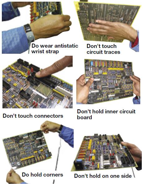
A few years ago, Zinman presented at the 7EA Users Group meeting on the dos and don’ts in the handling and storage of circuit boards. This material is as valuable today as it was when first presented, and given the large number of first-timers at the 2012 meeting, is worth reviewing (Sidebar 2).
Downing didn’t miss a beat while roaring through a presentation on Mark V troubleshooting basics, best practices, and lessons learned. Ex-navy and a former field engineer for the OEM, he left no doubt regarding his deep knowledge and experience. Everyone in attendance with responsibility for a Mark V benefitted tremendously; the editors were among those left in the dust right out of the gate. Among the suggestions made by Downing that the editors could get their arms around included the following:
• Know were all your instruction books are and use them.
• Replace cards with the panel energized, when possible. Before powering-down a cabinet, know what will happen. For example, you lose turning gear and emergency equipment. Also, anyone in the turbine compartment will hear equipment making unfamiliar sounds; the entire plant staff should be informed before de-energizing a panel.
• TMR (triple modular redundancy) is a buzz acronym that the OEM likes to use. It sounds important and leads some owner/operators to believe that their control system is of the highest reliability and essentially failure-resistant. Not! The cabinet is TMR, but not all the devices. In fact, relatively few devices—perhaps as few as 5%—are truly redundant.
• Control cabinets are much like closets. Close the door and everything seems in order. At some plants nothing could be further from the truth, dirt and loose wires abound. Periodic “clean and inspects” are necessary. Every year or two, site technicians should vacuum inside cabinets, tighten connections, conduct necessary calibrations (read the instruction book). Such work enables plant personnel to get (or remain) familiar with system components. This pays dividends when problems surface: Experts can walk knowledgeable plant technicians through the system by phone in many cases, saving time and money.
• A rule of thumb: Recalibrations of control components can deliver as much as a 1% increase in turbine output.
• Install fuses, where possible, to protect circuit cards. A $1 item is all it takes to protect a $5K circuit card from some failure mechanisms. Most of the work can be done with the unit online; final connections, which should take no more than about two days, are made during the next outage.
The take-away. The presentations by Zinman, Riggs, and Downing were complementary, creating in the minds of attendees that a tight network of reliable third-party equipment and services providers was only a phone call away when problems surfaced with legacy GE control systems. If PowerGenics doesn’t have a card a customer needs, Riggs calls Zinman—and vice versa. If Zinman doesn’t have field service personnel available for a particular assignment, he calls Downing. And if Downing doesn’t have control cards for a project his firm is hired to do, he calls Riggs and/or Zinman. The bottom line: These competitors, at least, believe the customer’s needs come first.
| 2. Handling circuit boards: Dos and don’ts to remember
Reduce environmental static If possible, and to the extent practical, maintain a heightened level of humidity around the control panel and other areas where boards may be handled. • Ground your panel. A properly grounded panel helps prevent the buildup of static charges and can dissipate built-up charge from the operator. • Avoid wearing clothing that easily generates or stores static electricity. Cotton or cotton blends are recommended, synthetic or woolen materials are not. • Plastic items have the potential for generating a static charge. Keep all plastic and Styrofoam™ items away from any area where circuit boards are handled. Ground yourself When handling a circuit board, the operator should be properly grounded by (1) wearing a wrist strap connected to a grounding device, or (2) wearing heel grounders while standing on a static dissipative floor surface or mat. In the absence of either, always discharge any static charge your body might have built up before handling a circuit board. This can be done by touching a grounded metal object—such as a grounded electrical outlet—and holding it for at least two seconds. If your panel is grounded, that will work too. Wearing an antistatic laboratory coat also can reduce the risk of static discharge to the board from clothing. Handle equipment correctly • Do not touch components, circuit traces, or connectors on a circuit board. Handle circuit boards by their edges. Never hold a card in the horizontal position by one edge; the resulting stress can damage the circuitry. • After a circuit board or module is removed from a control panel, promptly store it in an antistatic protective bag or box. • Do not store circuit boards in a stack or adjacent to each other because this also can damage the components. |
Metallurgy that translates to a stronger bottom line
Plant directors, operations managers, maintenance managers, and plant engineers rank high among Planet Earth’s most time-challenged professionals. They are expected to run their minimally staffed facilities at top efficiency and reliability without violating emissions permits—all while protecting personnel from injury, dealing with an endless tsunami of corporate and regulatory paperwork, reducing expenses, planning the next outage, etc. Plus, they have to grow in their jobs and learn new technologies—metallurgy, chemistry, cybersecurity, etc—to assure continued success.
The editors often are asked about the value proposition of user groups, some narrow-minded executives believing they’re merely an excuse to miss a week’s work. Nothing could be further from the truth. They are venues for professional growth with a payback for employers many times the cost of the registration fee, plane ticket, and hotel.
Case in point: The 7EA Users Group, helped owner/operators come up to speed on the role played by metallurgy in making better decisions regarding the repair of gas-turbine hot parts. Who at your plant can look at a photomicrograph and understand the condition of the material and whether it can be restored to operational health? Probably no one—and that’s fine. But someone has to know the lingo and enough about the subject so the experts can be asked the proper questions, their answers evaluated, and decisions made.
Liburdi Turbine Services’ Lloyd Cooke was selected by the steering committee to provide a backgrounder on both metallurgical analysis and deterioration mechanisms that affect gas-turbine hot parts and then to explain how plant personnel should use the findings of component assessments to guide remedial/preventive action.
Cooke, who speaks technology in plain English, began by making the users aware of the incentives for maximizing component lives, reliably, through informed metallurgical analysis. Aside from fuel, he said, component life-cycle costs are the most significant gas-turbine O&M expense—and hot-section components are at the top of that list. Single sets of components—buckets or nozzles in the case of GE machines—can run from about $800,000 to $2 million per set.
Development of the optimal maintenance program to suit your plant’s specific requirements requires the answers to many questions, Cooke continued, including these:
• Is the component repairable by conventional means?
• What repairs should be completed to assure continued service?
• Are there modifications/upgrades better suited to the engine’s operating conditions—such as addition of a coating or a coating change?
• Are there engine issues that should be known and/or corrected?
• Can the service interval be extended?
• Is the service duty experienced by the parts going to change?
• How can hours and starts be related to fundamental material changes and measurements of degradation?
Metallurgical life analysis of hot-section parts goes beyond the science of metallurgy, Cooke explained. It requires information on the component’s operating history, knowledge of service conditions expected in the future, dimensional data, and findings from nondestructive tests—in addition to the results from the destructive examination of samples removed from specific areas of interest, microscopic examination, chemical analysis, and mechanical testing. These data are analyzed by experts to do the following: • Gauge repairability and define the repair processes.
• Minimize the risk of otherwise undetectable damage.
• Evaluate coating performance/selection specific to your plant’s needs.
• Provide indications of abnormal/ detrimental engine operating conditions.
• Assess the potential for extending the service interval.
• Validate repair processes and/or design improvements.
Next, Cooke dug into the causes of base-metal deterioration—such as alloy ageing, creep damage, and the formation of topologically close-packed phases (don’t get derailed by the jargon)—moving from there to bucket tip oxidation (material loss), thermal-mechanical fatigue damage, etc. Several slides that followed were dedicated to metallurgical analysis of coatings—including discussion of the most common degradation mechanisms, oxidation, and corrosion.
Damage to internal surfaces of buckets (both coated and uncoated) was next and very important, Cooke said, adding that internal damage can eliminate the option of repairing parts. Destructive metallurgical analysis of a representative sample from the set is necessary to determine the extent of internal damage and if continued service is possible. “Make metallurgical analysis part of your maintenance program,” covered most of the points Cooke made in his presentation and is recommended for follow-on reading.
The hot-parts refurbishment expert concluded his presentation with several performance improvement mods for users to consider, among them:
• Consider first-stage bucket tip extensions as an alternative to replacing shroud blocks with the OEM’s low-profile shroud clearance mod. Liburdi claims a 500-kW increase for this enhancement.
• Reduce tip clearance with a MCrAlY high-porosity top coat on uncooled shroud blocks. The coating is abradable and oxidation resistant.
• Cutter-tooth upgrade. Friction between the rail/cutter tooth is conducive to high temperatures that allow transfer of rail material to the honeycomb. Result is rail disintegration. The OEM’s cutter tooth is cast into the buckets as new, meaning it is the same nickel-based alloy as the bucket. The upgrade is Stellite hard-face weld alloy.
• Combustor material upgrade. Substituting Nimonic 263 for Hastalloy X can increase high-temperature strength. Plus, Class C TBC (thermal barrier coating) increases thermal protection without sacrificing thermal strain.
With lunch approaching, Cooke left the podium asking users to evaluate rigorously the hot-section component life-extension alternatives he presented. Comparing the service lives and performance of enhanced components to the OEM’s data presented in its document GER 3620, he said, Liburdi believes owners can save upwards of $12 million over 20 years.
GTs, like people, sag with age
When Paul Bruning stepped to the podium to share recent overhaul experiences, it had been five years since he last attended one of the organization’s meetings. The former chairman of the group’s steering committee recognized only a handful of the nearly 120 users facing him and he was surprised. So, before starting his presentation, Bruning asked the audience how many owner/operators were attending for the first time. By show of hands, it was more than half of the participants. That’s turnover with an exclamation point.
Bruning chaired the user group for three years while he managed the Sumas Power Plant, a 1 ×1 7EA-powered combined-cycle cogeneration facility that provided steam to a Washington mill for drying lumber. When his employer, Calpine Corp, was forced into bankruptcy, Bruning moved to Puget Sound Energy (PSE) in Bellevue, Wash, as supervisor of thermal engineering.
At that time, the utility was perhaps known best for its hydro assets. But it did have several legacy Frame 7 gas turbines, which were the subject of Bruning’s presentation. In the last several years, Puget has added substantially to its thermal fleet by purchasing both peaking gas turbines and combined cycles—including Sumas.
PSE owns four dual-fuel 7Es—all installed in 1981 and each capable of producing 80 MW within 10 minutes after starting. Two units are at the Whitehorn Power Plant in Blaine, Wash, on the Canadian border, two at the Frederickson Power Plant in Tacoma.
Major inspections were performed on the Frederickson units in 2010 and 2011. At the time of the inspections, each unit had logged approximately 18,000 fired hours and 900 starts since COD. Service duty was characterized as peaking and spinning reserve. Water injection for NOx control was heavy—about 90 gpm per unit.
The majors on Frederickson Units 1, conducted first, and 2 included the following tasks: • Disassembly of the gas turbine, generator, and auxiliaries.
• Replacement of compressor blading.
• Replacement or refurbishment of hot-gas-path components.
• Implementation of outstanding TILs.
• Refurbishment of most balance-of-plant components.
• Generator inspection, replacement of retaining rings, rewedging of stator coils, and reblocking and tying of end windings.
• Replacement of the exhaust system.
High bearing vibration levels were experienced by Unit 1 on restart following the major. The third-party services firm that did the major huddled with the OEM regarding the issue and both agreed that misalignment was the likely cause. Unit 1 was reopened under warranty and its alignment checked by Cascade Machinery Vibration Solutions, specialists in this type of work. The compressor discharge casing (CDC) was found to be low and the No. 3 bearing high (Fig 8).
The contractor that conducted the major raised No. 2 bearing and lowered the No. 3 bearing to bring them in alignment with the machine axis. Vibration levels after reassembly were acceptable although the as-left alignment was a compromise given the age of the unit, the time available, and budget considerations. Cascade Machinery’s Troy Broussard was on the program later in the day and explained to the users how the alignment was done.
Bruning, joined at the podium by Evan Sorrel, Frederickson’s O&M Supervisor, said no one expected casing alignment to be a problem. It was not checked on the two Whitehorn units during majors on those engines before the Frederickson work began and vibration was within spec on restart.
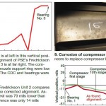 During its three decades of service, the Frederickson gas turbines had long periods of inactivity; more recently, the units had experienced tough service, starting twice on some days. One of the twice-daily starts often involved loading to 4 or 5 MW, followed by shut down.Wear and tear of compressor blades at Whitehorn, plus corrosion of Frederickson compressor airfoils (Fig 9), convinced PSE to replace compressor blades at the Tacoma facility.
The OEM conducted the major on Unit 2 the following year and its recommendations in TIL 1819, which concerns slippage at flange between the turbine shell and exhaust frame, triggered an alignment check (Fig 10). Slippage between the bellmouth and compressor case also was investigated. Alignment was corrected by the OEM this way:
• Inlet bellmouth, inner barrel, and CDC were raised.
• No. 3 bearing was lowered and moved slightly to the right.
• As-left alignment, although not within specs for a new unit, was approved by the OEM as appropriate for a unit of this age—as it was for Unit 1.
• Vibration levels have been low since completion of work. CCJ