


Concrete wall facilitates cleanout of cooling-tower basin
Challenge. Rathdrum is permitted as a zero-discharge (ZD) facility. As such, the plant does not discharge any process water offsite. Undesirable solids are removed from the various process-water streams by a mechanical process in the ZD area of the plant. A downside of the ZD system is that the plant is not permitted to discharge the large volume of cooling-tower water during outages, challenging staff in the removal of soda-ash solids that accumulate in the basin.
Clean out of these solids during each annual outage is a best practice because it virtually eliminates plugging of plate-and-frame heat exchangers located throughout the plant. Water must go somewhere to allow basin cleanout. We could move some of it to a 100,000-gal waste tank, but this would fall way short of the tower’s 378,000-gal capacity. We would have to rent more than a dozen 21,000-gal Baker tanks at a cost of roughly $5000 per tank to hold the remainder.
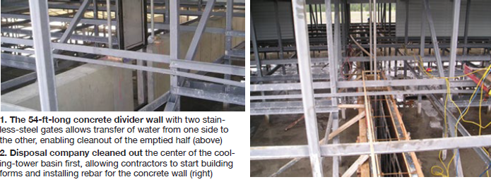
Solution. With help from a local engineering firm, staff came up with a plan to clean the basin without renting Baker tanks. It involved building a 54-ft-long wall, equipped with two 2 × 4 ft stainless-steel gates, to divide the basin in two. With the wall in place, plant personnel could pump all the water out of one half, clean that half, and then transfer the water back into the clean end to allow cleaning of the other half (Fig 1).
To prepare for the project, staff conducted a cooling-tower evaporation test to determine how much water could be evaporated from the tower, and how quickly. A few portable Baker tanks were rented to hold any water that could not be evaporated or transferred to other holding areas within the plant. We also had to remove the sound-suppression chevrons from the tower in order to access the basin.
The plant shutdown went well, and we kept the tower basin temperature at approximately 85F to help with evaporation. We transferred as much water as possible to the holding areas to minimize the amount of makeup needed to refill the tower. The five 24-in.-diam riser pipes added a good deal of volume to the basin’s 378,000 gallons. Additional water flowed back to the tower basin when we began isolating each of the risers, so the Baker tanks came in handy.
To move the remainder of the water once the main circulating pumps had been shut off, we rented a gasoline-engine-powered trash pump with a 3-ft discharge connection and a capacity of approximately 25,000 gal/hr to expedite the transfer.
 After emptying the basin, staff found that the solids measured over a foot deep in some areas. A waste disposal company was hired and its vacuum truck sucked out all the residue and disposed of it. The center of the basin was cleaned out first so the contractor could start installing rebar and building forms for the concrete wall (Fig 2).
Once the wall was completed and the gates installed, staff filled the tower with gates down to test the integrity of the barrier. The gates leaked excessively at first, but held after repairs were made. Next, plant personnel filled the tower to capacity, opened both gates, and started the circ-water pumps to test the flow through the gates. With both circ pumps in service, we achieved a differential level across the wall of between 15 and 20 inches.
After consulting with the engineering firm, plant decided to cut additional weir notches in the wall to improve flow characteristics. Once the staff had transferred water to allow them access, the contractors cut two 3-ft-wide overflow weirs 18 in. deep. We coated the cut surfaces with epoxy to protect the exposed rebar and allowed it to cure overnight.
Once again, we filled the tower and placed it into service. The weir notches seemed to allow adequate flow across the wall; the differential level now measured 2 to 3 inches. We installed two-sided gasketed compression panels over the weir opening to prevent water flow between the two basins during cleanouts.
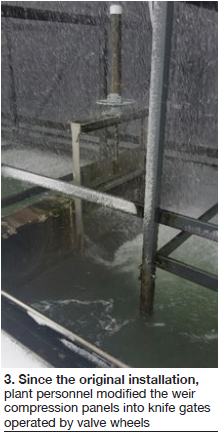
Results. Since the original installation, we’ve modified the weir compression panels into knife gates operated by valve wheels (Fig 3). These allow the gates to be fully compressed into their channels, further reducing any leakage between the two halves of the basin. We recouped the original cost of building the wall—$15,000—the following year, because we no longer had to rent Baker tanks for storage. Overall, this upgrade has greatly improved our annual planning, staging, and cleaning of the facility’s cooling systems.
Project participants:
Tim Mortimer, maintenance supervisor
Mark Villagomez, lead maintenance mechanic
Steve Woolley, EHS supervisor
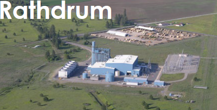
Rathdrum Power Plant
Owned by Tyr Energy
Operated by NAES Corp
275-MW, gas-fired, 1 × 1 combined cycle located in Rathdrum, Idaho
Plant manager: Gary Allard