


Editor’s note: At user-group meetings, you often hear owner/operators discuss the benefits of using data captured by the plant historian in failure analyses. The two case histories presented here by engineers from HRST Inc illustrate the value of historical data in finding the root causes of problems identified during inspections of heat-recovery steam generators (HRSGs).
After reading through these short case histories you might ask, “Is anyone at my plant regularly reviewing historian data to identify potential problems before they cause damage, and possibly a forced outage?” This proactive approach certainly seems worthy of consideration.
Leaking valve cause of tube-to-header failures
By Daniel E Acosta, PE
Inspecting heat-recovery steam generators (HRSG) often is like detective work. Given a mystery issue, you need clues to help solve the case. Like a seasoned sleuth, the equipment inspector must know how to distinguish tell-tale signs and use them to identify the culprit. While not all criminal minds or HRSG problems are created equal, a few basic forms of investigation can go a long way in helping to assess a situation.
Aside from the usual visual inspection of HRSG components, valuable information can be obtained by analyzing selected DCS data. Sometimes, a quick review of key points can prove extremely beneficial. This form of investigation helps identify and diagnose a variety of issues—such as performance shortfall, desuperheater overspray, and control-valve leakage.
A recent example where this type of data review proved useful was at a relatively new plant (less than one year of operation) that had experienced several tube-to-header failures in its reheater panels (harps). HRST was charged with solving the mystery of the recurring failures.
First step was a visual inspection of the affected HRSG. At the time of shutdown, plant personnel were not aware of any new active leaks. Yet immediately after opening the internal access doors leading to the crawl space where the reheater panels are located, staff noted puddles of water on the floor—right below where the previous failures had occurred.
Inspectors checked the tube-to-header connections and found a few crack indications near tubes that had been plugged previously. Leaks were confirmed by introducing water into the affected panels.
Knowledge of related problems at other plants having a similar HRSG design led engineers to collect DCS startup and shutdown data from several key spots in the area where failures were occurring. A cursory review of the data gathered revealed several common problems.
Desuperheater hunting, or rapid changes in desuperheater spray flow, was widespread. Hunting commonly leads to thermal fatigue of the spray-nozzle assembly in probe-style attemperators. Graphing the data facilitates problem identification: Desuperheater hunting was immediately noticeable in the Fig 1 chart profiling a startup.
Note, too, that the steam temperature immediately downstream of the reheat desuperheater came near—and in one case even reached—the saturated steam temperature. If possible, steam temperature downstream of the desuperheater should be at least 50 deg F above saturation at all times, and, as a general rule, should never approach within 30 deg F of saturation. When steam temperature downstream of the desuperheater falls below this value, the risk of overspray (unevaporated spray water quenching the pipe and the next stage of tubes) is high. These problems were consistent with the failures currently taking place.
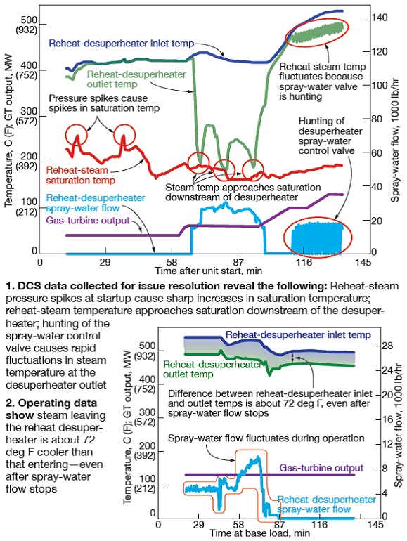
In base-load operation (Fig 2) data revealed a temperature difference of about 72 deg F between the steam inlet to the desuperheater and the outlet—even after spray flow was shut off. This indicated the desuperheater control valve was leaking spray water into the reheat steam line.
Lastly, operating data obtained for the desuperheater control valve showed it never opened above 40% and operated at less than 20% open most of the time it was in use. This indicated the valve was not sized correctly for this application and a smaller control valve was needed. The plant subsequently replaced its desuperheater control valves with ones better suited to the service.
In addition to the issues described in the foregoing example, other problems that can be identified with a review of DCS data include the following:
- Feedwater control/economizer shocking. Are there large fluctuations in steady-state operation? Does the flow start/stop during HRSG startup? Are the drums being topped-off at night, thereby contributing to metal fatigue?
- Automated superheater and reheater drains. Do drains open at the correct times and remain open long enough?
- Drum level. Do the various level indicators agree?
- Drum-temperature ramp rate (can be derived from pressure). Are drum nozzles and manways suffering fatigue damage?
- Overall performance. How do the pinch point, approach point, and stack temperature compare to OEM design values?
- Gas-side pressure drop. Is there a continuous build-up of debris that’s slowly increasing backpressure? Is it time to clean the modules?
Problem-solving 101: Don’t jump to conclusions
By Sam Shaw
Sometimes you have to dig deeper into the detective work to identify not-so-obvious issues. Occasionally, captured DCS data are limited and more information is required to properly diagnose a nagging reliability issue. It’s easy to blame failures on an obvious root cause, but with additional data review, issues initially unsuspected sometimes reveal themselves.
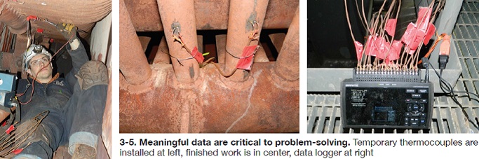
Examples of additional data collection techniques may include the installation of temporary thermocouples (T/Cs) in strategic locations to identify any thermal abnormalities.
Recently, HRST engineers investigated the root cause of several tube failures on a double-wide HRSG installed in 2002. Failures were occurring at the lower tube-to-header connections of the reheater, comprised of two-row, two-pass panels.
Early in the investigation, HRST suspected the observed tube deflection could be a result of the temperature differential between the down-pass (cooler) and up-pass (hotter) tubes. However, it was later verified by inspection that the reheater had spring support hangers (not shown on drawings) to accommodate differential expansion. Additionally, calculations revealed little difference in the temperature of adjacent tube rows. Thus the initial thought of large pass-to-pass temperature differences proved an unlikely source of stress.
Temperature variations across the width of the individual harps then were suspected as the root cause of the failures. The non-uniformity of the observed stresses further supported this theory. The tubes near the center of the harp (in line with the inlet) showed bulging and scale exfoliation. Clearly, data beyond that available from the DCS were necessary.
The required information would come from temporary thermocouples (T/Cs) installed by HRST on the bare sections of tubes in the lower crawl spaces (Figs 3-5). Of primary concern were the temperature differences across the width of an individual harp. Keep in mind that the average temperature of a tube along its length can be calculated knowing the temperature at the bottom of the tube.
The strategy for positioning the T/Cs was as follows:
- Focus on one harp and instrument it thoroughly. Look for differences occurring across the width of the panel.
- Install T/Cs directly under the inlet because those tube revealed they were stressed.
- Install T/Cs at the ends of the harp to identify any issues associated with side-wall or center bypass of turbine exhaust gas.
- Place T/Cs on the drains to spot water that might be flowing in the wrong direction.
- Concentrate instrumentation on down-flow tubes; instrument a small number of up-flow tubes for reference.
- Record temperatures for a cold start, hot start, and steady-state conditions.
 Feedback. Under steady-state and warm-start conditions, the tube-to-tube temperature differences were minimal and unlikely to cause failures. However, under cold-start conditions, temperature differences in excess of 500 deg F were measured between tubes under the inlet and at the side wall. This delta T is more than sufficient to cause stress-induced failures at the tube-to-header connections.
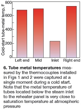
Fig 6 shows the tube-metal temperature measured by installed T/Cs at a single moment during a cold start. Reheater pressure at the time of this event was approximately zero. The measured temperature of the tubes below the inlet drops to just above 200F—close to the saturation temperature at atmospheric pressure. This proves water was entering the tubes and cooling them.
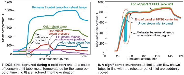
A rookie investigator’s first instinct might be to blame the water infiltration on a leaking or improperly operating desuperheater spray system. But further review of the data suggested otherwise. Fig 7 presents DCS data for the cold start. The information is not particularly troubling by itself. However, when compared to Fig 6, which shows the measured tube-metal temperature of the same period of time, problems become apparent.
Fig 8 reveals a significant disturbance corresponding to first indicated steam flow. The tubes in line with the inlet are cooled suddenly, while those at the ends of the harp are largely unaffected. Refer back to Fig 6 for a snapshot of the temperature distribution during the disturbance.
Engineers believed that improper desuperheater operation likely was not the source of water infiltration. Rather, water was being carried into the reheater with the initial steam flow during a cold start.
Oftentimes the source of such water can be undrained condensate which builds up in steam lines while the unit is offline. Further review of the system revealed there were no drains in the cold reheat piping. Thus any condensate collected in that piping must pass through reheater harps before reaching a drain.
By further investigating the issue, asking more questions, and gathering additional data, engineers were able to identify the root cause of the failures. Lesson relearned: Sometimes the first suspect may not be the one you are looking for. It may take more digging and verification to get the information you want. CCJ