


Schuyler McElrath, the industry’s most vocal proponent of water-cooled liquid fuel systems, assures owner/operators that JASC’s® Gen3 system is capable of approaching 100% reliability during oil starts, and on transfers from gas to oil.
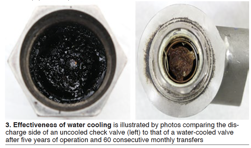
On a recent call with the editors, he ran through the company’s nearly two decades of product improvements and the reasons for his enthusiasm. McElrath pointed to five consecutive years of service and 60 consecutive transfers for JASC’s water-cooled liquid-fuel check valves before an unsuccessful attempt (Fig 3) and seven years of experience with water-cooled three-way purge valves without loss of system reliability.
He began with a description of typical water-cooled systems for units with DLN combustion systems (Fig 4), highlighting the following components and their purpose:
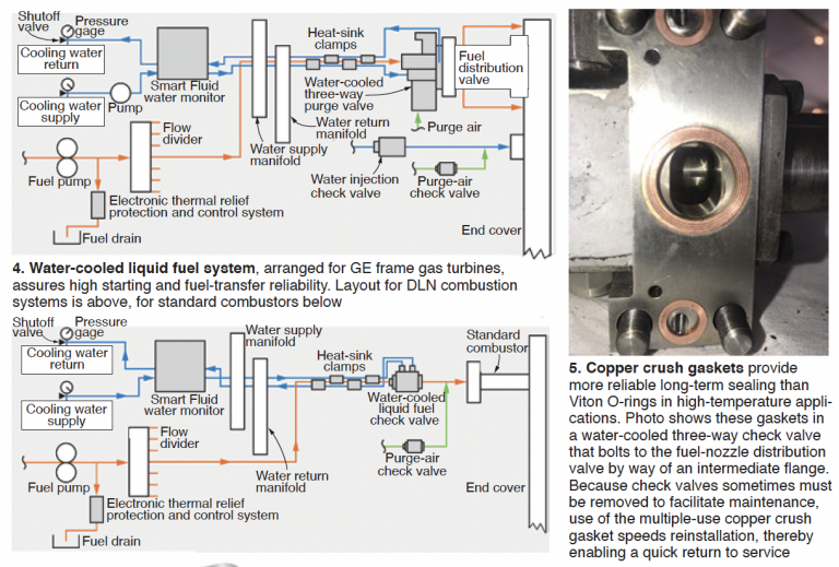
The water-cooled three-way purge valve replaces the uncooled version of the valve, which could plug with coke formed by “cooking” of the liquid fuel when gas was burned.
Perhaps the most significant Gen3 improvement on these valves was the elimination of heat- related O-ring failures on liquid-fuel and purge-air connections through the use of copper crush gaskets (Fig 5) in place of Viton.
While Viton is designed for high-temperature applications, after long-term exposure to heat they lose elasticity, take a set, and crack. The typical result is leakage at joints because of metal expansion and contraction during operation.
JASC’s experience is that copper crush gaskets will survive high-temperature exposure indefinitely with no change to sealing integrity, making them more compatible with today’s extended maintenance intervals. Plus, these gaskets can be made, broken apart, and remade multiple times before requiring replacement.
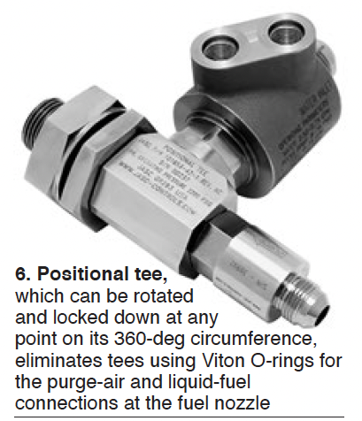
So-called positional tees (Fig 6) are another Gen3 improvement associated with the three-way purge valve. They eliminate tees using Viton O-rings for the purge-air and liquid-fuel connections at the fuel nozzle, opting for copper crush gaskets instead. Positional tees get their name from the fact that they can be rotated and locked down at any point on their 360-deg circumference. The benefit: Three HGP cycles or 12 years of leak-free operation in both peaking and baseload applications.
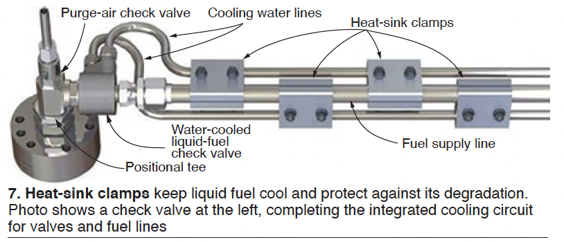
Heat-sink clamps (Fig 7), located just upstream of the three-way purge valve in Fig 4, keeps the liquid fuel system primed from the stop valve to the fuel controls and ready for immediate dispatch. The clamps protect stagnant diesel fuel against viscosity changes which foul fuel control seats and can transition distillate oil to solid coke during extended periods of operation on natural gas.
Water-injection check-valve Gen3 improvements focus on metal-to-metal sealing, thereby eliminating the degradation of elastomeric materials formally used and preventing leakage while on standby during operation on natural gas. Eliminating water-system evacuation on standby avoids exhaust-temperature spreads/trips when water injection is reactivated for emissions control.
The smart fluid monitor shown in the system diagrams was redesigned for the Gen3 system to accomplish the following:
- Measure water supply and return flow discrepancies down to 0.1 gpm.
- Programmable shutoff range of 0.1 to 1 gpm.
- Ability to monitor up to four turbines remotely.
- Standalone control or output can be integrated into the turbine control system.
- Monitor and control cooling-water flow and temperature. A critical function of the smart fluid monitor is to protect the liquid-fuel system against low temperatures associated with paraffin dropout. Recall that wax can impede fluid flow and cause a failure to start.