


Optimizing chiller operation
Best of the Best Award
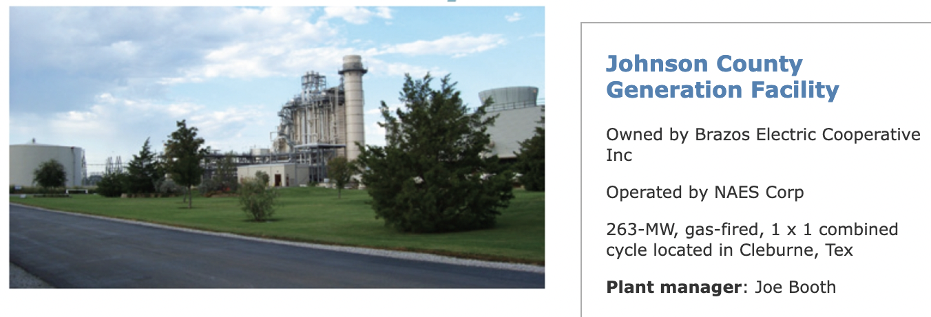
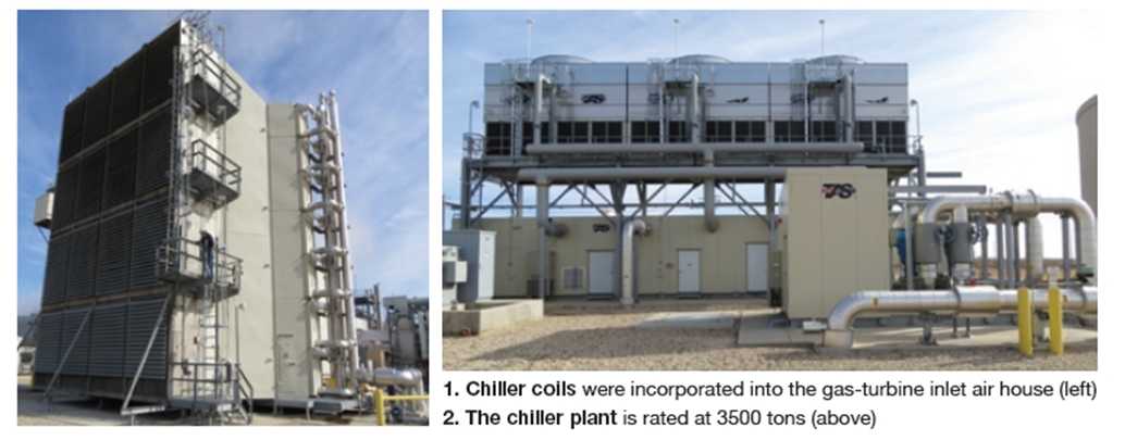
Challenge. While the chiller enabled operators to increase summertime power production and gave dispatchers a predictable output for dispatch, its operation increased station auxiliary load. Another cost to consider: Recharging of the thermal storage tank incorporated into the design of the chiller system. The challenge was to optimize chiller operation for summer peak periods.Brazos Electric Cooperative Inc’s Johnson County Generation Facility, operated by NAES Corp, recently installed a 3500-ton chiller on the front end of the 501FC gas turbine serving the 258-MW 1 x 1 combined cycle (Figs 1, 2). Reason: Dramatic fluctuations in ambient temperature made it difficult for the utility to predict day-ahead generation and gas nominations, and to balance electrical load in its territory in real time.
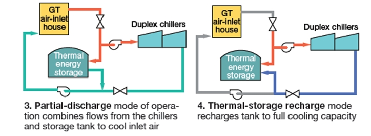
Solution. The system was designed to operate in the “partial-discharge” mode (Fig 3), meaning the total amount of chilled water required for cooling gas-turbine inlet air would combine flows from the chillers and from the thermal storage tank. Over time, the cooling capability of the storage tank would be drained—like a battery in a flashlight left on. The only other mode of operation was “tank-recharge,” which only could be accomplished with no inlet chilling (Fig 4).
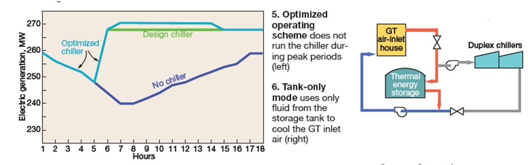
Thinking outside the system design box led plant personnel to what the team believed was the optimal solution (Fig 5). They went against the accepted operations plan in an experiment and took all the chilled water from the storage tank to maintain the temperature set point for turbine inlet air instead of combining flows. This was called the “tank-only” mode of operation (Fig 6).The obvious choice for system optimization: Recharge the tank only during off-peak hours when the cost of power is low and the cycling plant is not in service. The next question was how to efficiently use the capacity of the thermal storage tank. The first step was to create logic in the plant DCS to capture chiller operational data during the different plant operating scenarios through the summer peak season to help guide engineers.
With the VFDs for the thermal tank’s chilled-water pumps able to totally control the inlet set point, the 2-MW house load required to run the chillers could be sold. Since this operating mode would reduce the number of hours the thermal storage tank could operate, plant staff set about deciding how best to use “tank-only” operation.
Results. Data collected provided the length of time the “tank-only” mode could be used while still providing sufficient reserve capacity to allow a return to “partial-discharge” operation to complete the chilling cycle. Typically, “tank-only” chilling is used from about 1 to 8 pm, “partial discharge” from 8 pm until unit shut down.
Project participants:
Vincent Hawkes, operations supervisor
Phil Norman, lead control-room operator
Plant operations personnel
Membrane installation/removal tool reduces physical stress
Best Practices Award
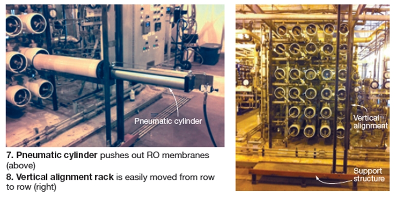
Challenge. Change-out of RO membranes was a physical and time-demanding job. Johnson County’s RO system has 28 membrane cylinders of nominal 22-ft length, each housing six 40-in.-long membranes (Figs 7, 8). This means 168 membranes must be pushed out and new or cleaned membranes pushed back in following a service run. The floor is normally wet with water and glycerin, making the working surface slippery.
 Change-out of membranes required two employees pushing on the membrane train at one end of the tube and two employees on the opposite end to catch the fouled membranes; new or cleaned membranes were installed after the old ones were pushed out. Much of this push/catch effort required reaching above your head or standing on scaffolding.
Safety hazards exist when employees are pushing the used membranes with force, as well as when they are catching the ejected membranes. The chances of strain or sprain exist when the membrane is pushed and depending on amount of pressure, can cause employee to over/under anticipate the outward pressure pushing the old membrane out. The challenge was to control this outward thrust, and apply adequate pressure making each insertion/ejection of membrane a controlled motion, without causing injury.
Solution. The maintenance team certainly has a working knowledge of what is involved in the changing of membranes. Not only are they “hands on” in the work involved, but also active in discussions at safety meetings striving to come up with ideas to maintain or improve the plant’s safety record.
What began as a “what if” drawing on an office whiteboard, became a solution when plant personnel developed a portable air-operated piston and mounting device that aligns with each tube and pushes in the new membrane while pushing out the old membrane. With the new device in working order, the employees only need to load the new membrane on the alignment rack, activating the air piston and retrieving the exhausted membrane at the opposite end. When using the air-operated piston, you can load all six new membranes at once.
The vertical alignment rack is easily moved from row to row by fixed wheels attached at each end of the vertical unit. The piston also is easily moved up and down the vertical unit by inserting it into a machined slot. When not in use, the alignment rack and piston is moved to storage.
Results. The RO membrane installation/removal tooling system cuts two hours of labor off the time previously required for this job. The tool not only eliminates 95% of all physical demands, it has eliminated 95% of the safety hazards of sprains and strains associated with pushing or slipping on the wet floor.
Project participants:
Richard Connally
Michael Starks