


By Steven C Stultz, Consulting Editor
Reminded Dr R Barry Dooley at the Cycle Chemistry and FAC Workshop, sponsored by Structural Integrity Associates Inc (SI), June 27 – 28, 2017, in Cincinnati. Cycle chemistry drives many of the damage mechanisms that affect availability, reliability, and safety of conventional fossil and combined-cycle/HRSG plants, the respected chemist/metallurgist said forcefully. The ongoing battle against operational and financial losses was the motivation for the focused seminar.
“I am not here to make all of you experts in cycle chemistry,” said Dooley who guided the two-day session.“I am here to share experience and insights, to look at strategies, and to give you some key indicators that I hope will reduce future equipment damage, plant downtime, and injuries.
“More specifically,” he continued, “we’ll talk about how all of this applies to your plant, and to your individual jobs.”
And that’s what we did. Interactively. This was a two-day workshop, not a lecture.
The intricacies
Electric power generating facilities are some of the most complex engineering achievements of our time. It’s important to realize that cycle chemistry is equally complex, sophisticated, and at times unforgiving.
Every operating minute of every day adds to the wealth of global cycle-chemistry experience being analyzed by Dooley and the SI team.
Bad habits (poor common practices)
Participants examined what Dooley and his colleagues label repeat cycle-chemistry situations (RCCS)—circumstances that trigger damage. “A focus on RCCS is perhaps the industry’s most powerful tool,” he emphasized.
Dooley added: “Chemistry-influenced failure and damage can always be related back to these repeat situations in fossil and combined cycle/HRSG plants.”
With that, he listed the 10 most common scenarios:
- 1. Presence of corrosion products.
- 2. Drum carryover.
- 3. Fossil waterwall/HRSG evaporator deposition.
- 4. Improper chemical cleaning.
- 5. Contaminant ingress.
- 6. Air in-leakage.
- 7. Lack of online alarmed instrumentation.
- 8. Failure to challenge plant status quo.
- 9. Inadequate shutdown protection.
- 10. Lack of action plans (or simply, lack of action).
Each was discussed in detail.
Consider No. 7, for example, proper instrumentation is clearly outlined in the Technical Guidance Documents (TGDs) available at no cost from the International Association for the Properties of Water and Steam (IAPWS) through the organization’s website at www.iapws.org.
“Very few powerplants throughout the world,” explained Dooley, “meet even the minimum requirements.” Lack of proper instrumentation tied with corrosion products as the leading (and preventable) damage-causing condition.
Summing up the discussion, Dooley emphasized: “We should be able to do something about this, and we can!”
Oxides and growth
It was important to review oxides and their growth (Fig 1) by discussing feedwater, boiler/evaporator water, steam, and deposit formation. A lengthy look at the mechanism of magnetite (Fe3O4) growth showed the importance of feedwater and condensate chemistry. Dooley then focused on magnetite in the LP circuits of both horizontal and vertical HRSGs. This led to discussions of various water treatment programs (Fig 2).
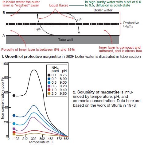
Specific mechanisms of magnetite dissolution, iron oxide solubility, and corrosion-product transport followed.
Copper alloys and their impact on the HP turbine were included, along with a review of supercritical units.
FAC—a complex adversary
Significant time was spent on flow-accelerated corrosion (FAC), a complex yet comprehensible phenomenon in today’s power systems. FAC is the leading cause of failures in combined-cycle plants.
These discussions centered on:
- Single- and two-phase FAC.
- Mechanisms and parameters (very important; solutions are different).
- Alleviation through cycle chemistry and materials.
Dooley offered specific examples of both single- and two-phase FAC in fossil and combined cycle/HRSG plants. The principal point: FAC continues to occur in more than 70% of fossil plants, and represents nearly half of all tube failures in both horizontal- and vertical-gas-path HRSGs.
Fundamental conditions for FAC (formerly known as erosion/corrosion) are processes occurring in the laminar boundary layer on the metal’s surface.
Some details:
- Magnetite is the oxide that grows on carbon-steel surfaces in the feedwater up to about 535F to 572F under low-oxygen (reducing) conditions.
- With laminar flow, this is protective and its growth is balanced by its dissolution.
- Below 302F the layer can be very thin, and is controlled by local cycle chemistries.
- With turbulent conditions (because of local geometries), the dissolved ferrous ions are removed more rapidly.
- This faster removal equates to a more rapid overall corrosion process (FAC) and thinner remaining magnetite.
- FAC only occurs in water and water/steam mixtures, NOT in dry steam.
- FAC is a chemical mechanism.
He then clarified the process. “The normally protective magnetite layer on carbon steel dissolves in a turbulent stream of flowing water (single-phase) or wet steam (two-phase). This process reduces the oxide layer thickness and leads to a rapid decrease in thickness of the base material until the pipe, tube, or pressure vessel bursts (Figs 3 and 4).
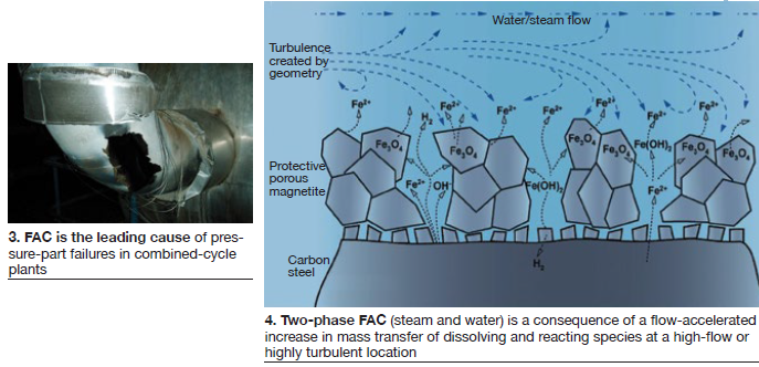
“The rate of metal loss depends, in a very complex way, on three main factors: local water chemistry, material composition, and fluid hydrodynamics.”
Specifics of these processes were clearly illustrated and reviewed, setting the stage for later critical discussions on inspection, appearance, detection and identification.
FAC in air-cooled condensers also was discussed, including specific examples and a review of the Dooley-Howell Air-Cooled Condenser Corrosion Index (CCJ 1Q/2005, p 110). It is used to categorize the degree of corrosion and to track improvements made possible by use of better water chemistry. The relevant IAPWS TGDs were referenced.
Good tubes don’t fail
“Chemistry can be optimized to reduce damage inflicted by FAC,” continued Dooley, as well as that caused by the following damage mechanisms:
- Under-deposit corrosion (UDC).
- Hydrogen damage (remains prolific today).
- Corrosion fatigue.
- Thermal fatigue.
- Pitting.
As Dooley clearly stated, in all cases you must identify the damage and understand the root cause. “You never have a good tube fail,” he said. The key is to understand the damage mechanisms.
Hydrogen damage, based on contaminants, continues to be a major powerplant concern. Damage examples were traced throughout the steam system, followed by chemical cleaning criteria. Another important point: Cycle chemistry influences 70% of all HRSG tube failures.
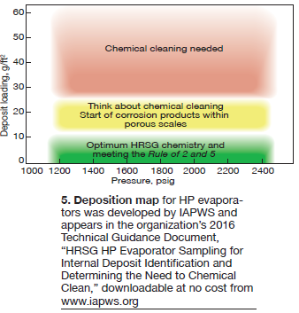
Various rules of thumb also were discussed, including the Rule of 2 and 5, and an IAPWS-generated graphic on deposition in HP evaporators (Fig 5). The Rule of 2 and 5 applies to optimum total iron levels in the condensate/feedwater (<2 ppm) and in the evaporator/steam drum (<5 ppm).
A few conclusions about under-deposit corrosion:
- 1. Visual examination of a tube is generally not sufficient to distinguish between hydrogen damage, caustic gouging, and acid phosphate corrosion.
- 2. Metallography and deposit analysis are necessary to determine the correct mechanism.
- 3. Once the mechanism is identified, a root cause analysis is needed to eliminate future damage.
- 4. Identifying RCCS is key to avoiding UDC mechanisms.
Discovery
Stressing again the need to clearly identify and define the damage mechanisms, Dooley emphasized the need to link visual inspection with plant chemistry. “Include the chemists,” he said. A proper, complete inspection program should also involve someone at the VP Operations level to give it proper weight. “Develop a corporate mandate,” he recommended.
And identify the vulnerable systems:
- Look at all susceptible systems that contain the following:
- Carbon steel.
- Flowing water or wet steam.
- Consider system design and operating features.
- P&IDs, heat-balance diagrams.
- HRSG circuit design and thermal performance.
- Review water chemistry.
- Current and past practices and guidance.
- Parameter analysis compared to IAPWS
- Instrumentation compared to IAPWS
- Document the review.
“Look closely at all the interfacial areas of fluid and materials,” he said.
Bringing it home
Near the end of Day Two, participants were asked some specific technical questions. The questions were designed for thought, for ideas, for discussion, and for analysis. All were verbatim inquiries from operating plant personnel asked of Dooley and his colleagues.
Participants walked through the thought path for each, adding focus and meaning to the two days of discussions.
This was real-world stuff to carry home to real-life jobs. CCJ