


Shop tours, robust discussion highlight 16th annual meeting
Robust presentations and group discussions, and tours of three manufacturing and repair facilities, combined to make the 501D5-D5A Users’ 16th Annual Conference and Vendor Fair a valuable learning experience. A significant portion of the technical exchange between the OEM and owner/operators, and among the two-score users in closed sessions, focused on rotor-related issues—vibration in particular. The 2012 meeting was held in early June at the Charlotte (NC) City Center Marriott.
The steering committee for this group is chaired by Gabe Fleck of Associated Electric Co-op Inc, Springfield, Mo. He is supported by Vice Chairman Barry Mayhew, maintenance manager, Cardinal Power, Ontario, Canada, and Director Lonne Grote, lead O&M technician at Rocky Road Power Plant, East Dundee, Ill.
Although the D5 and D5A fleets are not large, Siemens Energy Inc provides them the same level of technical support it gives to its F-class fleet, judging by the quality of the OEM’s presentations and the first-hand knowledge of the engineering leaders making those presentations.
The first D5 was installed 30 years ago. Today there are 89 units in service, with the fleet leader reporting more than 235,000 operating hours. There are 61 D5As in service, the first achieving commercial status in 1996. The fleet leader has more than 110,000 operating hours. Interestingly, given the relatively low price of gas, the D5s are not running as much as they were a year ago; the D5As are slightly behind last year’s run times.
OEM presentations
Technical topics addressed by the Siemens service engineering team included the following:
Rub distress attributed to a loss of turbine axial clearance has been observed on some R2, R3, and R4 blade platforms. Keep in mind that the turbine cylinder grows faster than the rotor on startup. Rubbing may occur because the vanes, which are attached to the case, move downstream somewhat while the rotor blades hold a fixed position. A root-cause investigation has suggested cutback modifications to increase axial clearances between stationary vanes and rotating blades and these mods have been implemented in a few engines. Field experience is being tracked.
R4 shroud wear has been observed on some D5A turbine blades, particularly those made of U520 material and having significant operating hours. Blade material was changed to IN738 about seven years ago to improve manufacturability. Hard-facing of shroud contact pads may mitigate the problem. Field tests are in progress. Users were urged not to mix U520 and IN738 blades in a given row.
Importance of rotor belly bands in preventing the loss of cooling air from between adjacent turbine wheels was stressed. Keep in mind that reduced cooling air flow to rotor components accelerates component degradation because of higher metal temperatures. If wear/cracking of the original two-piece belly bands is experienced, suggested solution is removal and replacement with a proven three-piece design which can be installed in the field.
Cracks have been observed in the exhaust baffle seals on some units. One concern is the possible recirculation of hot exhaust gas, which could cause overheating of the turbine casing and/or thermal distortion of the exhaust cylinder and some structural elements. Replacement of the seal in-kind requires removal of the exhaust manifold, a time-consuming job. A new seal has been developed, based on F-class experience, which does not require removal of the existing baffle plate for installation. Field testing of the prototype design is in progress.
A vibration improvement program initiated by Siemens to assess issues experienced by some engines in the 501D5-D5A fleet was said to have the OEM’s highest priority. The effort was initiated following the user group’s 2011 meeting and is being guided by a committee that includes both Siemens engineering managers and user representatives.
Independent consultants are assisting Siemens in the evaluation and specialist teams were formed to conduct a root-cause investigation, perform engine testing, model rotor dynamics, evaluate data collected, and make operational recommendations. The comprehensive interim report presented by a half-dozen subject-matter experts at the Charlotte meeting identified promising corrective measures and next steps.
Users unable to attend the conference can access the OEM’s presentations via the Customer Extranet Portal. If you are an owner or operator of a D5 or D5A and not registered to access material on the CEP, and need help navigating the registration process, contact your plant’s Siemens representative. The information you’ll find on the portal is vital to reliable and efficient operation of your engine.
User presentations
User presentations and candid discussion are the lifeblood of user-group meetings. Several owner/operators presented at the Charlotte meeting. Below are a few notes on four of the presentations. Users registered on the group’s website can access these presentations online. If you’re an owner or operator of a D5 or D5A, the registration process is simple; contact gfleck@aeci.org if you experience problems.
Exhaust-bearing vibration spikes caused by coking of lube oil in the bearing. This was a particularly interesting presentation, one perhaps of value to owner/operators of gas turbines other than the D5. The affected engine, a D5 in base-load service (only two or three starts annually), experienced plugging of its bearing cap exhaust line with coked lube oil.
This led to coking in the bearing along the shaft which caused vibration interpreted as a rub. Plant personnel could not clean out the flex line from the bearing cap to the vacuum manifold line on a regular basis because the unit was running all the time. But when they did, using a homemade Roto-Rooter type of device, vibration levels returned to normal.
Identifying the root cause of the vibration issue and correcting it took a great deal of effort over a period of years. The complete story includes (1) replacement of two vibration probes originally located downstream from the bearing cap with four probes on the bearing cap to warn of plugging earlier, (2) replacement of the original flexible vacuum line off the bearing cap with stainless-steel pipe having a smooth internal surface, and (3) addition of a dedicated exhauster to serve the bearing, thereby enabling regular cleaning of the vacuum line to avoid coke formation.
Important to note is that when the vacuum line coked up, oil squeezed by the labyrinth packing and ran along the shaft until it dripped onto the insulation below. Fires resulted—more than a dozen over the years. The speaker said the dry chemical extinguishing medium and oil created a real mess. This scenario apparently is in the past now with the bearing running normally and within spec regarding lube-oil temperature.
Next step for plant personnel is a thorough check of the exhaust frame and associated seals for proper alignment and condition during the upcoming outage. Thought is that the higher-than-desired temperature in the bearing tunnel probably is caused by leakage of exhaust gas into that space.
Closing keys broke off R1 compressor stage and went downstream, causing FOD. Vibration levels offered no indication of the event or resulting damage. The broken keys, attributed to high hours on turning gear, were found by OEM personnel during the investigation of another matter. A 27-day round-the-clock outage was needed to make the necessary repairs.
A R4 turbine-blade failure that caused six adjacent blades to snap off (at about 10% of their respective heights from root) and bring the rotor to a complete stop from full speed within two minutes was announced with a loud bang. Resulting vibration caused the bearing oil line to rupture. The engine’s R4 turbine blades were of the latest generation, installed in 2006. The peaker had 400 starts and only about 2000 hours of service on the blades when the failure occurred.
The owner has not yet completed its accident analysis, but believes the failure might have been caused by a combination of shroud wear (see second bullet above in the section on OEM presentations) and a casting anomaly. Thinking is that blade vibration attributed to shroud wear from high turning-gear hours magnified the anomaly, causing the blade to fail. Corrective action taken includes implementation of intermittent turning-gear operation, hard-facing of shroud contact pads, and the addition of root springs.
Considerable discussion on the need for more rigorous nondestructive examination (NDE) of castings ensued. Some users expressed dissatisfaction with the way rotors are being bladed today and suggested that all blades in a given row should come from one vendor and one casting run. Indication was that most blade rows mix and match among casting suppliers and heats. Another thought was to digital x-ray all castings before proceeding further with manufacturing.
With lunchtime fast approaching, Chairman Fleck squeezed in one more user presentation, that by a user reporting on the performance of OEM turbine vanes upgraded by a third party. No time for details or discussion at this point. The takeaway: Third-party mods—specifically, the addition of cooling holes—offered better performance than vanes with the original cooling configuration.
Discussion among users
User-only discussion sessions can cover a great deal of territory at a well-managed meeting. Here are a few notes from Charlotte:
Strut shields. One user was planning to have new shields fabricated. The originals suffered so much cracking and fatigue over the years, he said, further attempts at weld repair were pointless. High exhaust tunnel temperatures were identified with the D5 but not the D5A. A colleague suggested that tunnel temperatures be maintained below 400F to avoid cracking.
Strut-shield integrity is of concern, the first operator said, because if exhaust gas gets by the shield and attacks the strut, damage can cause a shift in the exhaust casing which conceivably could migrate and encroach on R4 turbine blades. Discussion followed on how best to replace struts. Consensus thinking was “one at a time” and to follow procedures developed by F-class users. Replacing all struts was considered a two- or three-day job.
Weld repair of exhaust-cylinder cracks: Use Inconel 82 wire. Wire matching the material characteristics of the exhaust cylinder material doesn’t work reliably.
Varnish mitigation always is a topic associated with seemingly endless discussion. At the 501D5-D5A meeting that certainly would have been true if the floor leader didn’t limit the exchange. Experience with various types of oils, “proper” testing methods, etc, all were noted. One must ask: Does anyone ever really solve a varnish problem?
Mashing of fins in rotor air coolers was another discussion topic. Replacing bundles of copper/nickel tubes with ones of stainless steel was a solution for one user.
Vibration on engine start received significant air time. Most users participating in the discussion experience vibration levels higher on starts than during normal operation. Numbers above 8 mils were experienced by one user on starts; a couple of attendees thought that too high. Vibration during normal operation was below 3 mils, which colleagues considered normal.
An attendee mentioned that the resonant frequency of bearing pedestals was at 3500 rpm and this could be associated with the high startup vibration. Yet another user said he has two of the same engines side by side and they have dramatically different vibration profiles. Example: One suffers high-vibration episodes when ambient temperature exceeds 100F. Conceivably, most or all vibration issues will be resolved as the OEM’s vibration improvement program moves forward (see last bullet in section on OEM presentations).
Proper greasing of trunnions was stressed: Grease them often, grease them well was the advice.
Proper specifications was another subject introduced. In some cases, the dissatisfaction of contractor performance can be traced to specifications lacking appropriate detail. When this occurs, expectations are not met. Consensus of the group was that specifications should be developed by personnel on the deck plates with expertise in the equipment requiring repair, inspection, upgrade, etc.
Shop tours valuable
You could call 2012 the “Year of the Shop Tour.” Most of the user groups dedicated to gas-turbine owners and operators got out of the classroom for a half day or so to see firsthand what’s going on in the manufacturing centers and repair shops serving the industry. Hundreds of millions of dollars have been invested in expanding and upgrading these facilities over the last several years to satisfy global demand and to transition, to the degree possible, from worker-intensive processes to automated machining centers, high-technology nondestructive examination (NDE), etc.
A visit to a modern manufacturing center dispels the notion that skills lost through worker retirement were going to cripple the industry. To the contrary, retirements may have facilitated the transition to hands-off manufacturing controlled by sophisticated software and machine tools. This is not to say skilled machinists are no longer needed; they most certainly are. However, today you need fewer of them today than in the past.
If you haven’t visited a shop within the last decade or so, it’s almost unnerving to stand on the floor of a modern turbine/generator manufacturing center and watch product flow, with a minimum of human intervention, into special shipping containers to protect against damage. There are relatively few workers in view and the building is quiet, spotless, well lit, air conditioned, with no dust or odors in the air.
Direct involvement of shop personnel on most visits is particularly valuable. Sanitized canned presentations by a tour guide are old school. Today you get to listen, for example, to the coating specialist at his or her workstation on what they do to assure quality of your hot-gas-path (HGP) parts; you have the opportunity to ask technical questions and get the answers you need to make better decisions for your plant and company. Worker pride is clearly in evidence at every tour stop. Not attending a user group meeting with a planned tour is a valuable opportunity lost.
Fleck and his steering-committee colleagues took maximum advantage of the Charlotte location to arrange tours at Siemens, Liburdi, and Pioneer Motor Bearings. The outreach program was very well received by attendees.
Siemens’ new manufacturing facility in a word: Wow! Experienced powerplant personnel are not easily impressed. Then they get the opportunity to visit the new Siemens facility and minds must be recalibrated regarding the capabilities of American manufacturing for the global electric power industry both in terms of quality and quantity. You don’t have to be impressed with the more than one million square feet of shop space under roof, the 100-ft-high manufacturing bays, and the latest automated machine tools and inspection techniques, but if you’re not “show me better,” as the saying goes.
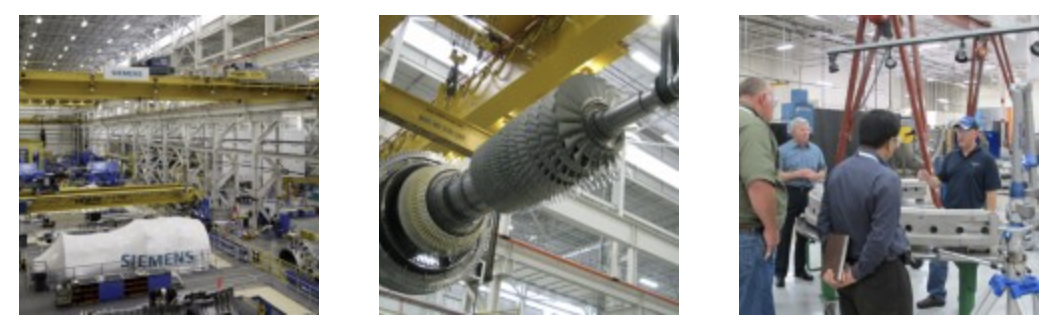 Part of the overall facility is more than 40 years old—Westinghouse Electric Corp built the first 550,000-ft2 shop space in 1969 to make LP turbines for nuclear powerplants—but that has been upgraded and spruced-up. Siemens acquired Westinghouse in 1999 and announced plans to add more than 400,000 ft2 to the Charlotte manufacturing complex in March 2010. The integrated facility hums round the clock every day of the year.The 501D5-D5A visitors were told to keep a sharp eye for ongoing construction in the facility, which will employ more than 1800 upon completion. But there was so much manufacturing in progress it was difficult to believe the mega-shop was not finished. Charlotte has three basic products: gas turbines, steam turbines, and generators (Figs 1 and 2). Capacities offered extend from 150 to more than 1600 MW depending on the machine and its application. The shop also is a center of excellence for mods, upgrades, and major repairs and does some critical parts manufacturing as well (such as gas-turbine transition pieces).
Here are a few of things recalled by the editors following the tour:
•Rotor and compressor component manufacturing incorporates the latest lean-flow principles. There is no reverse flow on the shop floor, distance between work stations is minimal, zero-gravity lifts are used to the extent possible.
•Rotor manufacturing is conducted in an aisle about 200 yards long and adjacent to the rotor service center, which includes incoming inspection. Everything needed to assure success in rotor manufacture and repair is located on the shop floor—including offices, machining, heat treatment, all tooling, NDE, etc.
•At the component level, one skilled employee typically handles the operation of two or more machining centers.
•The generator section of the shop gave the impression of a wartime mobilization unit with perhaps more than two dozen rotors in various stages of manufacture (or repair). There were rotors for 50- and 60-Hz machines with far-off destinations, in some cases, according to workflow paperwork. The tour leader guessed that only about one-third of the generator rotors produced might be for domestic service. Process flow through the generator rotor manufacturing area was continuous and straight ahead like the GT rotor line.
•With such high bays throughout the shop, storage facilities for machine parts, tools, etc, are vertical.
•The GT assembly area was particularly impressive, having the capability to build seven 200-MW-class units simultaneously and ship upwards of one gas turbine a week if necessary. Only 501FD4s were being assembled during the user tour. These engines are distinguished by their relatively short rotors compared to earlier versions of the 501F. Thirteen-stage compressors are the reason. Recall that earlier versions of the 501F compressor had 17 stages. The new machines also have inlet guide vanes on four stages instead of the traditional one.
•Siemens went the extra step to accommodate the D5 and D5A users by putting out on the shop floor various pieces of combustion equipment for “show and tell,” including some cutaways to get a first-hand feel for the hardware that would be discussed in the classroom the following day.
Liburdi operates two businesses from its Mooresville facility that support power producers: turbine services and welding equipment/services. Most of the users on the tour knew Liburdi because of its reputation for quality repairs of HGP parts (see “Optimal tip clearance” in the Frame 6 Report from this issue).
The North Carolina shop specializes in the repair of fuel nozzles, combustion baskets/liners, transitions, nozzles/vanes, blade rings, and shrouds. The visitors observed Liburdi’s in-house capabilities—equipment, procedures, and qualified personnel—for removing coatings, providing state-of-the-art NDE and metallographic techniques, etc (Fig 3). The company’s LPM® (Liburdi Powder Metallurgy) process also was reviewed along with its machining (manual, CNC, and EDM), welding, heat treating, and atmospheric plasma-spray capabilities.
Sister business, Liburdi Dimetrics, makes automated orbital welding equipment for sale or rent. The company offers a wide range of GMAW, GTAW, and hot-wire orbital weld heads and power supplies for precision joining of tubes, piping, and bellows. R, PP, and S stamps enable Liburdi to support training, certification, and welding activities for powerplant maintenance and new construction.
Pioneer Bearing’s plant opened in 1990, specially designed to facilitate the manufacture and repair of large babbitted journal and thrust-bearing assemblies. One cause of bearing damage that plant owner/operators are seeing more frequently today is arcing attributed to stray shaft currents. First step in dealing with such damage is to the repair the bearing; second step is to install a proper shaft grounding system.
Work in progress at Pioneer when the users visited included babbitt being poured. The gas-turbine O&M specialists in attendance knew that the dynamic behavior of rotating machines could change over time but some may not have realized that bearings sometimes can be modified to provide a smooth-running machine, reducing requirements for special maintenance and restricted operations.
A good complement to the shop tour is the presentation Technical Services Manager Fred C Wiesinger Jr made to attendees of the CTOTF’s Combined Cycle Roundtable at the group’s 2012 Spring Turbine Forum in Williamsburg, Va. There was no classroom-style presentation on the care and feeding of fluid-film bearings at the 501D5-D5A Users meeting.
Wiesinger’s presentation, available for viewing by any user registered with the CTOTF Presentations Library (it’s easy to register), covered bearing casting processes, NDE to verify proper bonding of metals, importance of proper lubrication, inspection, damage identification, analysis, and investigation, and several case studies. It is worthwhile reading whether or not you were on the tour. CCJ