Mitigate fatigue cracking in HRSGs
The half-day HRSG Spotlight Session that HRST Inc, Eden Prairie, Minn, has conducted in conjunction with the 7F Users Group meeting for the last several years is designed for plant personnel who want a refresher on heat-recovery steam generators and an update on industry concerns with large triple-pressure units.
Focus of the 2012 workshop was fatigue cracking, with Amy Sieben, PE, presenting on failures in superheater/reheaters and panelized economizers, and Scott Wambeke, PE, addressing drum-nozzle cracking and fatigue in return-bend economizers. Sieben opened the session by saying that fatigue cracking is one of five mechanisms that account for more 90% of all pressure-part failures suffered by HRSGs. The others are flow-accelerated corrosion (FAC), corrosion fatigue, chemical attack/under-deposit corrosion, and dew-point corrosion.
Fatigue cracking occurs, she said, when material is repeatedly stressed beyond its yield point. Low-cycle fatigue is the term used to describe fatigue failures that occur in fewer than 1000 cycles. Sieben introduced an important term into the lexicon of many attendees when she stressed the importance of managing the HRSG’s “fatigue bank account.” Fatigue cracking can initiate on the inside or outside surfaces of pressure parts, the boiler designer continued, noting the three components of fatigue: pressure, temperature, and external piping stress.
Superheaters, reheaters
Tube-to-tube temperature differences cause cracking in superheater and reheater panels for two primary reasons:
- Condensate blockage and poor drain design. Inability to remove condensate in timely fashion during/following a unit purge often is traced to undersize, ganged, or closed drains.
- Water introduced through interstage desuperheaters, which are located between the primary and secondary superheaters and reheaters. Typical causes include leaking spray-water supply valves, hunting, poor piping arrangements, overspray, and a primary/secondary superheater (or reheater) surface arrangement that is incompatible with a given turbine’s performance at startup or low load.


Note that attemperators sometimes are installed downstream of the final superheater or reheater surface in lieu of, or in conjunction with, an interstage desuperheater. Two concerns shared by owner/operators regarding the use of “downstream” attemperators: (1) Additional cost and (2) the risk of steam turbine damage in the event of a failure.
A couple of slides illustrated for first timers the two basic types of desuperheaters used in HRSGs: (1) Probe style with single- or multi-nozzle axial injection and single- or multi-nozzle radial injection. Reported advantages of the latter are that spray nozzles are not in the steam path and steam/water mixing generally is more efficient than with the probe style attemperator (see article, p 98).
Sieben then expanded her coverage of the two bullet points above. She began with a few photos and drawings illustrating how humping of lower headers equipped only with center drains can allow condensate to block tubes at the ends of superheater and reheater panels and cause buckling of those tubes. Having multiple drain locations is one way to solve this problem. Discussion of the dos and don’ts of drain system design came next. Here are the important take-aways:
- Purge condensate from lower headers before every start. Automatic valves are needed to do this effectively.
- Drain condensate as it forms during the gas-turbine purge cycle.
- Proper sizing of drains is critical. Keep in mind that drains too large or too small can be problematic.
- Locate blowdown tanks below header drain locations.
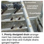
- Avoid combining drains (Fig 1). Be especially careful not to interconnect drains operating at different pressures: The higher pressure drain can block condensate flow from the lower-pressure line.
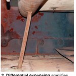
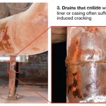
Sieben next noted that a proper drain must allow for a full range of motion between the penetration seal and the access hole in the HRSG casing. Differential expansion amplifies drain lateral displacement, she said, illustrating the point with Fig 2. Drains that collide with the floor liner or casing often suffer stress-induced cracking (Fig 3).
Ineffective draining of cold reheat lines, and occasionally main steam piping, also is conducive to damage. Sieben spoke about water hammer resulting from a slug of condensate being pushed through steam piping during startup. Typically, she said, pipe supports are bent, or thrown out of position; piping may be damaged as well. Tube damage is a possibility, too, if a slug of water reaches the HRSG. Sieben offered a checklist on how to avoid water hammer:
- Drain steam piping before every gas-turbine start. Best practice: Automate valves and install condensate detection for added protection.
- Confirm piping slope and the ability of the drain system to clear condensate from the entire line.
- Prevent the possibility of water accumulation upstream of valves—especially the steam-turbine bypass.
- Tightly control bypass/letdown valve attemperation.
- Check for leaking attemperator spray water.
Before addressing in detail the desuperheater problems identified earlier, Sieben reminded attendees of recent changes to the ASME Boiler & Pressure Vessel Code regarding attemperators. First, drain pots downstream of desuperheaters must be able to detect water automatically and to drain it without operator intervention. Second, superheater and reheater drains must be able to detect and drain condensate both under pressure and at atmospheric pressure.
Leakage by block and control valves usually can be prevented, Sieben added, sometimes by simply specifying Class V shutoff or better. Confirm leak tightness by finding no drop in steam temperature across the desuperheater. Attemperator hunting, most common at low load, causes chronic cycling with the possibility of fatigue damage in the probe, liner, and/or piping. Hunting increases the likelihood of finding water in the superheater.
Attemperator overspray can damage superheaters and reheaters, and, in the case of desuperheaters downstream of those heat-transfer surfaces, may cause catastrophic damage to the steam turbine. Overspray usually is attributed to one or more of the following conditions:
- Poor atomization of spray water because of probe/nozzle damage or partial plugging.
- Improper piping design—in particular an insufficient straight run of pipe upstream and/or downstream of the attemperator.
- An arrangement of superheater and/or reheater surface that allows overspray to occur at some operating points (typically startup or low load) because all the water cannot be evaporated.
Sieben spent several minutes explaining the last point by way of diagrams with actual gas and steam temperatures and spray-water flow rates for varying loads both with and without supplementary firing, and for different ratios of superheater and reheater primary and secondary surface.
One example presented: A superheater for an F-class HRSG designed with 60% primary surface area and 40% secondary surface area requires no spray water when operating at base load without duct burners in service, but needs 43,000 lb/hr of spray water at min load with supplemental firing. For a superheater having 70% of its surface area in the secondary bundle, 55,000 lb/hr of spray water would be required at min load without duct burners.
Correcting for overspray can be extremely challenging and expensive, Sieben continued. Options she offered included these:
- Bypass a portion of the HP saturated steam flowing from the drum to the primary superheater thereby cooling steam exiting the secondary superheater. Same logic can be applied to the reheat circuit, with some of the cold reheat steam being withdrawn ahead of the heat-transfer surface to cool hot reheat. This option is rarely practical because of the expense involved and because reducing steam flow to superheater/reheater panels can increase metal temperatures above recommended limits.
- If too much surface is installed, remove fins and/or gas baffles, or use tube shields, to reduce heat transfer.
- Add a final attemperator or an additional interstage desuperheater.
- Minimize or eliminate the need for spray water on startup by installing an air attemperation system.
Economizers: panelized, return-bend
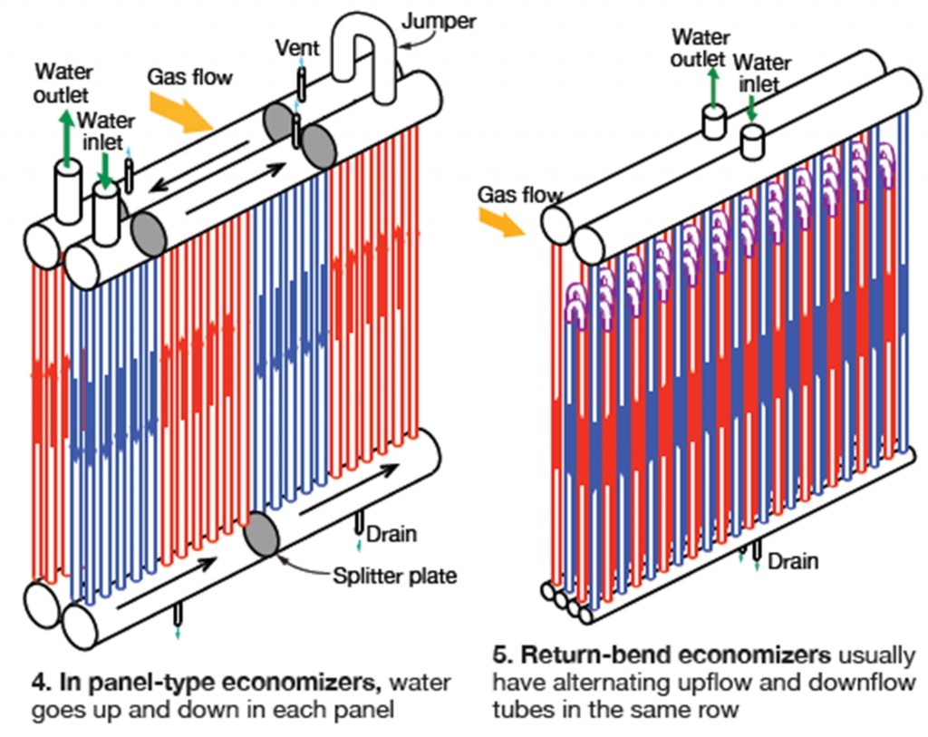
In panel-type economizers, Sieben said, water goes up and down in each panel, or harp, making from two to six passes depending on the number of baffles or splitter plates installed in the upper and lower headers (Fig 4). There are from one to three rows of tubes per panel. Return-bend economizers usually have alternating upflow and downflow tubes in the same row (Fig 5). In some cases, water flows up one row, down the next—a serpentine arrangement. High points in return-bend economizers typically cannot be vented, which can be problematic under certain operating conditions.
Thermal shock. Sieben said that, depending on panel geometry, a temperature differential between tube rows of from 30 to 100 deg F can cause thermal shock, which contributes to fatigue failure. Such a differential can occur in headered-economizer inlet passes, and in the upper bends of return-bend economizers, at top-off or startup. The boiler engineer explained: During startup, operators expect drum level to swell and the feedwater control valve is closed; no water is flowing through the boiler. During this time, economizer panels “soak” to temperatures higher than normal.

When HP drum level finally starts to drop, the feedwater control valve opens and “cold” water “shocks” the economizer (see article, p 74). Recall that economizer tubes have rigid connections at both ends and high tensile stresses result when panels are shocked. Tube leaks often result at tube-to-header welds. Similar or worse shock can occur when adding water to an economizer during overnight shutdowns. Sieben strongly suggested that operators resist the temptation to do so, even if the water level drops to the bottom of the gauge glass. No heat is being added to the HRSG, she said, so this is not a problem.
Sieben then offered the following operational guidelines to minimize the possibility of thermal shock:
- Trickle-feed water through the HP economizer as soon as drum pressure begins to increase.
- Assure positive feedwater flow thoughout the startup period. A small startup control valve may help because the main feedwater control valve installed should not be throttled below its minimum position of 5% to 10% open. A startup valve can be retrofitted in parallel with the main valve to handle low flows.
- Start the main boiler-feed pump when HP drum pressure begins to increase and blow down as needed to control drum level. Important: Do not stop water flow once started; that would initiate another thermal-shock event. Damage from such events is cumulative.
Buoyancy instability. Sieben moved on to two other fatigue mechanisms: buoyancy instability and steaming economizers. In explaining the first phenomenon, she reminded that warm water is less dense than cold and wants to rise, and that most HRSG economizers have a portion of their tubes that flow down.
If the downward velocity is too low, the buoyancy of warm water can cause flow stagnation in down-flow tubes. In extreme cases, flow may actually reverse. Such instability reduces economizer heat transfer, adversely impacting performance. More importantly, tubes experiencing stagnant and reverse flow become hotter than neighboring tubes. The level of stress increases in these tubes, in particular at reduced loads when fluid flow is low. Hundreds of thermal cycles can occur daily, leading to fatigue failures.
Buoyancy is a design issue, Sieben continued, that can result in some tubes being from 30 to 60 deg F hotter than adjacent tubes—not a good situation. Damage caused by buoyancy issues sometimes can be mitigated by modifying the flow circuitry of pressure parts. Adding a recirculation circuit to the economizer is another possible solution.
Increased fluid velocity can overcome buoyancy instability. Rearranging baffle plates in headers may correct the situation, but this could be costly and require significant outage time. Testing and engineering analysis may indicate certain operating loads where buoyancy issues are especially problematic. Perhaps operation at these loads can be avoided, or at least minimized.
Economizers often steam during startup, and when operating at low load without duct burners in service. Steaming can cause vapor lock and flow stagnation. In some cases, the pockets of steam are pushed through a boiler’s fluid circuitry by water flow when the unit reaches full load. Vents can eliminate steam pockets in panelized economizers, Sieben said, but this would require too many manual vent valves. In return-bend economizers, “surging” feedwater flow may clear steaming or buoyancy-instability issues.
If your economizer is steaming at base load, Sieben told the group, one of these three conditions probably exists:
- Design water-outlet temperature is too close to saturation—that is, the approach is too small.
- The economizer bypass is not operating properly or it is under-designed for the service.
- Under-performance of upstream (with respect to gas flow) heat-transfer sections.
Return-bend economizers
Regarding return-bend economizers, Wambeke had these comments on thermal shock:
- Ability to withstand thermal shock well.
- A few plants have reported tube cracking or flattening of return bends at the top of the bundle.
- Maintaining slow flow during startup helps to mitigate vapor locking and reduces the risk of other problems.
Wambeke said buoyancy instability is difficult to correct in this type of economizer. It causes flow stagnation in downflow tubes, which run hotter than upflow tubes. Serpentine return-bend designs are most susceptible to this problem. Steaming in a return bend may create a trapped steam pocket that is very difficult to clear.
ShockMaster® economizer
If economizer issues cannot be managed successfully using any of the solutions mentioned above, Wambeke suggested that owner/operators consider replacing their existing economizers with HRST’s ShockMaster. The defining feature of the ShockMaster is that water flow is upward through all tubes. Water collected in the upper header of one panel flows by way of a downcomer to the lower header of the next harp in the series. Sufficient flexibility is designed into the piping system to accommodate panel-to-panel differential growth—even during startup “thermal shock” conditions.
With upward flow, Wambeke continued, buoyancy forces are in the same direction as fluid flow, which is conducive to uniform flow through all tubes in a given bundle. Because each panel is single-pass, all tubes at nearly the same temperature there is no possibility of buoyancy instability. To date, HRST has done three conversions and provided ShockMasters for four new units. The new product can be incorporated into any manufacturer’s HRSG, the boiler designer said.
Steam-drum nozzles
Wambeke’s presentation on steam-drum nozzle cracking covered much of the same ground as HRST’s Bryan Craig, PE, did at last year’s HRSG Spotlight Session for 7F users. But given industry concerns with nozzle cracking, this year’s presentation provided guidance on what to do if damage is identified and offered lessons learned from two recent experiences. If cracks are found, Wambeke suggested that the following steps, among others, be taken:
- Determine the root cause of the cracking.
- Remove existing defects.
- Confirm complete removal of defects with an appropriate method of nondestructive examination (NDE).
- If remaining thickness after excavation is less than that allowed by the ASME Boiler & Pressure Vessel Code, weld repair is required. Code calculations using actual drum component thickness can quickly determine the need to weld, or not.
- Prepare the entire weld area to bright metal and perform weld prep.
- If the original code of construction requires post-weld heat treatment (PWHT), review the National Board Inspection Code (NBIC) for alternative methods. Wambeke pointed out that for HP drums, the original code of construction likely will require PWHT, which must be done in a band around the drum circumference—typically impractical. It is better to avoid PWHT, he said, than to perform it incorrectly. Alternative methods involve preheat and have restrictions on weld interpass temperatures. Make sure to have an Authorized Inspector onboard with your repair plan before starting work.
- Complete the repair using the shielded metal-arc welding process and inspect as necessary.
Case history #1. Cracking of a downcomer nozzle was found during a routine inspection and excavation revealed a crack depth of ½ in. A long, expensive repair was anticipated by the owner. However, ASME Code calculations by HRST engineers showed the drum shell, nozzle, and welds slightly larger than the original specifications, and the remaining thickness after excavation was greater than the Code minimum. The repair was delayed so proper planning and budgeting could be done.
Case history #2. A substantial number of downcomer cracks was found during a routine inspection, leading inspectors to look at risers; 14 of 16 riser nozzles were affected. Repairs could not be delayed in this case.
Wambeke wrapped up his presentation with a list of takeaways from work done thus far on steam-drum nozzle cracking, a common problem in F-class HRSGs. They included the following:
-
- Driving force is thermal stress caused by startup and shutdown temperature ramps.
- Drum nozzle design is important. Example: Full-penetration nozzle welds are better than partial-penetration welds in cycling service.
- Visual inspection is useful, but not sufficient on its own. You can have cracks and not know it. Surface NDE (dye penetrant, mag particle) is the minimum level of inspection recommended, but volumetric NDE (shear-wave or phased-array ultrasonic testing, radiography) is better still for the additional information it provides.
- Reduce cracking risk by controlling temperature ramp rates, but keep in mind that some details are out of your control.
- Try to find cracks early in their development, before they propagate deep into the weld or drum shell.
- Weld repair, if required, is complex and requires careful planning.
- Inspection is vital if your HP drum wall is thicker than 5 in. and the HRSG has experienced more than 800 starts. Have a repair procedure in place.
- Know the design details of drum nozzles.
- Consider changing weld details before making repairs; there may be substantial benefits. CCJ


