


CONTENTS: Coverage includes highlights of safety forum, F users’ open discussion session , G users’ open discussion session, MHPS presentations, Vendorama.
Maintain your competitive edge: Attend the Savannah meeting
The first major user-group meetings of 2015, the 501F and 501G, are coming up fast. Both conferences will run concurrently from Sunday, February 22 through Thursday, February 26, at the Westin Savannah (Ga) Harbor Golf Resort & Spa. Tack on another day to your trip and tour Mitsubishi Hitachi Power Systems’ manufacturing facilities on Friday.
The two groups will come together for discussions on issues of mutual interest—such as plant safety, vendor fair, supplier presentations (a/k/a vendorama), meals, and social events. About 200 owner/operators are expected to attend the annual event.
Russ Snyder and Steve Bates, who chair the 501F and 501G steering committees (sidebar), respectively, shared conference highlights with the editors and suggested prospective attendees get the latest information first-hand at 501f.users-groups.com and 501g.users-groups.com.
The 501F program will feature special in-depth presentations by Siemens, Mitsubishi Hitachi, and PSM, and evening events sponsored by each; plus, user discussion sessions on the compressor, combustion, and turbine sections of the engine as well as roundtables on casings, rotors, generators, inlet and exhaust sections, etc.
If you have not attended a 501F/501G meeting in the last few years and/or are unfamiliar with the term “vendorama,” it refers to technical presentations by third-party equipment and services providers invited and vetted by the steering committees to assure current content of value to owner/operators.
Multiple tracks of vendor presentations begin after the opening safety session and continue until the afternoon break. Attendees receive a schedule grid onsite. Typically, prepared remarks run 15-20 minutes and Q&A up to about 10 minutes. At least one steering-committee member attends each session to assure a timely start and end to the proceedings.
Steering Committees |
|
| Chairman: Russ Snyder, plant manager, Acadia Power Station, Cleco Power LLC Vice Chairman: Ray Martens, plant manager, Klamath Cogeneration Plant, Iberdrola Renewables LLC Vice Chairman: Ivan Kush, director of technical services,Calpine Corp Rene Villafuerte, plant manager, CCC Saltillo, Falcon Group Carey Frost, 501F program manager, Duke Energy Paul Terry, team leader, RS Cogen LLC, Axiall Corp Martha Leskinen, principal engineer, SRP Paul Tegen, chief CT/I&C engineer, Cogentrix Energy Power Management LLC |
Chairman: Steven Bates, plant manager, Wise County Power Co LLC, GDF Suez Energy Generation NA Inc Scott Wiley, fleet maintenance manager, GDF Suez Energy Generation NA Inc Greg McAuley, VP, Turbine Maintenance Group, Calpine Corp Kevin Robinson, operations manager, Lakeland Electric Dan Jorgensen, maintenance manager, Granite Ridge Energy LLC, Cargill Inc John Wolff, technical support/compliance manager, PPL Ironwood, PPL Generation LLC Mark Winne, plant manager, Millennium Power Plant, Millennium Power Partners LP |
 |
|
Safety
Discussion leader for the joint 501F/501G safety session at the 2014 conference, held in the Westin Mission Hills Resort, Rancho Mirage, Calif, February 16-20, was Ray Martens, plant manager, Klamath Cogeneration Plant, who has handled the assignment for the last several years.
Safety has grown dramatically in importance over the last 10 years as evidenced by the increase in presentation/discussion time allocated to the subject at virtually all user-group meetings and the large number of safety entries received by CCJ for its annual Best Practices Awards program.
The exchange among owner/operators in Rancho Mirage reflected the high degree to which safety is woven into plant culture today. Looking back only six or seven years ago, user discussions were dominated by such mundane topics as proper use of safety harnesses, marking of trip hazards with yellow paint, use of eye and hearing protection, hard-toe shoes, etc.
The discussion orchestrated by Martens reflected a high level of knowledge and experience which could prove valuable to rules-setting organizations and insurers were they to open a dialog with users. Plant personnel pointed to differences between OEMs regarding what they consider safe work practices, offered illustrations where regulations may be misguided, and suggested that getting a passing grade on your safety paperwork from OSHA doesn’t mean your facility is “safe.” The discussion left the editors thinking that in some areas, at least, users may be better grounded in safe work practices than the experts.
Arc-flash. A conclusion drawn from the arc-flash discussion was that much could be—and should be—done to improve the clarity of current standards. A couple of attendees addressed the different interpretations possible, one saying interpretations change depending on whom you hire to do your study.
Another felt OSHA’s biggest concern, based on his experience, was the existence of a professional arc-flash study for his plant. An issue with arc-flash stickers was raised. One attendee thought stickers were misleading because they apply to a door-open condition and no one should be opening electrical cabinets when equipment is in service.
Package fire protection and tests to assure leak tightness elicited significant discussion. Questions raised by attendees included the following:
- Should fire protection be operational when flowing gas? One user said the OEM requires a lock-out of fire protection during maintenance when a gas leak is possible.
- What happens if gas ignites during testing?
- Is a fire more dangerous to personnel than FM200 or CO2?
Comments and questions surrounded topics such as fan test, sealing of doors, CO2 dump test, false discharges, effective lifetime of fire-protection systems, most effective suppression/extinguishing medium, etc. At least one user suggested the obsolescence of the fire protection system was becoming an issue at his plant, mentioning that FM200 is not endorsed by at least some insurers. Listening to the rapid-fire questions and comments leads one to believe that an hour session of package fire protection—complete with expert presentations and discussion might also benefit users.
DC lube-oil pump. There were several questions involving this emergency device. One user questioned if overcurrent protection is appropriate. He said insurance companies want the plant to disable the overload trip so the pump continues running, to failure if need be. Is the risk of a motor fire igniting lube a greater risk than the risk of damage/fire to the turbine/generator? Why not have an alarm to warn of a high-temperature condition but not trip the pump. Another session on this subject, including insurers, could provide owner/operators valuable guidance.
Ladders. Plant designers and specifiers might benefit from plant visits and interviews with station personnel. One user reported the injury of a co-worker because the ladder was too close to a structural component and the person lost his footing. A follow-up inspection revealed that only one of more than 40 ladders met OSHA specifications.
Cooling towers. An attendee described an ice-over condition at his plant’s cooling towers and how staff protected personnel while battling Mother Nature. It’s dangerous to have users inspect towers affected by icing. You also don’t want to reverse the fans, this owner/operator of an eight-cell wet tower said, because you can damage the gears.
He recommended shutting off the fans to raise back pressure and melt the ice. You lose some megawatts, he continued (heat-rate loss is about 100 Btu), but roving operators are not put at risk and the tower is not damaged. The user said his plant’s operators shut off each cell in turn, for an hour or so, as temperature drops.
Staff versus contractor personnel. Cost pressures are forcing more plants to use permanent staff instead of field services for some engine work, a user commented. Another said that’s what his plant does for its 501D5A. But when work goes beyond, say, fuel nozzles, and involves baskets, for example, they typically use millwrights for safety and experience reasons.
An interested attendee asked about the plant’s “comfort level” regarding the use of permanent staff in such situations. It becomes a question of time, he was told. Example: A basket had to be pulled by staff during a forced outage because it would have taken the OEM 24 hours to get onsite. Follow-up questions concerned confined space (permit required, or not?) and special tooling.
At this site, confined space is an issue only before the top shell is pulled off the combustor case; after that, it’s just an uncomfortable location. Interestingly, the competing OEMs have different opinions: One calls it a confined space even with the top off and requires all the related paperwork; the other does not. A warning from another user: If you don’t have the personnel with rigging ability to handle components such as top hats, don’t tackle the job.
Finally, someone suggested renting a pertinent tool box from the OEM if you want to do certain tasks—such as top-hat removal—with plant personnel. He said the rental cost for the specialized tooling is well worth the investment. This was an open forum with no formal presentations.
F users
The user-only open discussion session conducted during the 2014 annual conference was organized by engine section—beginning with the air inlet house and compressor. Discussion leaders all were members of the steering committee, chaired by Russ Snyder, plant manager of Cleco Power LLC’s Arcadia Power Station.
Inlet air house. Ice blasting was recommended by several users for cleaning of the inlet bellmouth area and for rotor prep prior to coating of compressor blades. Offline compressor washes in cold climates (below 62F according to a user who said he was quoting the OEM) should be done using a water/glycol mixture.
Another attendee, who reported washing offline every six weeks (no online washes are done), said it’s difficult to control the percentage of glycol in the mixture. Yet another user said, “no problem”; he mixes glycol and water in a tote to the exact formulation required.
Inlet heating is good for allowing wintertime washing, someone added. However, he said that the motivation for adding inlet heating capability at his plant was for achieving low-load turndown within emissions limits, not compressor washing. No owner/operator in the room reported using HEPA filters on 501F engines as a means for eliminating washing.
Water intrusion into inlet ductwork was the next discussion topic. An attendee said icicles form from water droplets in winter where sections of the ductwork are not properly sealed. Easy to find leaks by going into an unlit inlet house in daytime and looking for sunlight streaming through “holidays.” An alternative is to deluge the ductwork with a fire hose and look for water entering the inlet system. A related issue: Water accumulation at the inlet scroll can be problematic when drainage in that area is poor.
One user with a fogging system for evaporative cooling reported poor control of water droplet size and resulting compressor damage. This plant is weighing conversion to a conventional evap cooler. Replacement of incandescent bulbs with LED lighting was being considered by one user for his air inlet house. No one in the group said they had done this yet. However, one user reported that his plant had been running with LED lighting in the turbine package for a year.
Exhaust. A user reported having 8000 hours of service on an advanced two-piece exhaust cylinder and being relatively satisfied with its performance on his base-load unit. However, the install was a challenging experience, he continued, because of the “disconnect” between the field installation leaders and engineering.
Fire protection in the exhaust tunnel was a lively discussion topic. A dry-chemical discharge was considered a cleanup mess users didn’t need. Attendees appeared favorable toward use of CO2. An attendee said he replaced FM200 with CO2 because of the former’s unreliability.
Compressor. Wintertime challenges associated with air inlet houses carried through to the compressor. Discussion opened on monitoring of icing conditions—in particular when operating at low load for extended periods during cold weather. Cameras, infrared technology, and RTDs were incorporated into the conversation.
Best practices for inlet filter/evap media pressure drop measurement and monitoring were next. One user measures delta p across the entire inlet system and brings the info back into the DCS so data can be trended and alarmed.
Replacement interval for evap media was brought to the floor. One user did it for the first time in 13 years, noting that water quality is a consideration. City and demin water are mixed at his plant. Another user relies on guidance from the evap-media manufacturer on water treatment by way of periodic sampling and analysis. Addition of vinegar to the basin and recirculation of basin water when the unit is out of service was suggested.
Most users prefer the bleed-and-feed treatment option based on chloride concentration: Run for a while and dump the sump. One user blows down on conductivity and uses brine concentrator distillate as make up. Question to the group: Has anyone changed out evap media; if so, can you share the experience? One reply: Not voluntarily, the fire did it for us. No dialog ensued.
There was a short discussion on having a mix of parts from OEM, Mitsubishi, and/or third-party supplier in the same unit. The users who have such “mongrel” compressors did not identify any problems associated with the mixtures of parts. One attendee said that his compressor had one vendor’s parts through Row 8, another’s for the remaining stages.
Another short discussion followed on hook-fit repairs. It acknowledged that skilled craftsmen are required, repairs take a long time to complete, and they are expensive. A user reported good experience and reliable operation by inspecting and restoring hook-fits annually.
Combustion section. A user began this portion of the program looking for advice on oil storage and firing. He said his plant hadn’t burned oil in years—perhaps 10, except to verify liquid-fuel capability—and the fuel had degraded. Failed starts attributed to poor oil quality have contributed to fouling of the SCR. After two failed starts the plant would have to burn gas to prevent oil buildup on the catalyst, which could present big problems.
When the plant does run on oil today it starts on gas, switches to oil, and then returns to gas on the way down. To avoid degradation in storage, plant investigated allowing an oil supplier and other oil users to draw from their tank and refill with fresh oil. Too many hurdles in that plan, the group was told.
Extended-interval hardware got some air time. Group was asked if anyone with 12K hardware had migrated to 16K. One respondent said “yes,” adding that his units routinely run 10% beyond that. Another with 8K hardware said that relatively low limit had been stretched to 12K. No response from a question on whether 25K parts allow plant owners to skip a combustion inspection (CI) and go directly to a hot-gas-path (HGP) inspection.
The discussion leader asked if single-layer insulation was providing the heat retention promised. He also wanted to know if it was holding up better than the old style of insulation and if it truly was easier and faster to remove, thereby reducing outage duration. A colleague replied that single-layer insulation comes off and goes on faster than the alternative, but that the saving was measured in hours. The real saving is in not having to do man-days worth of repairs. Users were reminded that fall protection is required for insulation removal in F-class engines.
Mention was made of a gas explosion caused by poor bolting, poor gasket practices, and poor installation. You must use spec bolts, not a mixed bag of fasteners, the group was told, and plant personnel must supervise the makeup of pipe joints. Spectronics Corp was a company identified as one with products capable of pinpointing gas leaks. The speaker said he was looking for a leak at a flange and Spectroline® found the leak in a flex line.
A user reported pretty serious panel cracking in transition pieces that he believes was the result of poor shop work—in particular, work related to cutting off of the picture frame and rewelding it onto the repaired TP. Turns out these were old TPs, dating back to the millennium; they had been repaired and put on a storeroom shelf for reuse.
A colleague enlightened the group: TPs of that vintage had their share of problems, he said. Mechanical stripping and other aspects of the repair process thinned the TPs and cracking was relatively predictable after the picture frames were welded back into place. The user looking for advice regarding his cracked TPs said he needed to get a reluctant management to buy into the need for new TPs and asked for suggestions on what information to pass up the chain of command. Someone suggested telling executives the facts of life: It would cost an unbudgeted $15 million were a TP to come apart and go downstream.
Hot-gas section. R2 trailing-edge cracking issues were reviewed. Next issue: Temperature excursions in disc cavity 4 during startup. A user reported temperature excursions on both cold and hot starts. Temperature would spike and then settle down; it could hit 900F and drop to 600F. The phenomenon was believed related to a damaged interstage air seal that had been “re-machined” by the GT.
Another user reported erratic disc-cavity temperatures: Fine one day, down by 80 deg F for the next couple of days, followed by a return to “normal.” Plant personnel had no clue as to the cause of this behavior.
By show of hands, attendees said they were borescoping twice annually. Everyone was urged to develop a good specification for a borescope inspection.
A user reported the liberation, from a base-load 501FC, of an R3 turbine blade that had been repaired twice by the OEM. High-cycle fatigue is believed the cause, but a root-cause analysis was in progress at the time of the meeting. Finally, an attendee reported a couple of successful 501F service runs with a mixed bag of PSM first-stage blades, Mitsubishi second-stage blades, and PSM transition pieces.
Rotor and casings. Users were urged by a colleague to consider high-speed balance during a shop visit, because it can show you things that are “hidden from view” during a low-speed balance. A general feeling among the users was that the OEM is still learning about how to conduct rotor inspections, develop best practices, know where to look for what, etc. One asked others in the room about their experiences with the OEM’s rotor inspection/repair work in Charlotte—specifically interaction with customers, sharing of information, access and quality of documentation?
Next question: How does the foregoing compare to experience at non-OEM facilities. Sharing of information is major issue in the user community. Limited access to shop facilities and OEM personnel are a sticking point, as are poor documentation and poor photo coverage. Given the tenor of the discussion, one could assume the more collaborative service providers would have greatest market success.
Belly bands were a discussion point, followed by leaks at four-way joints. Regarding the latter, it would seem that Rube Goldberg is alive and well. About 25% of the group had some technique, goop, or whatever to stop the leaks. One user reported having his machine apart eight times with no leakage; the ninth time there was a “ridiculous” amount of leakage.
Generators. Predictable discussions were conducted around spark erosion, partial discharge, retaining-ring inspection, bump test on endwindings, etc.
The auxiliaries discussion focused on dc lube-oil pump testing procedures.
G users
The 501G Users Group is small by industry standards: only 24 engines at a dozen sites in the US and one in Mexico. But the organization’s size, capable leadership, and collaborative nature allow it to think and act as a unit—a SWAT team of sorts—facilitating problem-solving at the deck-plates level and with the OEM.
There’s not much turnover in the top positions at G facilities, at least compared to the industry at large, which means most attendees are familiar with the other participants and their plants. This makes for presentation efficiency and minimal repetition conference to conference. In effect, each meeting (there are two annually) picks up where the previous one ended.
While most other independent groups serving gas-turbine owner/operators organize their technical programs by sections of the engine—for example, compressor, combustion section, turbine, generator, etc—the G users begin with an “annual report” from each plant and follow that half-day program with user presentations on emerging and significant plant-wide issues of importance to the fleet.
Plant annual reports
Highlights of several plant reports presented during the 2014 conference are presented below. The issues identified by the users often were not related to the engine but were the same types of problems faced by other industry colleagues operating combined cycles.
Plant 1. In the last year, this facility completed a controls upgrade which introduced many new and disruptive alarms; plant, the 501G Users Group, and OEM are working collaboratively to rethink alarm philosophy. Low-load turndown capability also was installed, with the expectation of being able to operate at, or below, 50% of rated output. However, a vibration issue has made that an elusive goal thus far.
The plant recently transitioned from base-load to winter peaking service, and, as a result, suffered freeze issues and several unit trips this past winter. Personnel think wind screens and heat tracing can help mitigate the cold-weather effects. Finally, plant output was restricted by SCR fouling.
Plant 2. Turning gears were replaced on two steam turbines at a plant with multiple 1 × 1 combined cycles. One of the steamers also experienced vibration issues: On rolling up to operating speed the unit tripped multiple times on high vibration. The fire protection system experienced ground faults. Conduit was moved to a more favorable environment. Flashbacks occurred in one can of one gas turbine after an outage to install 12,000-hr hardware.
Plant 3 had T3000 integration issues. Engineers experienced difficulty tuning bypass valves to coordinate with cooling of transition pieces on a gas turbine and startup pressure control on the steam turbine. Exhaust temperature on one GT is still operating at 12 deg F under the recommended limit, to prevent flashbacks. A sister unit is operating at design exhaust temperature; however, both engines are producing the same amount of power.
Plant 4 conducted three generator medium inspections in the last year. A short was found in one unit and a field repair was made; outage was extended by 20 days to complete the unplanned work. A T3000 controls upgrade also was done and that project went well.
Plant 5 did a significant amount of work in the last year: a combustion dynamics monitoring system (CDMS) and 12,000-hr combustion hardware were installed on the gas turbine at the 1 × 1 facility, along with the OEM’s thermal performance package, and new belly bands and blade rings. The HRSG tube bundles were cleaned and three LP economizer valves were replaced.
Problems experienced on return to service: plugging of witch-hat strainers, which caused high blade-path differential temperatures; leakage around the HP drum door; high gas-turbine backpressure attributed to misaligned baffle plates in the HRSG. Plugging of the witch-hat strainers was caused by fine particulates released during maintenance activities on the 7-mile gas line serving the plant.
Another user offered that liberated insulation plugged the SCR at his plant, causing a 5% reduction in output. He believed it might be necessary to disassemble the catalyst stack to effectively clean the unit.
Plant 6 did an R2 upgrade to one GT with the latest parts available, and installed new SCR catalyst to increase output. A CI was conducted on the second GT and its HGP was modified because of a parts issue identified during a borescope inspection. Control system was replaced with Ovation™ and a fiberoptic monitoring system was added on the generators.
Plant 7 was forced into a HGP inspection last September because of high R3 disc-cavity temperature. Cause was identified as rubbing between stationary and rotating parts; a root-cause analysis investigation is underway. Vane deflection is the likely culprit according to one plant employee. Blade ring only had 7600 hours of operating time.
Plant 8 suffered flashback events that caused two forced outages. Immediate fix was to dial-back on GT output by 7 MW. Plant also suffered cracking of inlet struts, vibration in exhaust bearing, disc-cavity thermocouple failures, loss of t/c signal from exhaust bearing. Other problem areas: Disbonding of stellite from seats of main and reheat valves; excessive maintenance on fuel-gas control valve.
Plant 9 reported a 3.4 EFOR (equivalent forced-outage rate) for 2013. Belly bands were pushed beyond the recommended 16,000 operating hours, to 24,000 hours, to align with the HGP schedule. There was no indication of problems when they were removed. Replaced bent tabs with U-clip design. New spin-cool procedure was validated; it took about four hours off shutdown time. Now, unit is placed on turning gear for six hours after shutdown; then spin-cooled continuously until disc-cavity temperatures go below 150F.
Other tasks during the HGP inspection included installation of Rev 9 logic in T3K, steam-turbine valve overhaul, and HRSG cleaning which removed 1200 lb of rust. There was a QC issue on R4 hardware replacement: Some platforms were longer than others and the entire row was replaced. Low-frequency dynamics were experienced at low temperatures (below freezing), so the plant installed an updated CDMS.
IGV unison ring was replaced, too. During the previous outage, several rollers were replaced but binding occurred because the new rollers were too tight for the old unison ring. Inlet filters were replaced because of high delta p. Conical pairs were switched from MERV 13 to MERV 16 nanofiber to shed water. Expectation is the new filters will have a service life of at least three years.
Igniter sticking was another issue. Plant experienced high stack temperatures after outages and it would take months to return to normal. Installed vent valves to force more air from the economizer during initial fill post outage to correct the problem.
Reheat steam valve stem was replaced in 2010 with non-OEM parts and again in 2013. Disc spring washers for the valve were incorrect parts. Governor valve had a piston rod with an elongated, out-of-round hole. An HP attemperator nozzle had liberated and was never found. Remaining washers were tack-welded to prevent the back-out of other nozzles.
Report card: The foregoing work on this 1 × 1 combined cycle reduced its heat rate to 6700 Btu/kWh and pushed the maximum output to 102% of nameplate rating.
Hot topics
Repair of exhaust-system components is a relatively common item on outage “to do” lists compiled by owners of Siemens engines, at least judging by discussion time at user-group meetings. A 501G user reported on inspection of exhaust struts for cracking at two plants. No problems to report at one facility but several cracks at the other.
Experience guided the user to grind out the cracks and reweld using a Hastelloy X backing bar about 1 in. wide by 1/16 in. thick. A few months later the repair was still in place. Had the crack been welded without the backing bar, the user said, it would have reopened in about 30 days. A few cracks were marked to show their progression over time and repaired during the following outage.
GT thrust bearing experienced problems which were attributed to low-load vibration. There are two units at this site, one had thrust-bearing issues, the other did not. The speaker said that it’s difficult to reset clearances if have to remove a bearing during maintenance. The unit that was running normally had not had its thrust bearing removed.
ST control-valve stem failure. Steam leakage from the valve stem first thought to be plugged leak-off lines to the gland seal exhauster and cold-reheat system; not the case. Wound up hiring three contractors all of whom were confident they knew exactly what was wrong; not one did. One contractor damaged the valve. Backseat effectiveness questioned.
Most likely scenario was that the actuator was over-traveling and not able to accommodate thermal expansion. More specifically, as the actuator expanded, the valve stem was forced down off of the backseat, subjecting leak-off lines to more than design flow. This was considered plausible. An engineering solution offered by the OEM was to place a 60-mil shim between the actuator and valve body, thereby creating a dashpot and allowing for thermal growth. To be continued.
Plant also has a turning-gear problem: It drops off engagement soon after it begins operating. Investigation continues with the likely suspects being worn bushings, misalignment of turning-gear shafts, and/or insufficient internal oil flow.
Outage actions from around the fleet included the following: (1) A user reported that site observation cards were reviewed with contractors daily; once the contractors knew someone was watching, they did a better job. (2) Proper balancing of a generator rotor required resizing of the collector-end bearing. (3) Catalyst cleaning decreased pressure drop from 3.5 to 2.8 in. H2O.
FAC issues in LP evaporator of three-drum HRSG. Original LP evaporator tubes were made of carbon steel with a 0.105-in. wall. UT inspection of wall thickness in 2010, about 10 years after the unit was built, revealed walls typically were down to 0.8 in. Plan was to recheck in 2014, but a few weeks before the 501G annual meeting a couple of LP evap tubes sprang leaks and a wall-thickness survey revealed a significant number of tubes were below the 0.62 in. minimum recommended by the boiler OEM.
Plant staff was surprised at how quickly the tube material deteriorated once FAC started. A contributing factor might be the change in operating profile from base-load to cycling. Repairs likely will involve replacing headers with ones having stubs welded in place and then field-welding straight tubes between stubs. Interestingly, the HRSG manufacturer switched to P11 tubes several years ago to prevent FAC.
Interstage seal failure. Unit performance degraded quickly after implementing the performance improvement package in spring 2012. There was rubbing of R3 vanes against R4 blades. A drawing review suggested there probably was contact on the R4 disc and the unit was removed from service for an unplanned HGP inspection after 8000 hours of operation. Everything looked good until technicians got to the R3 interstage seal and found a deep groove from the 10 to 4 o’clock positions. Machine was returned to service with new blades, vanes, and interstage seal.
Full HGP, generator inspection. All refurbished blade rings were beyond maximum out-of-round specs and were replaced with new. R2 blades were in good condition and had 6K remaining life; they were installed in the sister unit at the site. Only three R1 vanes had coating and/or oxidation issues that precluded further operation. Six R1 vanes were reinstalled in the sister unit. Combustion hardware was replaced with 12K components. Original U-clip belly band showed no signs of distress. No compressor issues were identified via borescope inspection.
Two generators at the site failed in service during their second year of operation. Parallel ring connection issue was identified and corrected via a rewind. Repairs raised new concern with end-basket resonant frequency; fiberoptic vibration monitor installed. Visual inspections revealed loose end baskets and bump tests were planned. Depending on results, the fields might be pulled and the end baskets stiffened.
MHPS
Presentations by engineers from Mitsubishi Hitachi Power Systems focused on 501F models through the F3. Recall that Mitsubishi and Westinghouse were technology partners in the development of the 501F engine prior to Siemens acquisition of Westinghouse in August 1998. Siemens’ most recent 501F engines, the F4 and F5, are of a significantly different design.
Bill Ray, who heads up sales and marketing for MHPS, provided opening comments and introduced Scott Cloyd, director of gas turbine service engineering, who did the heavy lifting on engine enhancements before relinquishing the podium to Bob McGinty, the company’s business leader for its SCR product line.
Cloyd, widely respected by owner/operators of 501F engines and under considerable time pressure, began at the compressor, moved quickly through the highlights of turbine first- and second-stage components, discussed rotor upgrade offerings, and presented design details on his company’s state-of-the-art two-piece exhaust cylinder which has been modified to serve in engines of Westinghouse design through the 501FD3. Here are the highlights of what Cloyd had to say:
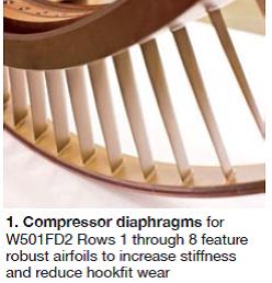 Compressor diaphragms for Rows 1 through 8 feature thicker airfoils than those used by the OEM, thereby increasing component stiffness to mitigate the hookfit wear issue typically identified with the W501FD2 (Fig 1). Cloyd also said the assembled style of diaphragm construction used by MHPSA—that is, the use of mechanical fasteners—is more effective in damping vibration than an all-welded design.
Fleet leader among the FD2s has Mitsubishi diaphragms that were installed in R1, R2, and R3 in 2008. These components now have operated more than 46,000 hours and are said to have experienced more than 500 starts problem-free. They are designed to meet or exceed the OEM’s repair and life intervals. In sum, the assembled diaphragm has more than 2-million hours of operating time across the Siemens and Mitsubishi fleets.
Keep in mind that the M501F3 competes with the W501FD2 and many parts are interchangeable. Example: The FD2 casing accepts Mitsubishi diaphragms without modification. Cloyd told the audience that Mitsubishi purchased an FD2 on the grey market a few years ago, one of its functions being to verify fit-up of replacement parts.
After a brief overview of updated components for the combustion section—including a pilot nozzle protected by a relatively thick layer of TBC (thermal barrier coating) and a liquid fuel system that eliminates the need for a fuel divider—the engineering director discussed the Mitsubishi advantage concerning R1 and R2 turbine blades.
First-stage turbine blade. Cloyd attributed the long lives of Mitsubishi’s R1 turbine blades to a forgiving design and advanced cooling, coatings, and materials developed for the J engine (2912F turbine inlet temperature) that have been adopted by its G- and F-class gas turbines. These included new designs for cooling holes (not simply round holes), thick coatings, modified cooling scheme, redesigned platform area with more cooling, optimal wall thickness (thinner walls on blades in peaking/cycling service), etc.
Fig 2 illustrates a problem inherent in the original R1 turbine blades used on both Westinghouse and Mitsubishi 501F machines, which were designed with a squeeler tip around the full perimeter of the blade. Note at the left how hot gas tumbles over the squeeler creating eddies conducive to tip cracking and oxidation.
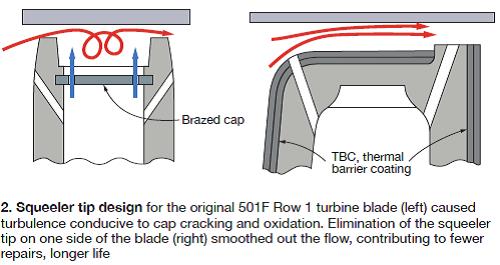
The M501F3 R1 blade design, offered for the FD2 and some other Westinghouse models, has a squeeler only on one side of the airfoil and the hot gas flows smoothly across the blade tip (right-hand sketch). Note, too, that the height of the squeeler that remains is less than that for the original blade.
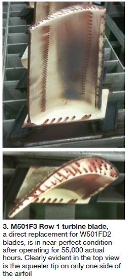 Cloyd was particularly upbeat about Mitsubishi’s successful redesign of the R1 blade, which is cast from the company’s nickel-based MGA 1400DS (directionally solidified) material. Fig 3 shows one of these blades after 55,000 actual operating hours. The row of 72 was sent for a scheduled shop visit; only one blade was scrapped.
The speaker brought one of the blades for the group to see; it looked at least as good on a display table as in the photo. Cloyd said had no doubts that this set of R1 blades would complete three intervals and suggested to attendees that they consider life-cycle cost when comparing bids for replacement parts.
Second-stage turbine blade. Readers may recall several incidents of trailing-edge cracking (just above the platform) in second-stage 501FD2 turbine blades during the second half of 2010. This was a hot topic for several months, but quick response by the OEM, Mitsubishi, and others minimized the impact on the fleet. Cloyd reviewed the details of Mitsubishi’s solution, made available to M501F3 owner/operators in 2004, a full six years before the cracking problem surfaced in the FD2 fleet.
Mitsubishi changed the original R2 blade design developed in collaboration with Westinghouse to one with an optimized cooling circuit, thereby achieving a more-uniform temperature profile across the blade and reducing trailing-edge thermal stresses. A generous undercut, a change in material from IN 738 to MGA 1400, refined trailing-edge grain size, and increased fillet radius and trailing-edge thickness combined to reduce trailing-edge stress by 40% and provide more tolerance for manufacturing deviations.
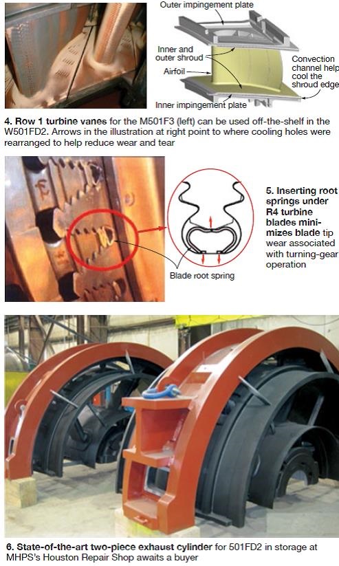
Turbine vanes for Rows 1, 2, and 3, the next discussion point, are made of MGA 2400, which has 100 times the creep strength at operating temperature as the original X45 material. Improvements in cooling with less air flow are highlighted in Fig 4. Service experience with the upgraded vanes points to a reduction in cracking, TBC loss, and shroud oxidation. These benefits reduce repair scope and cost.
Rotors got a few minutes of air time. Cloyd recommended a comprehensive rotor inspection at the second major or 12 years and urged attendees to put added emphasis on tracking trends in critical variables after the first major to guide the planning and conduct of the inspection. Mitsubishi can perform these inspections at its Houston and Savannah facilities. Next, he discussed the spindle-bolt issue identified with two FD2 compressors and the Mitsubishi solution, which can be incorporated into existing units.
Cloyd closed out the rotor portion of his remarks with details on the following:
- An upgraded air baffle (belly band) offering for W501F machines based on Mitsubishi’s design for its M501F, G, and J engines. Belly bands are prone to cracking and wear and should be replaced during hot-gas-path inspections. Features cited by Cloyd included a double-ply light structure and upgraded locking piece.
- The use of springs inserted in the gap between the R4 blade root and turbine disc (Fig 5) is a proven method for preventing blade rock and resultant blade-tip wear and rotor vibration.
The final item in the presentation essentially was an announcement: Mitsubishi has developed a two-piece exhaust cylinder for the FD2 based on the success of its M501F3 design (Fig 6). Serial No. 1 is stored in the company’s Houston repair shop awaiting a purchase order.
Vendorama
The 501F and 501G Users Groups integrate more suppliers into their formal presentation program than any other user organization serving gas-turbine owner/operators. When the steering committees first encouraged widespread vendor participation in 2011, one could not have predicted the high degree of success the Vendorama segment of the annual meeting would achieve virtually overnight. Users do want to hear from vendors about their technologies, but they want to have a choice in what to listen to; Vendorama provides that flexibility.
On Day One of the 2014 meeting there were 42 vendor presentations—six conducted in parallel in each of seven time slots. Below are short content summaries of several presentations selected by the editors for this overview.
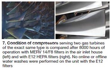
AAF International. Bill Hale provided attendees sufficient information to help them communicate to their management the value proposition for HEPA filters. He began with a review of AAF’s long history in filtration and more than 15 years of HEPA experience and then offered the following technical benefits of cleaner gas-turbine inlet air:
- Greater machine availability and reliability.
- High initial power output is maintained.
- Increased fuel efficiency.
- Longer hot-end component life.
- Eliminates the need for water washing (Fig 7).
- Reduces emissions.
The commercial upside offered by improved performance:
- Increased plant revenue.
- Higher power production.
- Reduced fuel use and, therefore, cost.
- Decreased emissions.
Hale’s slides contained tables and charts with information supporting the points made above, including pressure-drop data for different filtration schemes. He presented scenarios for a hybrid upgrade for an existing filter house as well as a complete retrofit filter house with three-stage static filtration. Regarding the latter, removal of salt is assured to eliminate the possibility of hot-gas-path corrosion.
 Allied Power Group was one of at least six companies presenting at the conference on compressor diaphragms—repairs, design features, upgrades, etc. Alan Lovelace, PE, began with a historical review of diaphragm designs and manufacturing processes, and moved quickly into guidelines for repairs.
He then addressed the blending of minor indications at the edges of the diaphragm airfoils, which Lovelace said, should be done using the 8:1 ratio rule. This means the length of the blended surface along the edge of the airfoil should be eight times the width of the airfoil at the bottom of the defect.
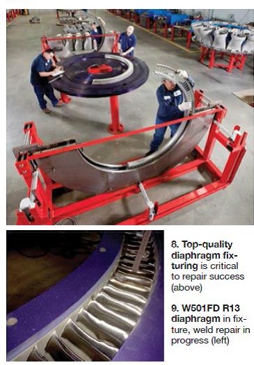
For minor/medium indications, he continued, it is possible to use Inconel 82 weld wire for repairs; no heat treatment is required (Fig 8). But Lovelace cautioned that it is not recommended for any W501FD diaphragms because the airfoils are of marginal thickness by design. Major indications require Type 410 stainless steel weld wire for repairs, with stress relief (Fig 9). The repair expert strongly recommended inspection and dimensional restoration of anti-rotation lands at each repair.
Lovelace commented on possible mods and upgrades—such as replacing labyrinth-style seals with honeycomb seals—before closing with the following remarks:
- The majority of diaphragm repairs are in the minor and medium categories.
- W501F compressors typically have an operating lifetime of more than 80,000 hours.
- The W501FD suffers from harmonics issues, which are conducive to hookfit wear, especially in Rows 1-3. Diaphragms for these engines manufactured before 2000 using the laser welding process should be inspected thoroughly and regularly, Rows 1-3 in particular. Concentrate on inner and outer shroud tenon welds, Lovelace said: Make a good visual inspection, tap test, red dye check if possible.
- Pick your repair facility based on its tooling capability and people. Look for robust tooling/fixtures and experienced personnel.
- Finally, always compare the incoming versus the outgoing dimensions. If there is a big difference, take steps to ensure the parts will fit back into your gas turbine.
Emerson Process Management. Dave Cicconi, a familiar face at user group meetings, covered a considerable amount of material in the half hour he had at the podium, integrating it into a coherent presentation that focused on the following requirements for a successful gas-turbine controls retrofit:
- Vendor prequalification: proven hardware and experienced supplier.
- Definition of scope, including system improvements beneficial to the bottom line and safety—such as conversion from mechanical to electronic overspeed trip protection.
- Application-specific design.
- Well-defined engineering deliverables.
- Customer participation in design reviews.
- Complete testing, including dynamic simulation.
- Detailed outage planning.
- Long-term support.
Cicconi’s slides, available here, contained useful checklists for planning purposes—such as what turbine control features you should consider including in your new system, considerations for vendor pre-selection, vibration monitoring and protection, project drivers for excitation replacement, etc. In closing, Cicconi pointed users to case histories of the company’s controls experience in generating facilities powered by gas turbines available via the CCJ Online Buyers Guide.
JASC. Schuyler McElrath, known by many users for the successful JASC liquid-fuel-system valve solutions he has implemented at their plants, was at the front of the room for another Vendorama presentation. Except this year the subject was not valves, but rather high-temperature metal-to-metal seals; more specifically, copper crush gaskets. They were developed by JASC back in 1996 to provide zero leakage between and fuel and purge-air housings of its three-way purge valve.
With technology borrowed from the 3WPV crush seal, JASC is developing a series of crush gaskets that can replace O-rings of various sizes. These seals are designed for field retrofit and for multiple make-and-breaks. Review McElrath’s slides for more information on this development.
PSM, an Alstom company. Hany Rizkalla, one of the company’s senior combustion experts, presented an overview on the value of combustion dynamics monitoring (CDM): enhanced operational flexibility, emissions reduction, reliability improvement, etc. He reviewed the reasons for regular tuning, reminding attendees that over time, emissions and dynamics change because of the following:
- Weather—specifically temperature and humidity.
- Variations in fuel properties.
- Hardware condition. Remember that engine and combustion-system components degrade as operating hours accumulate.
Rizkalla offered as an alternative to seasonal manual tuning, the company’s AutoTune system, which has gotten high marks from some owner/operators. It enables autonomous gas-turbine combustion tuning to maintain emissions and dynamics within limits under varying ambient conditions, changes in fuel composition, and engine deterioration. The system also incorporates features to optimize unit operation consistent with power-output requirements, Rizkalla said. AutoTune was developed for the 7FA DLN2.6 combustion system in 2009; it was expanded to 501F application in 2012.
PSM’s Kjalid Oumejjoud conducted a valuable primer on combustion operation theory, which included a chapter on CDM, at the fall 2013 meeting of CTOTF™. The CTOTF workshop was directed at plant O&M personnel, like Vendorama. Oumejjoud’s presentation, recommended for training purposes, is available to all GT owner/operators via the CTOTF’s Presentations Library.
Strategic Power Systems Inc. Senior VP Tom Christiansen explained to the 501F and 501G users why it’s virtually impossible to properly manage gas-turbine assets and operational risk without a robust methodology for tracking the lives of critical engine parts. SPS has been providing this service to the industry since 2005. Tracking initial installation is easy, he said, but life gets more interesting when the following business realities, among others, are factored into the equation:
- Parts are changed out.
- Parts are warehoused—repaired and unrepaired.
- Parts are sent out for repair.
- Blade and vane sets are modified.
- Some parts are scrapped.
- New parts are purchased.
- Pre-owned parts are purchased.
- Blade and vane sets are installed in different units.
- Parts are exchanged.
- Plant personnel change.
- Plant ownership changes.
Christiansen urged the users to establish a formal, consistent process for life management of critical parts. This effort, he said, begins with written documentation and project definition. Can individual plants/companies do this? Of course, but very few, if any, do it well for several reasons:
- Data collection is a tedious, thankless task.
- Spreadsheets are prone to error.
- Responsibility is assigned to an individual, who has no backup for verifying data accuracy, who might transfer to another position within the company or outside of it, who is not properly supervised, etc.
- Lifing algorithms grow more sophisticated as more is learned about how and why parts fail. Plus, a changing O&M paradigm may require a different algorithm. Who in your organization would know about this?
- The life management effort is more than an inventory; you’re managing the life history of each part.
- Rigor is required in data collection and entry. Accuracy is paramount because multi-million-dollar business decisions are made based on these data.
As fleet-wide asset management, versus plant-level asset management, grows in importance regarding financial success, the outsourcing of critical-parts life tracking makes more sense than ever. Access Christiansen’s presentation here to dig deeper.
Sulzer Turbo Services. M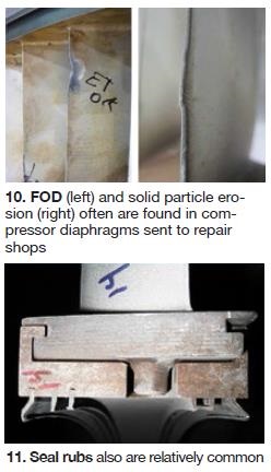 att Walton, PE, one of six presenters at the 501F and 501G on compressor diaphragm repairs, covered common wear mechanisms and failure modes, inspection, and repairs in a well-organized and well-illustrated presentation. Access 501F Compressor Solutions, a recorded webinar, presented by Walton and Fernando Romero for greater detail.
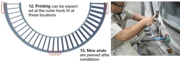
The primary failure modes, he said, were solid particle erosion and foreign object damage (FOD, Fig 10), seal rubs (Fig 11), fretting and contact stress, distortion, and high-cycle-fatigue (HCF) cracking. Fretting damage often is found at the outer hook fit and can be expected to extend 6 in. from the split lines and at the bottom quadrant (Fig 12).
Distortion of diaphragms may be caused by pressure loads in the early stages of the compressor, heat in the latter stages; and also by millwrights during disassembly. HCF, which is not common, can be caused by cyclic aerodynamic loading.
Inspection begins with an overall visual review of components, Walton continued. A fixture fit typically is next, followed by verification of critical dimensions (hook-fit thickness, twist, roundness, seal diameters, etc). Disassembly, cleaning, and NDE are next; a tap test is common.
Repairs are rated either minor or major. In the former group are the following tasks:
- Straighten, blend, and weld repair airfoils.
- Seal tooth straightening and deburring.
- NDE.
- Recoating.
- Reassembly.
- Fixture check and dimensional inspections
Major repairs typically are initiated by hook welding or other nonstandard requirements. They include all of the tasks identified above adjusted for the degree of damage, plus:
- Plating.
- Undercutting and welding of hookfits.
Seal replacement is possible, Walton said, noting that angled seals have to be specially made. Seals are removed by machine, new seals installed and peened (Fig 13).
Vogt Power International. Deron Johnston and Chelsey Beals were a change of pace for the 501F and 501G users attending Vendorama, most of the presentations being focused on gas turbines. Their message was clear: F-class combined cycles operating on 1800-psig/1050F main steam typically take 1.5 to 2.5 hours to go from cold iron to base load, but this doesn’t have to be. It is possible to decrease the start-up time, while also reducing life consumption.
One example they gave was for a 2 × 1 combined cycle powered by two 7F engines and having an HP drum operating pressure of about 1500 psig. Plant averaged two starts weekly so warm starts were a rarity. Average start time a couple of years ago was 3.5 hours; today it is 2 hours.
Critical to the dramatic reduction in start time was to minimize HP drum pressure/temperature loss between starts by closing steam vents and drains, stack damper, and IGVs quickly after shutdown. They stressed verifying leak-tightness of drains to avoid filling the drum with cold feedwater.
More solutions for reducing startup times with conventional heat-recovery steam generators can be found in How to design, retrofit drum-type HRSGs to cycle, start faster.
Camfil Power Systems. Many suppliers of gas-turbine air inlet filters participate in every user group meeting. At the 2014 conference of the 501F and 501G users there were at least half a dozen; five presented in Vendorama. In such a competitive environment, it’s easy for plant O&M personnel to become overwhelmed with information and lose focus of filter characteristics of greatest significance for the operating profile and ambient environment of their turbines.

Camfil’s solution was to build a mobile test laboratory to evaluate candidate filters in what would be their actual operating environment, thereby eliminating the need for endless discussions of features and benefits between plant personnel and alternative suppliers. Senior Product Engineer Jim Benson noted in his presentation that local contaminants are different than “standard” laboratory contaminants and onsite testing provides the most accurate information regarding filtration efficiency and pressure drop. Trend analysis is possible because testing typically is done over a period of about four months.
The Camlab case history presented by Benson was used to compare a new Camfil synthetic media for coastal environments to a widely used F7 blended media. The mobile laboratory was moved to a southern site (Fig 14) with challenging environmental conditions: salt-laden air and subtropical climate with hot, rainy summers and recurrent relative humidity levels approaching 100%. The results showed the synthetic media outperformed the alternative.
Precision Iceblast Corp. Matt Peterson talked to attendees about the many uses for CO2 blasting and other tasks that can be done when this equipment is onsite to clean HRSG tubes—including, cleaning of catalyst, compressor blades, generators, air inlet houses, inside and outside stacks, etc. He then reviewed the negative effects of HRSG fouling (higher GT backpressure), reasons for cleaning (improve thermal performance, prevent tube degradation), how to evaluate alternative service providers, etc.
Most attendees knew why it was necessary to clean the external surfaces of tubes in their heat-recovery steam generators, but not all were aware that some cleaning technologies are more effective than others. Peterson devoted several slides to Precision Iceblast’s deep-cleaning technology for extending maintenance intervals.

The company uses tube spreading equipment designed specifically for a given HRSG to open lanes between tube rows for more effective removal of deposits, which might include ammonia salts, sulfur compounds, corrosion products, and liberated insulation. He explained that tube spreading has never damaged tubes. Benefit of deep cleaning is illustrated by the photos. Fig 15 shows the condition of tubes as found, the photo in Fig 16 was taken after conventional cleaning, and that in Fig 17 after tube spreading and deep cleaning.
EthosEnergy Group. Chris Chandler, chief technologist, turbine optimization, explained the operational benefits automated tuning brings to DLN combustion systems regarding the simultaneous control of emissions, combustor dynamics, and turbine performance. The company’s ECOMAX™ solution, which predates Wood Group’s acquisition of Gas Turbine Efficiency, allows plant operators to fully customize operating objectives. With customized pre-set parameters, they can choose from among optimal NOx, dynamics, and power—with on/off toggle switches for easy and immediate switching from one to another.
System works this way: The CDM system continuously monitors dynamics and relays this information to ECOMAX, either directly or indirectly, through the plant DCS or similar controller. Using real-time combustion dynamics monitoring, continuous emissions monitoring, and turbine performance data, ECOMAX determines when tuning is necessary and automatically adjusts the turbine to suit the operator’s optimization goals. A user’s experience with the system was reported earlier by CCJ.
Chandler also discussed the power increase possible using the ECOMAX Tru-Curve™ process, which raises a turbine’s base-load fuel-to-air ratio to boost output and decrease heat rate, while simultaneously managing both emissions and combustor dynamics within acceptable levels. Tru-Curve can be limited to maintain a unit’s firing temperature at, or below, the OEM’s design limit.
The results of two case studies revealed that with Tru-Curve, the heat rate of a 2 × 1 F-class combined cycle improved by from 0.2 to 0.25%, output from 8 to 11 MW. The power boost for an F-class simple-cycle unit with Tru-Curve was 4 to 5 MW. These results were achieved with the firing temperature maintained within OEM recommendations.
Chandler also discussed limits to automated tuning that might apply during GT startup and the ability of ECOMAX to improve turndown by up to about 10%. Only a field test can verify the extent of turndown possible, he said.
The Chief Technologist’s concluding remarks noted the ECOMAX was installed on 42 units at the time of the 501F and 501G User Group meetings—all on units with DLN2.6 combustion systems and equipped with Mark V, VI, or VIe controls; 14 more systems were in various stages of implementation. Total operating hours were approaching 350,000. Of particular importance to attendees was that ECOMAX was in the final phase of testing on two 501F engines.
Donaldson Company Inc’s speaker spent most of his podium time “educating” users about filter testing and standards to help them make sound buying decisions. He had the following objectives for his talk and did well to achieve them all given the time constraints:
- Identify key factors to consider when beginning to evaluate filter options for a gas-turbine inlet system.
- Provide a general understanding of criteria used to establish filtration efficiency ratings based on the following standards: ASHRAE 52.2, EN779:2002 and EN779:2012, EN1822, ISO29461-1 (new).
- Prepare summary sheets of key points from each standard as a reference guide for owner/operators.
The presentation, available here, is akin to a CliffsNotes version of important filter nomenclature and standards. It will come in handy in the evaluation of alternative media.
C C Jensen Inc. The unflappable Axel Wegner spoke on the subject of lube-oil (and control oil) conditioning and practical analysis at yet another user-group meeting with still a different presentation covering the same material. Wegner always keeps his presentations “fresh” and no matter how many times you listen to him you’ll learn something new. However, there is one constant: When it comes to solving a varnish problem, the solution in virtually all cases is the VRU (varnish removal unit) described in the second half of his 2014 Vendorama presentation, complete with before/after test data for 501F installations.
One of the handouts at the presentation was C C Jensen’s “Clean Oil Guide,” a 36-page, 6 x 9 in. booklet of value for training O&M personnel. Much like Barry Link’s presentation (item above) is a CliffsNotes type of summary for inlet air filter standards, the Jensen clean-oil publication is a guide for lube- and control-oil condition management. It covers sources of contamination (particulates, water, degradation products, and acid contamination), how to take samples, oil-sample analysis, methods of cleaning oil, the basics of oil filtration, recommendations for buying and handling oil, etc. Well-written text is supported by good illustrations and tabular material. Contact Wegner for copies.
Pneumafil LLC. The theme of Tony Poovey’s presentation, simply put, was “no question HEPA filtration provides excellent performance, but at a significant price.” He provided information that compared the specific fractional efficiencies of non-HEPA options to a HEPA solution and then compared the prices. Poovey said that users wanting high-efficiency performance, who don’t have the budget for HEPA, can get good results using MERV 16 filters in a multi-stage static filter system.
The basic filtration system for many plants without special needs might be a MERV 8 prefilter with a MERV 14 fiberglass final filter, he noted. Assume a cost “X” if you change the prefilter four times over two years and the MERV 14 once. A HEPA train with MERV 8 prefilter (change four times over two years), followed by a MERV 11 panel pleat intermediate filter (change four times over two years) and an H12 HEPA (change every two years) would cost four times as much as the basic option. But excellent performance can be achieved with a system consisting of a MERV 11 panel pleat (change every two years) and a MERV 16 synthetic (change every other year) for only about 50% more than the base system. Email gtinfo@pneumafil.com with questions.
AGTServices Inc. Mike Bresney relates well to plant personnel. He knows they attended his presentation, “Stator Winding Surface Discharge,” for insights on how to keep their generators operating reliably; their goal was not an engineering education. Bresney understands “keep it simple.”
He covered end-winding surface discharge, a/k/a corona, and slot-section surface discharge, a/k/a bar vibration sparking, which is conducive to spark erosion. Bresney asked the attendees, “Why is there surface discharge?” He then answered the question: Two surfaces separated by an air (or hydrogen) gap have a voltage differential and when that voltage builds to a level the gap can’t sustain it discharges across the gap. “Kinda like a spark plug,” Bresney suggested.
Discharges may occur at relatively high frequency and generally are of low energy. But they can degrade winding semi-conductor material and binder, and damage insulation over time. Bresney showed a series of good photos illustrating his talking points and offered guidance on how to stop surface discharges. Think about why a spark plug fails, he said, and the corrective action becomes apparent: increase the gap and sustain the voltage, eliminate the gap and short it out, or foul the area and bleed off voltage. More photos illustrated these points.
Next he asked, and answered, why slot discharge occurs. Two surfaces (bars and core) are tied together electrically by semi-conductor armor; loose wedges allow for bar vibration; surfaces lose contact because of the vibration, allowing voltage to build and discharge across the gap. The solution: Maintain a tight wedge system. Demand side ripple springs, Bresney said.
The generator expert is a high-energy speaker and moved through his material quickly. Recognizing questions might arise after the session, Bresney suggested referring them to him at mike@agtservices.com or Jamie Clark at jclark@agtservices.com.
Advanced Turbine Support LLC. Mike Hoogsteden, Field Service Manager, had a two-part presentation. It began with a review of the capabilities of the latest commercial borescope equipment and what they mean to gas-turbine owner/operators, and concluded with a gallery of photos from 501F compressor, combustion, and turbine inspections to give users a better feel for issues experienced by some machines in the fleet.
Borescope technology has progressed dramatically in the last several years and instruments, like the GE XLG3 with stereo technology used by Advanced Turbine Support, are highly sophisticated and very expensive. Plus, trained and experienced technicians are required to extract maximum value from the technology. Hoogsteden said this equipment provides top accuracy for the following standard measurements:
- Length, without the need for the object to be perpendicular to the optical tip.
- Point to line—that is the distance between two points and a perpendicular line drawn to the line created by the two points.
- Depth. The difference in height between points on two different surface planes.
- Area. The size or surface area of a defect.
- Multi-segment length. This capability enables measuring the length of a non-linear defect or feature by integrating the lengths of shorter segments.
3D phase measurement capability (3D PM) also allows the borescope to scan a part and create a 3D surface map for making all measurements and providing different views of the subject of interest as required. Plus, 3D PM allows measurement of clearances between rotating and stationary blades. CCJ