


Anand Gopa Kumar, analysis manager, HRST Inc, coached the audience through a relatively new onsite crack-size assessment technique, conducted along with ALS Industrial Services, that has now been demonstrated “on a few HRSGs.” The technique, which follows API 579 and ASME-FFS-1 standards, combines transient thermal simulation (based on finite-element analysis) crack growth under drum operating conditions with standard NDE crack inspection methods—including magnetic-particle and ultrasonic testing.
The deliverable, if you will, is a failure assessment diagram (FAD) of the areas under investigation which reveals critical crack size (Fig 9) as a basis for decisions about remaining life, additional run time, etc. In other words, measure the crack dimensions (length and depth) and project their growth (assuming other variables are fixed) over the next operating cycle.
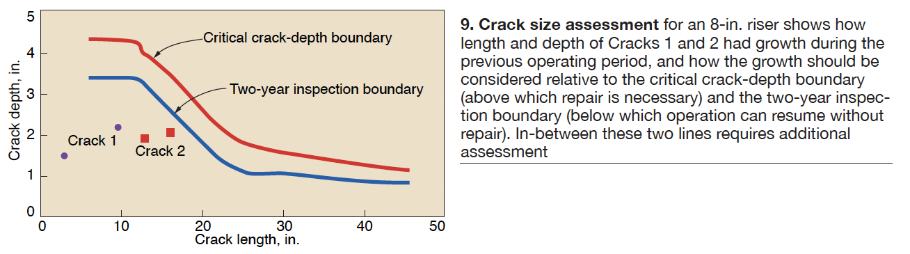
“All high-pressure drums should be periodically inspected but the thicker HP drums are most at risk,” Kumar said, with the area of greatest risk being the surfaces exposed to the 0-400-psig pressure range where the fastest temperature rises are experienced. “Thick cold drums plus fast pressure ramp equals stresses at the large nozzles,” Kumar noted. The shell-to-head area is also susceptible to cracking.
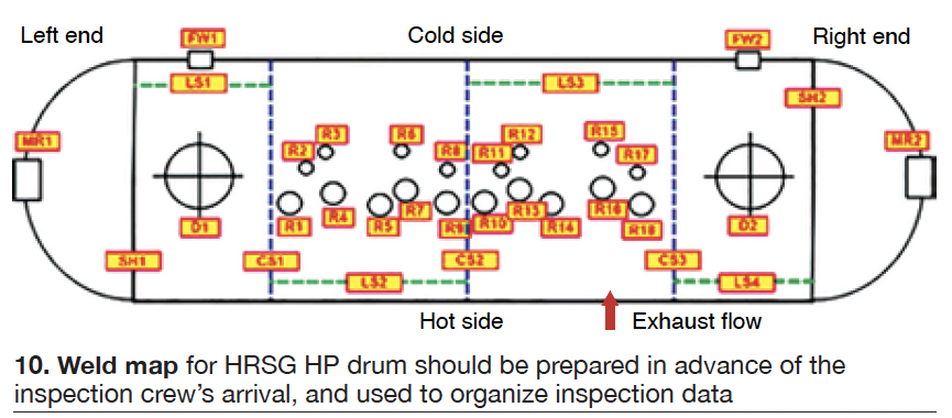
A typical F-class HRSG HP drum needs around eight different FADs, one for each of the major weld locations. The technique is best performed before an outage, so that relatively quick decisions can be made on repair during the outage versus continued monitoring.
The technique is applied to ID wall cracks, since removing insulation from the OD side usually is impractical or not possible. However, Kumar said, some cracks at OD weld areas can be detected from the inside. The analyst also has to consider adjacent cracks and the potential for crack interaction. “Sometimes cracks close together should be considered a single larger crack,” he said.
Many of Kumar’s slides were devoted to pre-outage, start of outage, and in-testing work. Pre-outage work includes organizing the information—such as design drawings, operating profile data, historical repair procedures, photos, and any other previous inspection results or
condition reports. Drum weld areas need to be properly exposed, cleaned, and prepped for NDT, and drum internals removed. Less obvious: Install snug-fitting foam plugs in nozzles to protect them from foreign objects and install lanyards on all tools if open holes exist.
At the start of the outage, inspect surface prep before the NDT crew arrives, label each weld location with paint stick per the drum weld location map (Fig 10), and protect nozzles from falling objects.
During testing, the technician performs mag-particle tests first, then the phased-array ultrasonic tests to accurately document the start of cracks, while being aware of multiple crack interactions. Length and depth of cracks must both be determined to decide whether more run time without repair is prudent. Decisions whether to leave as is or grind out shallow cracks must be made as well. Minimum wall thicknesses should also be calculated ahead of the outage, using ASME methods.
In response to questions, Kumar stated that fatigue-life calculations are not part of this exercise—these components typically do not operate in the creep temperature range—and it is uncommon to see cracks slow down or stop rather than continue to grow. Performing this technique before a unit enters cycling service can be especially valuable.